Towards Dual-band Reconfigurable Metamaterial Surfaces for Satellite Networking
Abstract.
The first low earth orbit satellite networks for internet service have recently been deployed and are growing in size, yet will face deployment challenges in many practical circumstances of interest. This paper explores how a dual-band, electronically tunable smart surface can enable dynamic beam alignment between the satellite and mobile users, make service possible in urban canyons, and improve service in rural areas. Our design is the first of its kind to target dual channels in the radio frequency band with a novel dual Huygens resonator design that leverages radio reciprocity to allow our surface to simultaneously steer and modulate energy in the satellite uplink and downlink directions, and in both reflective and transmissive modes of operation. Our surface, Wall-E, is designed and evaluated in an electromagnetic simulator and demonstrates 94% transmission efficiency and a 85% reflection efficiency, with at most 6 dB power loss at steering angles over a 150 degree field of view for both transmission and reflection. With surface, our link budget calculations predict 4 dB and 24 dB improvement in the SNR of a link entering the window of a rural home in comparison to the free-space path and brick wall penetration, respectively.
1. Introduction
| Starlink | OneWeb | TeleSat | |
|---|---|---|---|
| Downlink | 10.8–12.7 | 10.7–12.7 | 17.8–20.2 |
| Uplink | 14.0–14.5 | 12.8–14.5 | 27.5–30 |
Recently, there has been much interest in Low Earth Orbit (LEO) satellite data networking, with multiple companies’ networks in various deployment phases. These networks consist of constellations of hundreds of satellites that afford advantages in latency and coverage (10.1145/3286062.3286075, ): examples include SpaceX’s Starlink with a constellation of 4,425 satellites, and Telesat. Current systems are generally designed with a dish antenna that the user mounts outside the buildings requiring service, which communicates with the satellite in both the uplink and downlink directions. The dish antenna then communicates with the modem through a wire leading from the dish into the building to a modem, which then wirelessly communicates with the user, typically via Wi-Fi.
While such networks are already deployed and seeing limited use, we believe intelligent reconfigurable surfaces will expand their applicability and improve their performance in at least the following three scenarios:
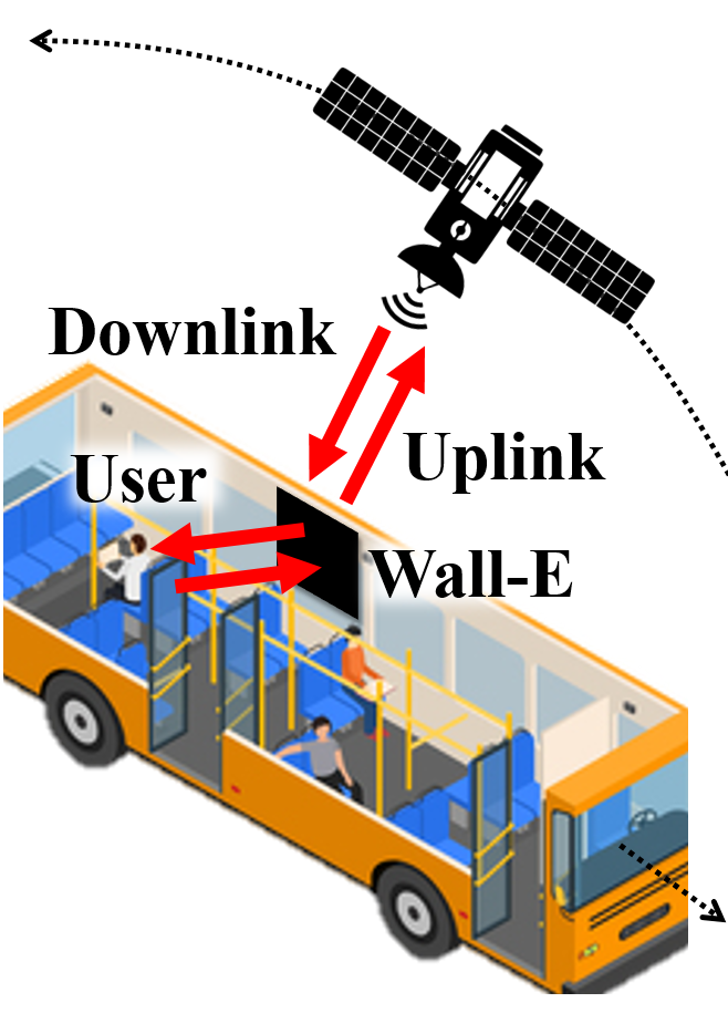
1. Rail/bus/airplane applications: For best performance, transportation systems (in particular high speed rail and airplanes) will demand adaptive systems to track the satellite currently serving the vehicle as well as handoff between satellites when the need arises. An electronically reconfigurable surface mounted on the windows and/or skylights of the vehicles can enable dynamic beam alignment to users inside.
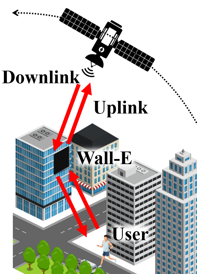
2. Service in urban canyons: Tall buildings in a city will reduce satellite lines of sight and preclude areas of coverage at or near street level for satellite networks. While 5G/NextG wireless coverage is maximized in cities, high frequency financial trading gains an advantage by using such networks (10.1145/3286062.3286075, ) and so urban deployment remains relevant. An electronically reconfigurable surface mounted externally mid-way up a skyscraper can enable service at street level via reflection off the building, while also allowing satellite signals to transmit into the building through the surface.
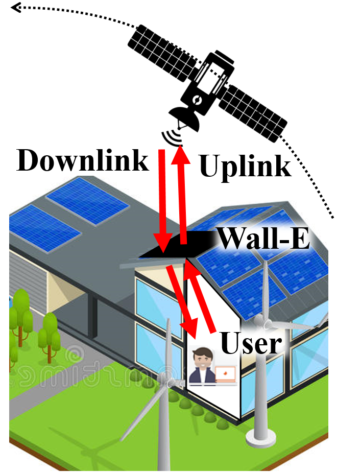
3. Rural service: While current LEO satellite systems require a dish and use a gateway to forward traffic between the satellite link and client, an electronically reconfigurable surface mounted on a window or skylight can refract the satellite link into the home directly, getting rid of the outside dish.
The band (10.7–18 GHz) is a natural choice for such low earth orbit satellite networks, as it has a longer wavelength (25–17 mm) than the higher frequency bands also in use (Table 1, mitigating the impact of precipitation somewhat, yet also has a wavelength short enough to create narrow beams for highly directional communication to ground. Since it has a short wavelength (25–17 mm) to experience loss when traversing heavy walls, it requires a line-of-sight (LoS) or near-LoS (i.e., traversing only through a low-loss material such as glass) path between the transmitter and receiver. A solution where instead of communicating with a dish relay through a gateway, a nearby surface refracts or reflects the satellite’s signal satellite to the user could reduce “outages” due to transient blockage, as it would allow path diversity, rerouting via the surface to avoid blockage. However, a key obstacle to realizing a smart surface design is that the frequency duplex division (FDD) communication in LEO satellite networks complicates operation, because such networks use different frequency sub-bands in the uplink (upper band) and downlink (lower band) directions, as Table 1 shows.
This paper explores innovations in the design space of LEO satellite networking with a Reconfigurable Intelligent Surface (RIS). In the process, we describe our early prototype surface design, Wall-E, a dual-band, metamaterial-based RIS design.
We first explore fundamental -band RIS design. In order to bring RIS-enhanced LEO networking to our scenarios, the surface should support both transmission (through the surface) and reflection (off the surface) modes. Huygens’ metasurfaces (HMSs) have shown to be promising in creating such transmissive and reflective functionalities in practice (cho2021mmwall, ; ding2020metasurface, ; liu2018huygens, ; chen2017reconfigurable, ; zhang2018space, ), thus achieving a full 360 degrees of control over radiated energy. While the basic principles of Huygens unit cells are known, designs that simultaneously make parsimonious use of electronic components (varactors and inductors), resonate at two or more different frequencies (bi-resonant), and achieve high efficiency are still open.
In LEO satellite networking, the process of aligning the physical wireless beam directions among user, surface, and satellite be very complex as both the satellite and user moves. Narrowing our design space to bi-resonant Huygens RIS designs, we next explore how to steer the uplink and downlink beams while preserving angular reciprocity, thus speeding the process of the beam alignment for the uplink via downlink transmissions, and vice-versa. This is of particular importance when both communication endpoints are moving rapidly, which is the case in a transportation scenario, satellite communicating with an airplane or train. In such cases, the LEO satellite network’s use of frequency duplexing division (FDD) allows for real-time, continuous feedback in both the uplink and downlink directions facilitating the constant tracking of the endpoints with respect to the RIS, and associated continuous updating of the RIS’ steering angles.
Finally, we consider starting directions for RISs to enable full end-to-end LEO network designs. We consider the handover process as the constellation of LEO satellites collectively moves over the earth, necessitating a handoff from one satellite to another, serving each user. The ability of the RIS to split uplink radio energy to two satellites and simultaneously combine downlink radio energy from two satellites makes a soft handover a possibility, which we explore further herein.
2. Huygens Metamaterials
By design, HMS-based surfaces consist of a layer of co-located orthogonal electric and magnetic meta-atom, facing each other across dielectric substrate, as shown in Fig. 2(a). The key principle is that the pair of two meta-atoms introduces a discontinuity in the impinging electromagnetic field whereby the meta-atoms manipulate field attributes, including magnitude and phase. In order to achieve on-demand control of the reflective/transmissive pattern, we mount a tunable, voltage-controlled electric component, known as varactor, on each meta-atom. Since varactors draw only a couple-of-hundred microwatts order of power, Wall-E consumes extremely low power. Unfortunately, HMS unit cells resonate at only one frequency (mono-resonanance) (PhysRevLett.110.197401, ) and thereby cannot act on the FDD links LEO satellite networks require.
Leveraging existing mono resonant structures for satellite networking, two alternative solutions are possible. Strawman (i)—building and deploying two single-band RISs (one for uplink and one for downlink). This approach would allow for FDD communication, but demands separate beam training for directional uplink and downlink, thereby doubling the overall delay of beam training. This is an important process because the satellite trajectory is not fully deterministic—it is subject to turbulence and uneven gravitational forces (najder2021quality, ; peng2018improving, )—and the terrestrial user is often mobile. Hence, the required three-party (LEO, RIS, user) beam training needs to be continuously performed for link maintenance. Strawman (ii)—Partitioning the surface into two subsets, each resonating at a different frequency. This approach has the advantage of link reciprocity, i.e., since the downlink and uplink resonant elements are co-located, the optimum surface configuration for a downlink transmission is very close (if not exactly the same) as that of the uplink transmission. However, with such partitioning, the number of surface elements is reduced by a factor of two (given a fixed form factor) in each band. Hence, the reduced directivity gain might not be sufficient to close the long-range air-to-ground links.
3. Design
We explore the key choices in our design space: we first discuss surface-enhanced LEO networking that leverages exiting mono-resonant structures and their shortcomings in realizing a directional, highly-mobile link. Then, we explain our unique dual-band meta-atom design and illustrate its key properties in fast link establishment and mobility management.
3.1. Building the Surface: Meta-Atoms
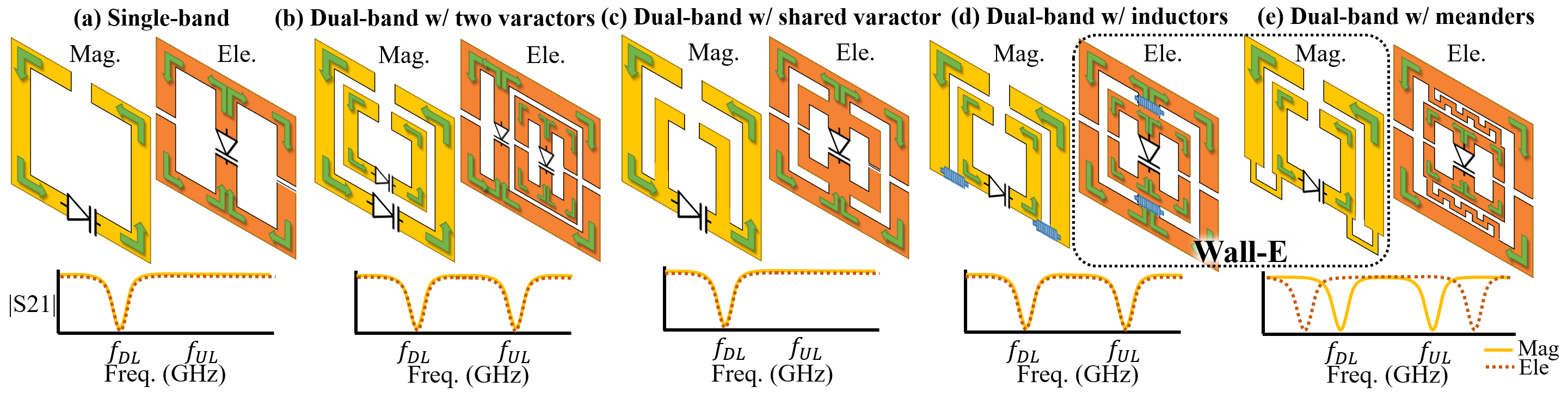
We now explore novel directions in the design space of the Huygens unit cell, composed of a magnetic side and an electric side, which we discuss in turn. Figure 2(a) illustrates a magnetic meta-atom structure that operates only in one frequency band. Here, the magnetic field of an incident electromagnetic wave induces a rotating current (denoted by green arrows) within the metallic loop (colored in yellow), which in turn produces its own magnetic field. To manipulate the field response, the meta-atom is integrated with a varactor diode, a voltage-dependent capacitor. The magnetic meta-atom is in essence a resonator consisting of both inductance and capacitance. Hence, the resonance response can be controlled via a varactor. Thus, a naïve approach to enabling bi-resonant unit cells would be to include two co-located metal rings (the inner ring optimized for the higher uplink frequency of 15 GHz, and the outer optimized for the lower downlink frequency of 10 GHz), as shown in Fig. 2(b). Although simple, this approach would require two separate varactors, increasing cost, insertion loss, and biasing complexity.
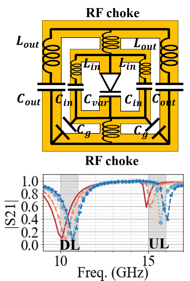
Instead, we want to control both outer and inner rings simultaneously, using a single shared varactor (Fig. 2(c)). However, we find that with such a structure, only the outer ring oscillates—thereby, the meta-atom effectively operates at only a single frequency. In order to allow the passage of low frequency signals into the inner ring, we load the connecting part with two RF chokes, which blocks the signal at higher frequency (for the inner ring) and passes the signal at lower frequency (for the outer ring). We can design the choke in two ways: mount coil inductors (Fig. 2(d)) or by bridging the outer and inner rings with a thin meander line copper trace (Fig. 2(e)). By adjusting meander width and length, we can apply a proper inductance value to choke off signals. Since coil inductors increase insertion loss, we finally choose Fig. 2(e) as our preferred magnetic side design candidate.
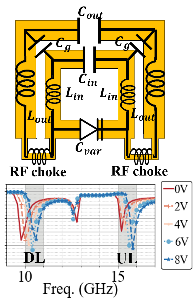
Figure 2(a) also shows the electric side, resonating in one frequency band only. The electric field of an incident wave induces a rotating current within the metallic loop (colored in orange), which in turn produces its own electric field. Similar to the magnetic meta-atom, Fig. 2(c) shows two electric meta-atoms with a shared varactor. To properly control two rings using one varactor, we again connect two rings with RF chokes. As shown in Fig. 2(d), the outer ring has oscillating currents at a lower frequency (downlink), and the inner ring has its own oscillating current at a higher frequency (uplink). However, unlike the magnetic meta-atom, we do not use meander traces as a RF choke for the electric meta-atom, because the meander trace would need to be placed in the gap between the two rings due to the different structure of the electric meta-atom. Increasing this gap, however, would create a huge frequency difference between two rings as shown in the transmission response of Fig. 2(e). Hence, we select the Fig. 2(d) as our preferred electric side candidate.
Equivalent Circuit. Fig. 3 illustrates the candidate design’s equivalent circuit diagram, with the corresponding magnitude of transmission coefficient , across different frequencies, and across different applied varactor control voltages. By definition, HMS currents oscillate at a resonant frequency where is the inductance and is the capacitance of the meta-atom. In Fig. 3, we see that each electric and magnetic meta-atom operates at two resonant frequencies, one at downlink and another at uplink. The resonant frequency for the downlink is largely affected by the outer ring’s inductance and capacitance while the inner ring’s inductance and capacitance mainly determines the uplink’s resonant frequency. By increasing the voltage to the varactor, we decrease the total capacitance of the meta-atom, which, in turn, shifts the resonant frequencies, meaning that on each side, we can control both the outer and inner rings with just a single varactor.
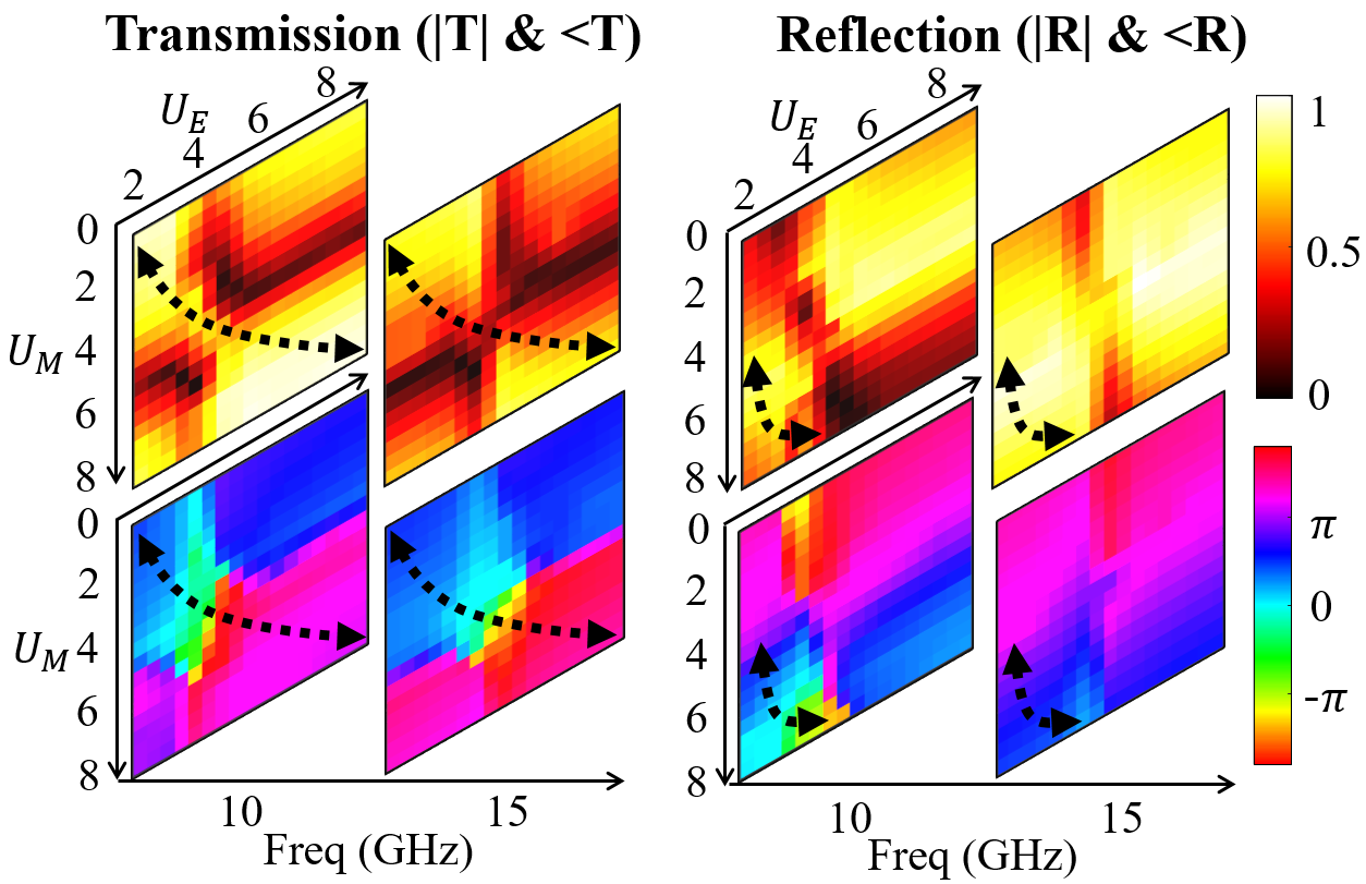
Huygen’s Pattern. When we place the electric and magnetic meta-atoms together as shown in Fig. 5 and sweep the voltage across two varactors and , we obtain the transmission and reflection coefficient pattern, so called Huygen’s pattern as depicted in Fig. 4. This pattern demonstrates a full transmission and reflection phase coverage of with near-lossless amplitude on the area marked by the black dotted curve. While a single-band HMS obtains the Huygen’s pattern at only one frequency, our design achieves this at both frequencies, enabling bi-directional control of an FDD signal. We will further optimize our inner rings for better uplink patterns.
3.2. Establishing a Surface-Satellite Link
Owing to the mobility of the LEO satellite as well as the end users, beam alignment plays a key role in maintaining the link quality of mobile satellite communication networks. We note that the coarse trajectory of the satellite is known a priori (and hence can be incorporated in beam adaptation protocols); yet, the exact real-time location of satellite cannot be perfectly predicted due to the numerous factors like turbulence and uneven gravitational forces (najder2021quality, ; peng2018improving, ). More importantly, the end point user is often mobile adding to the complexity of the three-party beam search between the satellite, user, and the surface. Conventional beam alignment protocols implement a trial-and-error scheme and test different potential directions sequentially. Extending such schemes to surface-enhanced satellite networks yield an increased delay as the beam training should be repeated at two different spectral bands. In fact, (guo2021two, ) demonstrates that a simulatenous uplink and downlink beamforming design in RIS-assisted FDD systems achieves more than times transmission rate over a one-way beamforming design (yu2019miso, ; liu2020intelligent, ; hua2021reconfigurable, ).
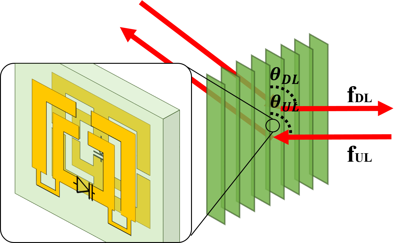
On the other hand, Wall-E can simultaneously steer the downlink and uplink beams at the same angle due to angular reciprocity. Specifically, assume a certain biasing voltage configuration applied to the surface such that creates a transmissive steering angle of for the incident downlink signal at 10 GHz, as shown in Fig. 5. Due to the angle reciprocity, an uplink signal impinging the surface at will be redirected toward the satellite location. Hence, angular reciprocity facilities fast beam alignments in FDD satellite networks as the surface configuration optimized for downlink transmissions works under the uplink communication and vice versa.
3.3. Enhancing Satellite-Satellite Handover
The fast movement of LEO satellites (around 7.5 km/s velocity relative to a reference point on the ground (cakaj2021parameters, )) can cause multiple handovers resulting in an increase of RTT and a significant throughput drop. Even though other access networks (such as cellular networks) also experience handover, the impact of handovers on the transport layer and quality of service is relatively small, because of their relatively shorter RTT and thereby faster link recovery. We argue that an RIS-enhanced satellite network can substantially alleviate this problem. In particular, Wall-E supports soft handovers by allowing two (or multiple) satellites impinge on the surface at the same time. By carefully choosing the voltage configuration at each meta-atom, Wall-E achieves beam combining and steering. In this case, as the primary satellite fades away due to mobility, the secondary satellite will ensure a non-interrupted link. We highlight that such flexible handovers is owed to the on-demand wavefrom engineering at Wall-E.
4. Feasibility
To project the feasibility of a RIS for LEO satellite networking, we simulate the performance of our design with HFSS EM simulation. We also model our varactor based on its Simulation Program with Integrated Circuit Emphasis (SPICE) model for an accurate capacitance value at our operating frequencies. In the future, we will fabricate and implement Wall-E and experiment with actual satellite signals.
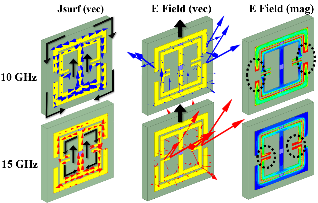
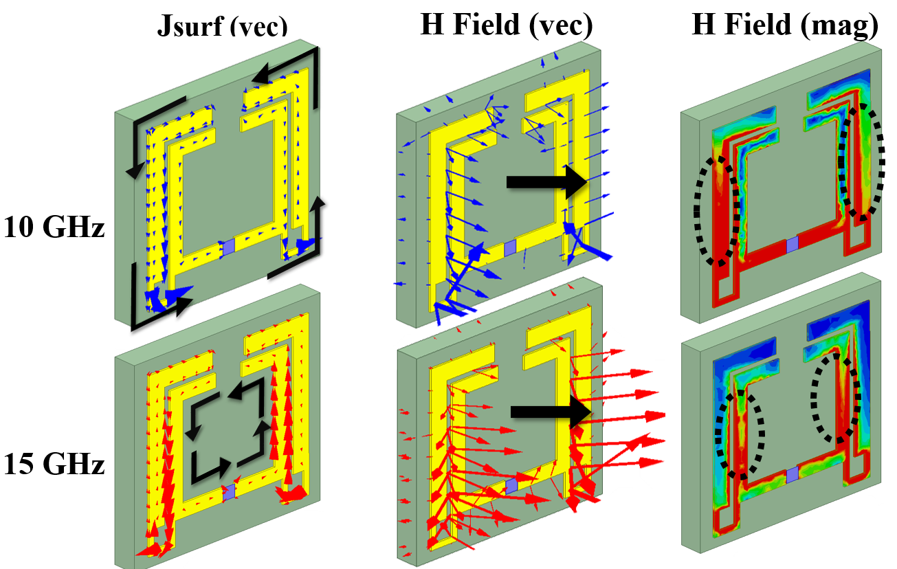
Near-Fields. Figure 6 illustrates the electric meta-atom’s surface currents and electric fields (Fig. 6(a)) along with the magnetic meta-atom’s surface currents and magnetic fields (Fig. 6(b)) at GHz and GHz. For both electric and magnetic meta-atom, the surface currents oscillate on the outer ring at GHz while they oscillate on the inner ring at GHz. We denote the direction of in black arrows, which conforms to Fig. 2. Similarly, the fields are excited by the outer ring in GHz by the inner ring in GHz. Fig. 6 confirms the bi-resonate nature of the Wall-E meta-atoms.
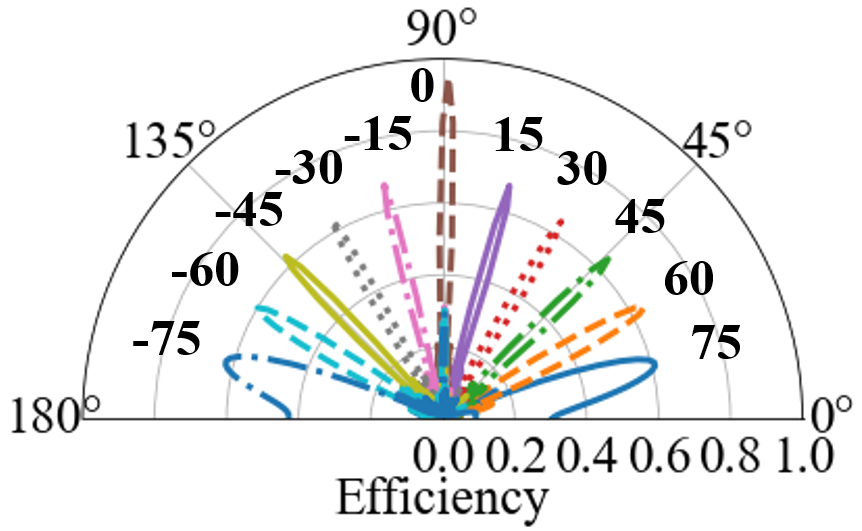
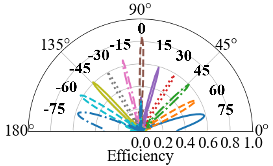
Radiation Efficiency. In this section, we demonstrate a high efficiency of Wall-E, which determines the end-throughput. Specifically, we calculate the efficiency as a magnitude of an array factor at a desired angle:
| (1) |
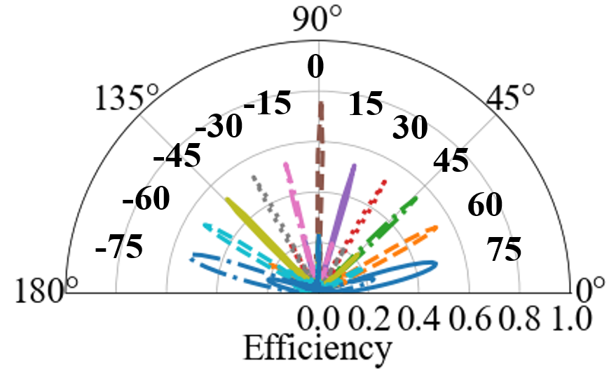
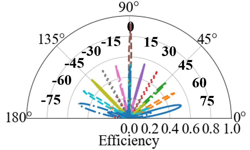
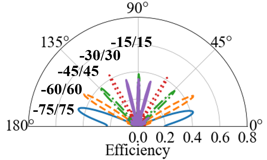
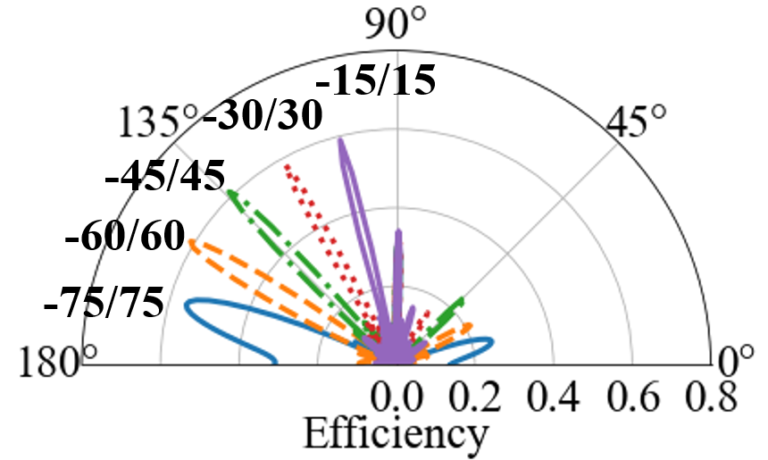
where , is a meta-atom spacing, is a steering angle, and is a complex value chosen from Fig. 4. Fig. 7 shows the efficiency of Wall-E as it steers the beam with the step of -degree. Specifically, Fig. 7(a) demonstrates the efficiency of downlink transmission, which ranges from % to %. Similarly, Fig. 7(b) illustrates the downlink efficiency as Wall-E reflects the beam, which ranges from % to %. Fig. 7(c) and Fig. 7(d) reveal the efficiency of % to % for uplink transmission and reflection. Moreover, we highlight Wall-E’s beam-split performance in Fig. 8 for a soft-handover. Here, we split the beam , , , , and degrees apart. Specifically, the power is evenly divided for each beam on Fig. 8(a), and it is unevenly splitted for Fig. 8(b) ( on left and on right). The result demonstrates that Wall-E can tailor the beams in a flexible manner, which enables a highly-efficient relay and hand-over in FDD communication.
Link Budget. In this section, we analyze our back of the envelope calculation for closing a 1,150-km air-to-ground link. We formulate a link budget in decibel as follow:
| (2) |
where is a transmit power, including the transmitter gain. The Maximum Transmit EIRP of a most powerful satellite is dBW, which is equivalent to dBm (albulet2016spacex, ). We assume that the transmit power is dBm for downlink. is a free-space path loss between the satellite and Wall-E. Since an orbital height from Earth is approximately 1,150 kilometers (albulet2016spacex, ), the free-space path loss is dB for downlink and dB for uplink. is a dB loss of window where the Wall-E is placed. Assuming -meter distance between Wall-E and user, is dB. is the receiving gain, which is equivalent to the gain of the user in downlink. We assume that the gain of the user is dB. Lastly, and is Wall-E’s receiving and transmitting gain, respectively. Each is calculated based on the effective aperture, . Specifically, the surface gain where is the radiation efficiency of Wall-E at a steered angle . Finally, we obtain the SNR in decibel by subtracting the noise power from the signal power.
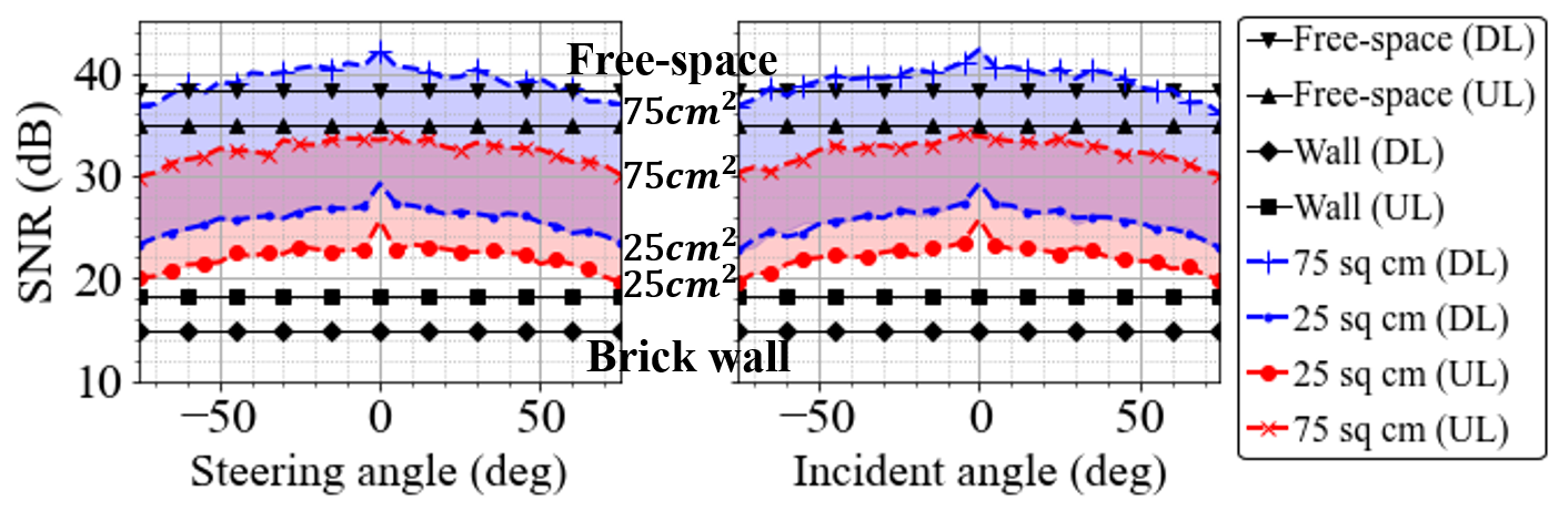
Figure 9 demonstrates the simulated SNR as Wall-E steers the beam in two scenarios. The first scenario has the incident beam perpendicular to the surface, and the surface steers from to degrees. On the other hand, the second scenario varies the angle of the incident beam from to degrees while Wall-E steers the beam in a perpendicular direction. For each scenario, we vary the size of Wall-E and compare the simulated results against the free-space path and brick wall blockage in the absence of Wall-E. For both scenarios, the larger the surface is, the higher the SNR is. In particular, the SNR of sized Wall-E is higher than the SNR of the free-space path for over a degree field of view. Compared to the brick wall blockage scenario, sized Wall-E provides approximately dB higher SNR.
5. Related Works and Discussion
Dual-Band Metasurfaces. Dual-band metasurfaces have recently gained attention for various applications however the existing architecture fall short in meeting at least one of our requirements, namely, on-demand and flexible reconfiguration, transmissive and reflective modes, and 360-degree coverage. In particualr, Han et al. (han2021dual, ) introduced a dual-band transmission metasurface for S- and C-bands, which provides wide-band operation with high transmission efficiency. However, the surface lacks dynamic configuration which makes it inapplicable in our highly mobile air-to-ground application. Saifullah et al. (saifullah2021dual, ) proposed a dual-band programmable reflective metasurface that operates in C- and Ku- bands using PIN diodes. However, this design supports only the reflection mode; thereby, it’s not suitable for through-wall applications. Further, the use of PIN diodes limits the phase shifting resolution and hence the beam steering efficiency. On the contrary, Rotshild et al. (rotshild2021ultra, ) employs varactors to achieve a continuous phase control. Unfortunately, this design is also reflection-only and is limited in angular coverage. To the best of our knowledge, Wall-E is the first design prototype of a dual-frequency reflective/transmissive reconfigurable metasurface with a phase coverage and high radiation efficiency.
Reflectarray Satellite Antennas. Prior works (encinar2006dual, ; encinar2011transmit, ; prado2015design, ; imaz2020reflectarray, ) have proposed the use of reflectarray antennas for space communication, where the reflectarray is placed on the satellite and is excited via the feed horn. Such an architecture can realize flexible steering as the reflected signal can be dynamically steered according to the array configuration. Furthermore, (patyuchenko2014digital, ; martinez2020multibeam, ) explored the multibeam reflectarrays for the multispot coverage from the satellite. Metasurfaces and reflectarrays are both spatially-fed structure composed of small elements. However, in contrast to existing efforts, we propose using a metasurface as an intermediate node (hence not co-located with the satellite nor end user) to increase path diversity. In doing so, Wall-E’s capability to support both transmission and reflection plays a key role.
Wall-E for Satellite Link Aggregation. While gaining a lot of attention, the bandwidth of a single satellite path is unlikely to provide low-latency links comparable with a fiber path (10.1145/3286062.3286075, ). However, aggregating abundant paths from many satellites within coverage zone of a user can, in principle, offer lower latency than a fiber path. We highlight that Wall-E can play a crucial role in realizing satellite link aggregation by combining and steering the incident signals from multiple satellites into a desired direction. In the future, we will investigate novel scheduling algorithms for optimum coordination between multiple parties (all nearby LEOs, RIS, and user) and extend the prior efforts (vasisht2021l2d2, ; vazquez2018precoding, ; fan2021efficient, ) on link satellite scheduling that do not address multi-satellite and RIS-enhanced networking.
References
- [1] M. Albulet. Spacex non-geostationary satellite system. FCC Application SATLOA2016111500118, 2016.
- [2] S. Cakaj. The parameters comparison of the “starlink” leo satellites constellation for different orbital shells. Frontiers in Communications and Networks, 2:643095, 2021.
- [3] K. Chen, Y. Feng, F. Monticone, J. Zhao, B. Zhu, T. Jiang, L. Zhang, Y. Kim, X. Ding, S. Zhang, et al. A reconfigurable active huygens’ metalens. Advanced materials, 29(17):1606422, 2017.
- [4] K. W. Cho, M. H. Mazaheri, J. Gummeson, O. Abari, and K. Jamieson. mmwall: A reconfigurable metamaterial surface for mmwave networks. In Proceedings of the 22nd International Workshop on Mobile Computing Systems and Applications, pages 119–125, 2021.
- [5] I. Del Portillo, B. G. Cameron, and E. F. Crawley. A technical comparison of three low earth orbit satellite constellation systems to provide global broadband. Acta astronautica, 159:123–135, 2019.
- [6] X. Ding, Z. Wang, G. Hu, J. Liu, K. Zhang, H. Li, B. Ratni, S. N. Burokur, Q. Wu, J. Tan, et al. Metasurface holographic image projection based on mathematical properties of fourier transform. PhotoniX, 1(1):1–12, 2020.
- [7] J. A. Encinar, M. Arrebola, F. Luis, and G. Toso. A transmit-receive reflectarray antenna for direct broadcast satellite applications. IEEE Transactions on Antennas and Propagation, 59(9):3255–3264, 2011.
- [8] J. A. Encinar, L. S. Datashvili, J. A. Zornoza, M. Arrebola, M. Sierra-Castañer, J. L. Besada-Sanmartin, H. Baier, and H. Legay. Dual-polarization dual-coverage reflectarray for space applications. IEEE Transactions on Antennas and Propagation, 54(10):2827–2837, 2006.
- [9] H. Fan, Z. Yang, S. Wu, X. Zhang, J. Long, and L. Liu. An efficient satellite resource cooperative scheduling method on spatial information networks. Mathematics, 9(24):3293, 2021.
- [10] B. Guo, C. Sun, and M. Tao. Two-way passive beamforming design for ris-aided fdd communication systems. In 2021 IEEE Wireless Communications and Networking Conference (WCNC), pages 1–6. IEEE, 2021.
- [11] J. Han and R. Chen. Dual-band metasurface for broadband asymmetric transmission with high efficiency. Journal of Applied Physics, 130(3):034503, 2021.
- [12] M. Handley. Delay is not an option: Low latency routing in space. In Proceedings of the 17th ACM Workshop on Hot Topics in Networks, HotNets ’18, page 85–91, New York, NY, USA, 2018. Association for Computing Machinery.
- [13] S. Hua, Y. Zhou, K. Yang, Y. Shi, and K. Wang. Reconfigurable intelligent surface for green edge inference. IEEE Transactions on Green Communications and Networking, 5(2):964–979, 2021.
- [14] B. Imaz-Lueje, D. R. Prado, M. Arrebola, and M. R. Pino. Reflectarray antennas: A smart solution for new generation satellite mega-constellations in space communications. Scientific Reports, 10(1):1–13, 2020.
- [15] M. Liu, D. A. Powell, Y. Zarate, and I. V. Shadrivov. Huygens’ metadevices for parametric waves. Physical Review X, 8(3):031077, 2018.
- [16] Y. Liu, J. Zhao, M. Li, and Q. Wu. Intelligent reflecting surface aided miso uplink communication network: Feasibility and power minimization for perfect and imperfect csi. IEEE Transactions on Communications, 69(3):1975–1989, 2020.
- [17] D. Martinez-de Rioja, E. Martinez-de Rioja, Y. Rodriguez-Vaqueiro, J. A. Encinar, and A. Pino. Multibeam reflectarrays in ka-band for efficient antenna farms onboard broadband communication satellites. Sensors, 21(1):207, 2020.
- [18] J. Najder and K. Sośnica. Quality of orbit predictions for satellites tracked by slr stations. Remote Sensing, 13(7):1377, 2021.
- [19] A. Patyuchenko, C. Tienda, M. Younis, S. Bertl, P. Lopez-Dekker, and G. Krieger. Digital beamforming sar interferometer based on a multi-beam reflectarray antenna. In EUSAR 2014; 10th European Conference on Synthetic Aperture Radar, pages 1–4. VDE, 2014.
- [20] H. Peng and X. Bai. Improving orbit prediction accuracy through supervised machine learning. Advances in Space Research, 61(10):2628–2646, 2018.
- [21] C. Pfeiffer and A. Grbic. Metamaterial Huygens’ surfaces: Tailoring wave fronts with reflectionless sheets. Phys. Rev. Lett., 110:197401, May 2013.
- [22] D. R. Prado, A. Campa, M. Arrebola, M. R. Pino, J. A. Encinar, and F. Las-Heras. Design, manufacture, and measurement of a low-cost reflectarray for global earth coverage. IEEE antennas and wireless propagation Letters, 15:1418–1421, 2015.
- [23] D. Rotshild and A. Abramovich. Ultra-wideband reconfigurable x-band and ku-band metasurface beam-steerable reflector for satellite communications. Electronics, 10(17):2165, 2021.
- [24] Y. Saifullah, Q. Chen, G.-M. Yang, A. B. Waqas, and F. Xu. Dual-band multi-bit programmable reflective metasurface unit cell: design and experiment. Optics Express, 29(2):2658–2668, 2021.
- [25] D. Vasisht, J. Shenoy, and R. Chandra. L2d2: Low latency distributed downlink for leo satellites. In Proceedings of the 2021 ACM SIGCOMM 2021 Conference, pages 151–164, 2021.
- [26] M. Á. Vázquez, M. B. Shankar, C. I. Kourogiorgas, P.-D. Arapoglou, V. Icolari, S. Chatzinotas, A. D. Panagopoulos, and A. I. Pérez-Neira. Precoding, scheduling, and link adaptation in mobile interactive multibeam satellite systems. IEEE Journal on Selected Areas in Communications, 36(5):971–980, 2018.
- [27] X. Yu, D. Xu, and R. Schober. Miso wireless communication systems via intelligent reflecting surfaces. In 2019 IEEE/CIC International Conference on Communications in China (ICCC), pages 735–740. IEEE, 2019.
- [28] L. Zhang, X. Q. Chen, S. Liu, Q. Zhang, J. Zhao, J. Y. Dai, G. D. Bai, X. Wan, Q. Cheng, G. Castaldi, et al. Space-time-coding digital metasurfaces. Nature communications, 9(1):1–11, 2018.