figure \cftpagenumbersofftable
The 511-CAM Mission: A Pointed 511 keV Gamma-Ray Telescope with a Focal Plane Detector Made of Stacked Transition Edge Sensor Microcalorimeter Arrays
Abstract
The 511 keV -ray emission from the galactic center region may fully or partially originate from the annihilation of positrons from dark matter particles with electrons from the interstellar medium. Alternatively, the positrons could be created by astrophysical sources, involving exclusively standard model physics. We describe here a new concept for a 511 keV mission called 511-CAM (511 keV gamma-ray CAmera using Micro-calorimeters) that combines focusing -ray optics with a stack of Transition Edge Sensor (TES) microcalorimeter arrays in the focal plane. The 511-CAM detector assembly has a projected 511 keV energy resolution of 390 eV Full Width Half Maximum (FWHM) or better, and improves by a factor of at least 11 on the performance of state-of-the-art Ge-based Compton telescopes. Combining this unprecedented energy resolution with sub-arcmin angular resolutions afforded by Laue lens or channeling optics could make substantial contributions toward identifying the origin of the 511 keV emission through discovering and characterizing point sources and measuring line-of-sight velocities of the emitting plasmas.
keywords:
gamma-ray telescopes, gamma-ray instrumentation†Farzane Shirazi, \linkablefshiraz@clemson.edu ‡Henric Krawczynski, \linkablekrawcz@wustl.edu
1 Introduction
The center of our Milky Way galaxy exhibits a strong 511 keV -ray signal from a yet-to-be-identified origin [1, 2, 3, 4, 5, 6, 7, 8]. The emission may be produced by the annihilation of positrons from dark matter decays with electrons from the interstellar medium [9]. Alternatively, the electrons and positrons might be created in X-ray binaries or other astrophysical sources, involving exclusively standard model physics [10]. The origin of the emission can be identified by mapping its spatial distribution, possibly discovering point sources, and by measuring the line-of-sight velocity dispersion of the electron-positron centers of mass immediately preceding the annihilation interactions [10]. Two experimental approaches can be used for this purpose: Compton telescope observations with a large field of view [7, 8], and pointed experiment observations with a narrow field of view [11, 12, 13, 14]. While the first approach excels at mapping the large-scale distribution of the 511 keV emission, the latter achieves far superior angular and energy resolutions. The importance of understanding the 511 keV emission makes a case for implementing both approaches.
In this paper, we describe the new 511-CAM mission concept that combines imaging or concentrating -ray optics with novel focal plane instrumentation. Even though pointed -ray missions have been proposed in the past [11, 12, 13, 14], our concept leverages, for the first time, the energy resolutions of microcalorimeters such as the SLEDGEHAMMER (Spectrometer to Leverage Extensive Development of Gamma-ray TESs for Huge Arrays using Microwave Multiplexed Enabled Readout) array developed by the NIST quantum sensor group. The SLEDGEHAMMER detectors achieve an unprecedented energy resolution of eV FWHM at 97 keV [15, 16, 17]. The 511-CAM based on the SLEDGEHAMMER technology is expected to give a 511 keV energy resolution of 330 eV FWHM, thus achieving a factor of 11 improvement in energy resolution compared to the current state-of-the-art HPGe (High Purity Ge) based Compton telescopes [7]. The dramatic improvement comes from the superior energy resolution for each individual energy deposit provided by the calorimetric approach, as well as the smaller number of interactions in high- absorbers used. The 511-CAM focal plane instrumentation can be combined with Laue lens imaging optics or channeling concentrator optics with focal lengths of 12 m or more to focus -rays onto the 511-CAM detector assembly (see Section 3). The 511-CAM concept would be well-suited for a (Ultra) Long Duration Balloon ((U)LDB) balloon flight or a satellite borne mission.
The rest of the paper is organized as follows. Section 2 highlights the scientific motivation for 511-CAM-type missions. Sections 3, 4, and 5 describe the optical, focal plane, and telescope design of a balloon-borne 511-CAM mission, respectively. We report on simulations of the performance of the focal plane detector in Section 6, and Section 7 presents the sensitivity achievable with the balloon borne mission. Finally, we summarize and discuss the results in Section 8.
2 Scientific Motivation
2.1 Identifying the Origin of the 511 keV Emission from the Galactic Center
The OSSE, INTEGRAL, and COSI (Compton Spectrometer and Imager) missions mapped the bright 511 keV emission from the galactic center region [1, 2, 3, 4, 5, 6, 7, 8]. For reference, the COSI mission measured the 511 keV line with a 4.3 keV FWHM energy resolution.
The review article by Prantzos et al. summarizes a number of potential dark matter and astrophysical explanations for the emission [10]. The dark matter explanations for the emission are placed into two categories: the decay and annihilation of MeV particles, or the de-excitation of dark matter in models with hidden sectors. Prantzos et al. note that different models predict distinct spatial distributions for the resultant positrons. Siegert et al. published upper limits and possible detections on the 511 keV fluxes from 39 dwarf satellite galaxies. The values found are well above the expectations from interpreting the Milky Way emission as purely a dark matter signal [18, 19]. Moreover, the MeV-scale dark matter annihilation interpretation of the 511-keV excess was challenged by measurements of the damping tail of the cosmic microwave background [20], but refined measurements [21], as well as modified dark matter annihilation mechanisms [22], still allow for this possibility. Cai et al. discuss the compatibility of mixed dark matter and primordial black hole explanations of the 511 keV emission and the INTEGRAL results, and highlight the importance of more sensitive follow-up observations [23]. The possibility of Hawking evaporation of a population of primordial black holes concentrated in the inner galaxy has also been considered, with a testable prediction of diffuse gamma ray emission from the inner galactic halo [24]. A 511-CAM-type mission with excellent spatial and energy resolutions can distinguish between discrete astrophysical sources and a potential dark matter origin of the 511 keV excess. In addition, the observations can provide important constraints on different dark matter models, as well as model-independent constraints on the dark matter density profile in the inner galactic region. The most significant contributions of such a mission would thus be to observe the brightest 511 keV -ray regions to search for bright central core emission and point sources. In the case of a positive detection, the data would constrain the line-of-sight velocity distribution of the emitting plasma.
2.2 Additional Scientific Goals of Pointed Gamma-Ray Observatories
The unprecedented energy resolution of a 511-CAM-based -ray mission can be used to scrutinize various source classes for electron-positron annihilation emission. A 511-CAM would thus enable a search for 511 keV emission from pair plasmas in X-ray binaries such as Cyg X-1 [25, 26]. The analysis of the NUSTAR observations of accreting stellar mass black holes indicates that the coronal temperatures frequently run against the upper limit at which pair cooling becomes significant, indicating that pair plasma may indeed be present. A 511-CAM-type mission would be particularly well-suited to finding pair plasma if the plasma is sufficiently far away from the black hole, such that the gravitational and Doppler broadening of the line is smaller than the 511-CAM’s energy resolution.
Additionally, electron-positron pairs may also be abundantly present in the collimated plasma outflows (jets) from stellar mass and supermassive black holes [27, 28]. The INTEGRAL-SPI instrument indeed revealed evidence for a 511 keV emission line in an outburst of the microquasar V404 Cygni [29]. The detection of a 511 keV emission (possibly Doppler-shifted, owing to the relativistic motion of the plasma) would give us a unique probe of the makeup and flow velocity of the jets. High–sensitivity, excellent energy resolution observations with a 511-CAM would thus be highly desirable.
A 511-CAM could furthermore observe X-ray lines from nucleosynthesis in various astrophysical settings. Harrison et al. describe prominent lines at 158, 749, and 812 keV (from the decay of 56Ni) and at 847 and 511 keV (from the decay of 56Co) in the spectra of SNe Ia. These two decays power much or all of the emission from SNe Ia [30], and a NUSTAR follow-up mission could detect several tens of these objects per year. A deeper understanding of SNe Ia explosion mechanisms would greatly benefit many areas of study, given their use as standard candles in astronomy and cosmology.
Finally, such an instrument could have even more relevant objects of study: Diehl et al. list prominent -ray lines at 68 keV and 78 keV (from the radioactive decay of 44Ti in core-collapse supernovae), at 122 keV and 158 keV (from decays of 57Ni and 56Ni, respectively, in supernova nucleosynthesis), at 478 keV (from the decay of 7Be in nova nucleosynthesis), and at 812 keV and 847 keV (from the decays of 56Ni and 56Co, respectively, in supernova nucleosynthesis) as important diagnostics for their respective source classes [31]. Similarly, the remnant of a neutron star merger that occurred between a thousand and a million years ago would emit prominent -ray lines with energies of 400 keV and 700 keV (from the decays of 125Sb, 126Sb, 140La, 213Bi, 214Bi, and 246Am), along with other lines at lower and higher energies [32]. However, experiments of reasonable size can detect only nearby galactic remnants.
3 Options for the 511-CAM -Ray Optics
3.1 Laue Lenses
A 511-CAM detector could be used in the focal plane of a pointed imaging or non-imaging (concentrating) -ray telescope. Two concepts for focusing -rays onto a detector have been explored in this study: Laue lens optics and channeling optics. Both methods can be used to collect photons over an area substantially larger than the detector area.
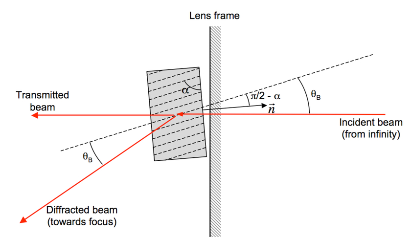
Laue lenses use rings of crystals to Bragg diffract the -rays from cosmic sources onto the detector, as shown in Fig. 1 [33, 12, 13, 14]. The focal length is given by , where is the radius of a given ring of crystals, and is the Bragg angle of the crystals [34, 13]. The wavelength bandpass of a single crystal resembles a delta function centered on the wavelength where the Bragg condition is met. Broader bandpass lenses can be constructed by (i) using different rings of crystals with different crystal orientations, (ii) employing crystals with a mosaic structure and thus with an angular spread of the diffracting planes, or (iii) implementing curved diffracting planes.
The CLAIRE mission used a 45 cm diameter, 2.77 m focal length Laue lens made of 556 Ge-Si crystals to achieve an angular resolution of 18 arcmin at 170 keV [33]. Small amounts of Si were added to the Ge during the crystal growth process to make mosaic crystals with a bandpass of 3 keV centered on 170 keV. The experiment was flown on a stratospheric balloon flight in 2001 and successfully detected -rays from the Crab Pulsar and Nebula [34]. The team is evaluating the merits of lenses made of Ge, Cu, SiGe, and commercially-produced mosaic gold crystals in order to reach higher energies. The test samples achieve the theoretical maximum efficiency of 31% at 600 keV [12, 14]. The focal length of a Laue lens scales with the -ray energy. CLAIRE’s 2.77 m focal length at 170 keV thus corresponds to a 511 keV focal length of 8.3 m. This focal length is approximately the same as that of the balloon-borne X-Calibur experiment (focal length: 8 m, flight in 2018/2019) [35], and only 67% of that of the upcoming XL-Calibur experiment (focal length: 12 m, flights in 2022/2024) [36]. Operating Laue lenses on balloon-borne payloads is thus demonstrably possible.
Smither reviews the Laue lens developments over the last few decades and presents experimental and theoretical results for lenses with focal lengths from a few meters to a few hundred meters [13]. A recent breakthrough in lens fabrication was achieved by making a lens from larger bent crystals rather than from hundreds of small crystals that need to be individually mounted and aligned. High detection efficiencies over a broad energy band can be achieved by separating the lens and detector by as much as 200 m. The Toulouse collaboration envisions a 2.2 m diameter lens with a 200 m focal length. The concept uses bent and unbent crystals and is projected to achieve a detection area of 600 cm2 in the two bands from 460 keV to 522 keV and from 825 keV to 910 keV [37, 13].
The focal spots of the 2.77 m focal length CLAIRE mission and the 200 m focal length mission with an angular resolution of 15 arcseconds both have a diameter of 1.5 cm. A 511-CAM detector array with a sensitive area of 3 cm diameter and mm diameter pixels would thus be a good match for either optical setup. A 12 m focal length lens with a 1 arcmin angular resolution would produce a 3.5 mm diameter focal spot, which would be nicely oversampled by mm diameter pixels.
3.2 Channeling Optics
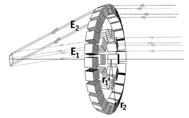
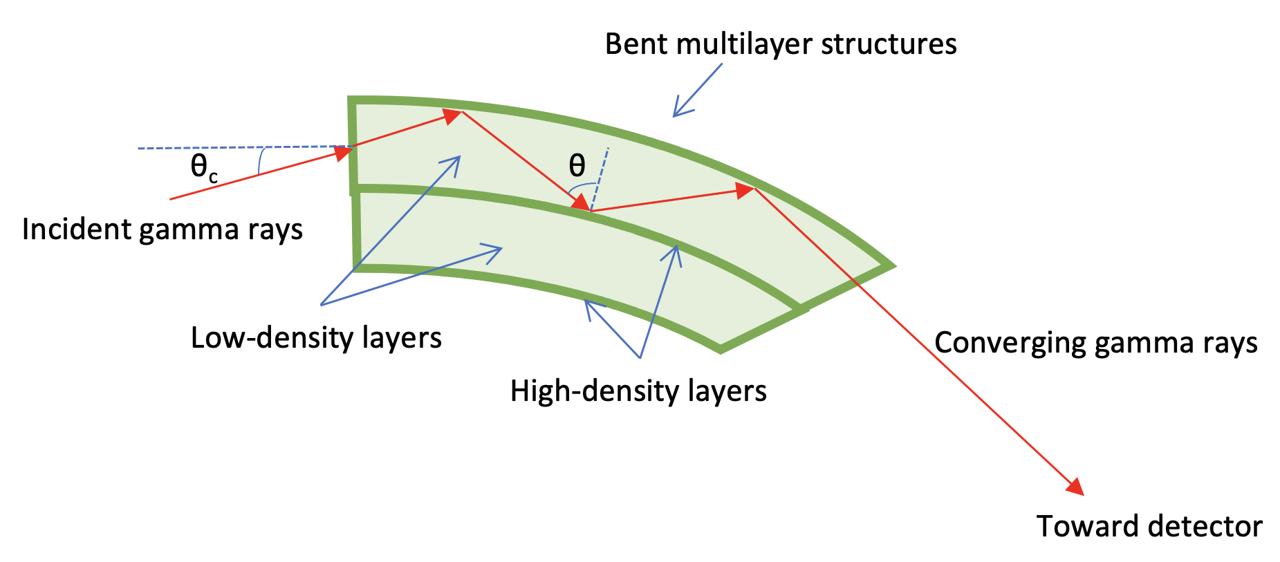
As an alternative to Laue lenses, channeling optics, first proposed by Kumakhov et al.[40], have recently received renewed attention [41, 42, 43, 44, 45, 46, 47, 48, 49]. Channeling optics use total external reflection off of gently curved multilayer structures, consisting of alternating layers of a high-density reflecting material and a low-density spacer material (Fig. 2). This technique would allow -rays to be concentrated to a small, shielded detector in the focal plane [50]. Since the photons can reflect multiple times within the structure, much larger bending angles can be achieved than for mirrors or Laue diffraction optics, resulting in much shorter focal lengths needed. Shirazi et al. [51] examined the 20 cm diameter lens constructed with Ir/Si that produced a 1 cm diameter focal spot over a 10 m focal length and a 50-430 keV energy range. The channeling process is effective over a broad energy band, as long as the angle of incidence is less than a certain critical angle and the photons are not excessively absorbed [49]. Smaller reflection angles and thus larger focal lengths can be used to extend the energy range to 511 keV.
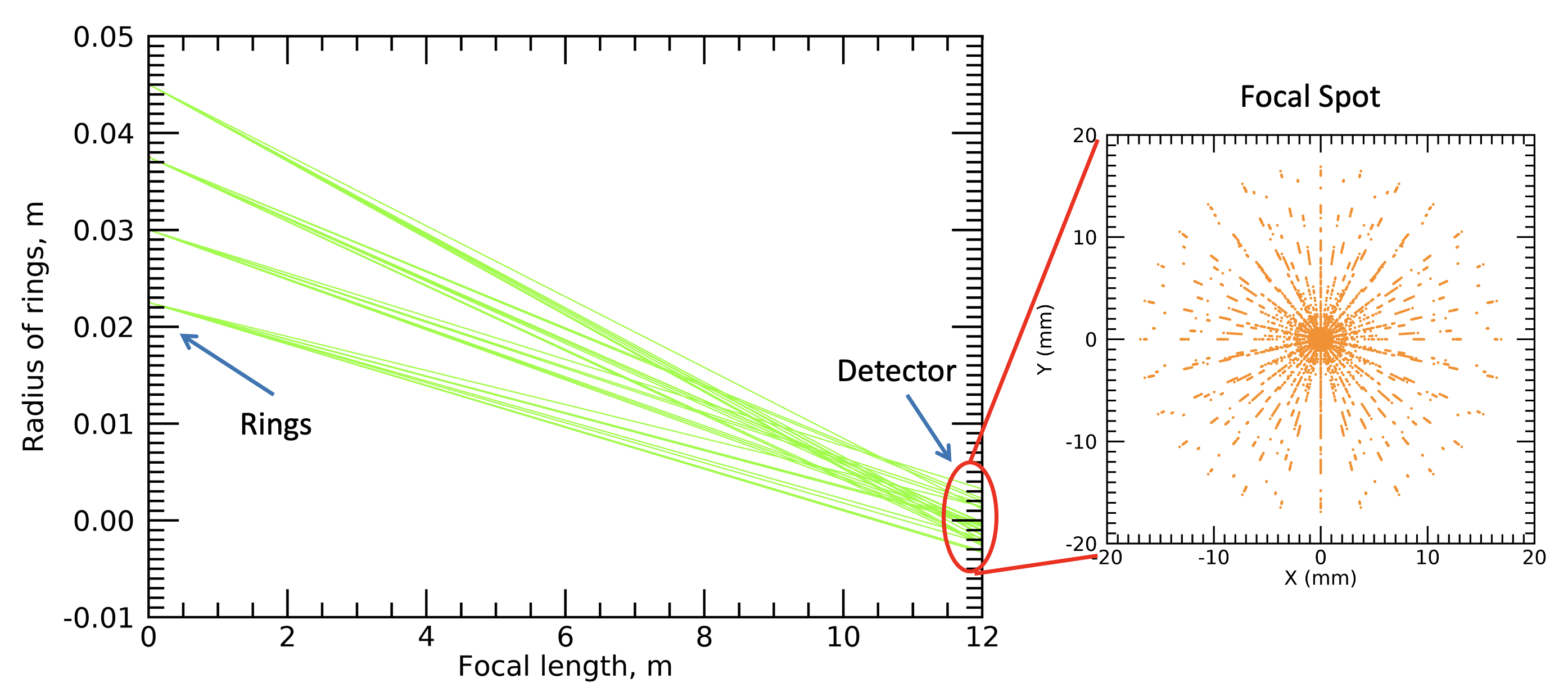
For this study, we re-created the -ray tracing code of the concentrator for a 12 m focal length. The lens could be made of four concentric rings of channeling segments, with ring radii of 2.25, 3, 3.75, and 4.5 cm and lengths of 2.1, 2.7, 3.5, and 4.6 cm, respectively [47]. Each ring would use 1 cm-wide, 7.5 mm-thick segments. The channeling multilayers are made of alternating magnetron-sputtered layers of 30 nm W and 150 nm Si and have total thickness of 5.4 m each. The channeling segments would have a total mass of 0.5 kg.
Altogether, the concentrator would produce a 3.5 cm diameter focal spot. The channeling optics would have a field of view with an angular radius of 4.47 arcmin (Fig. 3). Shirazi et al. discuss Cadmium Zinc Telluride (CZT) and Si detectors with a few cm2 of detection area as focal plane instrumentation [48]. The 511-CAM setup would be an excellent fit with such channeling optics, improving greatly upon the energy resolution of the CZT and Si detectors.
4 The Focal Plane Instrumentation for the 511-CAM
4.1 Microcalorimetric -Ray Detectors
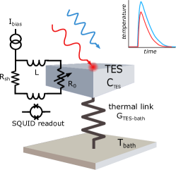
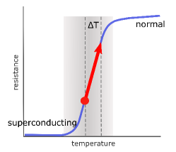
A microcalorimeter detector operates at 100 mK temperatures and records -rays via the measurement of the temperature transients that the -rays cause when they strike the detector absorbers (see Fig. 4, left panel). Each absorber is thermally coupled to a Transition Edge Sensor (TES), which is a thin superconducting film that works as a thermometer. The TES is biased at the lower end of its superconducting-to-normal transition. Owing to the sharpness of the transition, a tiny temperature change translates into a large change of the current allowed through the TES (Fig. 4, right panel).
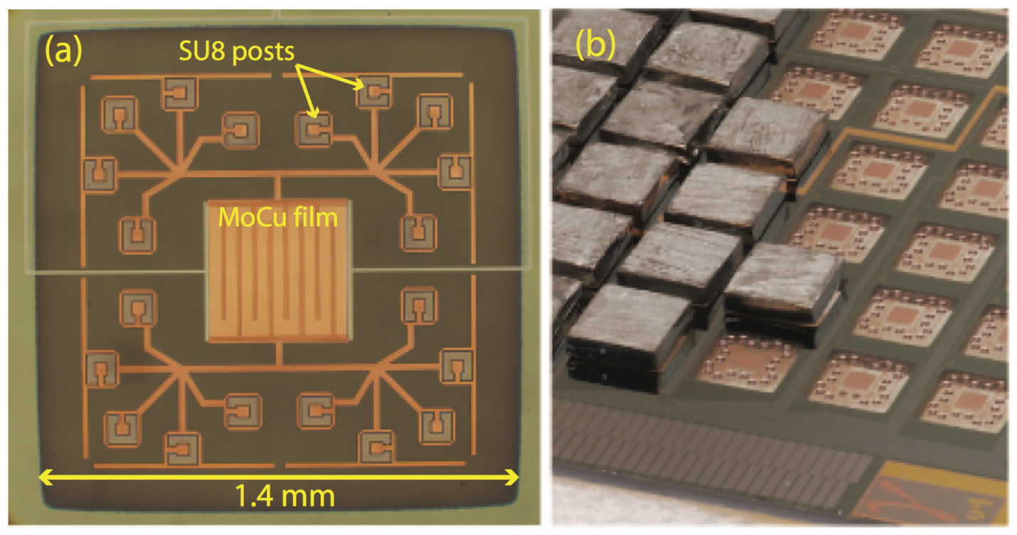
The NIST group has developed large microcalorimetric -ray detector arrays that are well-suited for NASA’s balloon-borne and space-borne astrophysics missions. The SLEDGEHAMMER detectors and their successors use cubic-millimeter-sized absorbers attached to TES sensors, and feature a fully scalable microwave readout scheme. Figure 5 shows the key components of the SLEDGEHAMMER detectors:
-
1.
The proximity effect is used to make MoCu (or MoAu) transition edge sensors with transition temperatures tailored to 100 mK (left panel).
-
2.
Sn absorbers are mounted on SU8 epoxy pillars that mechanically support the absorbers and establish the thermal link between the absorbers and the TES sensors (center panel).
-
3.
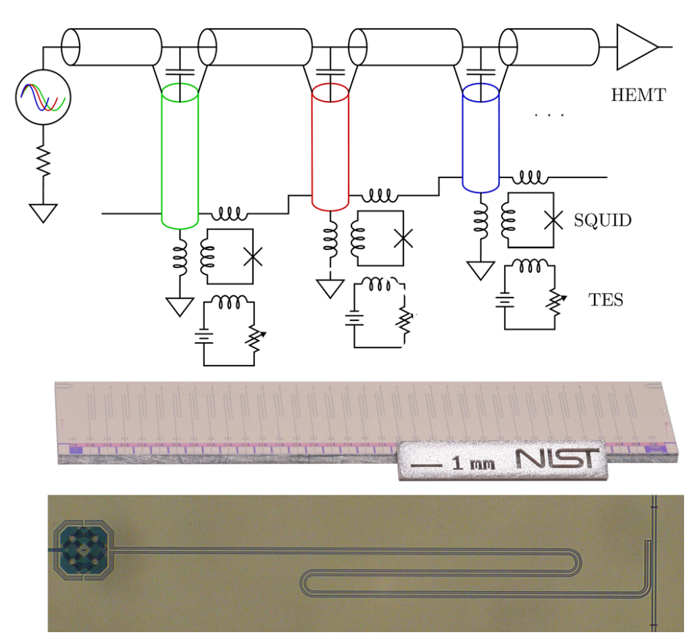
Each TES is read out by a Superconducting Quantum Interference Device (SQUID) that is AC-coupled to a GHz microwave resonator (right panel).
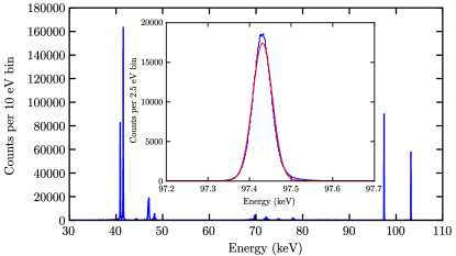
A 250-500 pixel detector box can then be read out with a single microwave feedline interrogating the resonators of all the pixels. The SQUIDs are operated with a modulated magnetic field flux bias, enlarging the dynamic range that can be satisfactorily sampled with the SQUIDs. The microwave multiplexing is ideally suited for astronomical applications, where many pixels are needed and complexity and mass need to be minimized while achieving a high degree of ruggedness. The SLEDGEHAMMER detectors, used with 1.451.450.38 mm Sn pixels, achieve an energy resolution of 55 eV FWHM over much of their dynamic range (Fig. 6) [15, 16, 17].
4.2 Optimization of the 511-CAM Focal Plane Instrumentation
Whereas different absorber materials have been tested extensively for X-ray micro-calorimeters, fewer studies have been completed for -ray microcalorimeters[52, 53]. Given that the performance of -ray microcalorimeters is limited by phonon noise that scales with the heat capacitance of the absorbers, the selection of an absorber material with low specific heat capacity is particularly important for these -ray detectors.
We consider four materials as options for the 511-CAM absorbers: Sn (the material currently used on the SLEDGEHAMMER detectors), Ta, Bi, or a Bi0.57-Sn0.43 alloy (see Table 1).
| Mate-rial | density [g/cm3] | [cm2/g] | [cm2/g] | [J/K/m3] | Refs | Comments | |
|---|---|---|---|---|---|---|---|
| Sn | 50 | 7.31 | 1.64 | 7.73 | 1.3 | [54, 15, 16, 52, 17, 53] | Currently used for SLEDGEHAMMER |
| Bi | 83 | 9.78 | 8.62 | 7.93 | 3.7 | [55, 56, 54, 57] | 511-CAM reference design |
| Ta | 72 | 16.6 | 5.71 | 7.81 | 1.0 | [52, 53] |
Potential issue:
H-contamination, which may increase the heat capacity measured |
| BiSn | 69 | 8.6 | 5.62 | 7.85 | tbd | none | 57% Bi, 43% Sn |
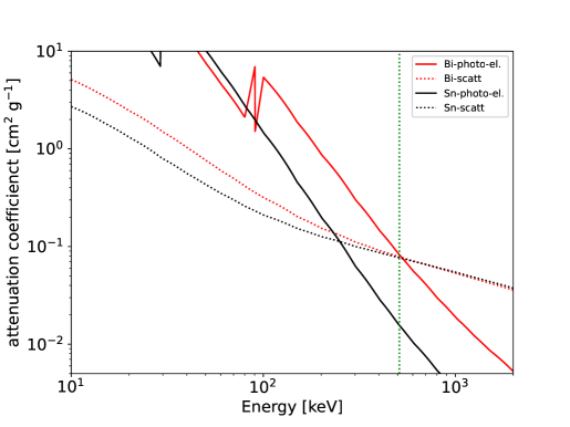
Figure 7 compares the photoelectric effect and scattering cross-sections of Sn and Bi in the 10 keV to 2 MeV energy range. Whereas the 511 keV Compton scattering cross-sections are similar for both materials, the photoelectric cross-section of Bi is 5.3 times larger than that of Sn. Photoelectric effect events, compared to Compton scattering events, are particularly valuable, since they lead to a smaller number of interactions and thus yield the better energy resolution. In this regard, Bi is a superior choice to Sn.
Another key property of an absorber material is the heat capacity. The fundamental limit on the energy resolution of a microcalorimetric detector is given by
| (1) |
Here, is the Boltzmann constant, is the temperature of the absorber, and is the heat capacitance of the absorber and TES. The parameter characterizes the steepness of the superconductivity-to-normal transition. The parameter depends on the heat transport between the TES electrons and the thermal bath [59]. Bi beats Sn as an absorber material for the 511-CAM in this heat capacity regard as well, given that the product of the volumetric heat capacitance times the photoelectric effect absorption length is 4.4 J K-1 m-2 and 1.1 J K-1 m-2 for Bi and Sn, respectively (see [54] for the heat capacitance of Bi). As seen in the formula above, the lower the heat capacitance, the better the energy resolution. Bi is furthermore preferred over Si as it offers a 5 times higher ratio of photoelectric effect to Compton scattering cross section, leading to a smaller number of interactions, and thus to better energy resolutions.
In terms of fabrication, we will use Bi cubes made from high-purity Bi sheets [55, 56, 57]. The Bi sheets can be obtained from companies such as those listed in the references [60, 61, 62].
Possible alternatives to Bi include Ta and Bi0.57Sn0.43. Like Bi, Ta exhibits a lower heat capacitance per area than Sn and achieves excellent resolutions at X-ray energies. For example, a microcalorimeter with small Ta absorbers of dimensions 0.5 mm 0.5 mm 0.3 mm has been shown to achieve a 445 eV FWHM energy resolution at 662 keV, thus solidly outperforming HPGe detectors. Even though this study measured the capacity of Ta to be higher than theoretically-calculated, it also notes that H-adsorption by Ta may have led to this higher heat capacity. This factor, along with vibrational noise from the dilution refrigerator, potentially contributes to the slightly worse-than-expected energy resolution. [53]. The motivation for using Bi0.57Sn0.43 is to make an absorber material that combines the high stopping power of Bi with the low heat capacitance of a superconductor that transitions at a higher, easier temperature. While the transition temperature of Sn at ambient pressures is 3.72 K, that of Bi is estimated to be 1.3 mK [63, 64]; Prakash et al. reported 0.53 mK [65]. The transition temperature hardly changes from 3.7 K across the alloy series until the alloy contains 90% Bi or more [66]. Thus, one could include substantial amounts of Bi in the alloy (with its higher photoelectric cross-sections) without significantly budging the more ideal, higher superconducting transition temperature.
However, yet another crucial figure of merit is the energy resolution per triggered pixel. Here, we provide an initial estimate of the projected energy resolution achievable if we focus on the possibility of using Bi as the absorber material. The 511-CAM will adopt the second-generation absorber/TES layout with mm2 footprint absorbers. Scaling the 55 eV FWHM energy resolution of the SLEDGEHAMMER detectors with the square root of the heat capacitance of the absorbers (Equation 1), we estimate that the 511-CAM would achieve a per-pixel energy resolution of 230 eV FWHM. Given the heat capacity of the Bi absorbers, we expect that 511 keV photons will cause a similar temperature excursion in the Bi absorbers as 30 keV photons do in the current absorbers. Saturation caused by the TES being heated to normal conductivity will thus not be an issue. This energy resolution improves dramatically over the best theoretically possible (Fano factor limited) 511 keV energy resolution of 900 eV FWHM of HPGe detectors.
5 Case study: a balloon-borne 12 m focal length 511-CAM mission
The 511-CAM technology enables missions with different -ray optics, focal lengths, and field of views. In this section, we discuss an exemplary balloon-borne mission. Long Duration Balloon (LDB) flights and Ultralong Duration Balloon Flights (ULDB) can be as long as 55 days and 100 days, respectively. The LDB flights typically reach altitudes of 38 km.
The design uses a 12 m focal length channeling concentrator (Fig. 8). The 511-CAM mission inherits XL-Calibur’s 12 m optical bench design, which uses carbon fiber tubes, Al joints, and Al honeycombs [36]. This setup draws from the designs of the XL-Calibur hard X-ray polarimetry mission scheduled for launches in summer 2022 and 2024, as well as the ASCENT mission proposed to the 2020 Pioneers opportunity [67, 68]. ASCENT employs a single- but larger-area SLEDGEHAMMER-type focal plane detector to map the 44Ti hard X-ray lines from supernova remnants such as Cas-A.
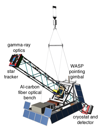
The XL-Calibur optical bench has a mass of 300 kg, and is designed for a 16 factor of safety to guarantee that it survives the parachute deployment and landing after the balloon flight. The telescope is pointed with the Wallops Arc-Second Pointer WASP, achieving a pointing stability of better than 1 arcsec [69]. The XL-Calibur science payload includes a 65 kg X-ray mirror and a 70 kg detector (made of Cadmium Zinc Telluride pixels), active shield (BGO), and readout (CPUs, various electronics) assembly. A 511-CAM mission would require somewhat heavier components, i.e., a 250 kg cryostat, detector, and shield assembly instead of the 70 kg one used for XL-Calibur.
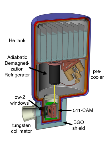
The detector is operated inside a wet LHe cryostat. We are considering two refrigerator options for cooling the detectors to 85 mK temperatures. The first option uses an Adiabatic Demagnetization Refrigerator (ADR) [70]; the second option uses a mini-Dilution Refrigerator (mini-DR) [71]. Whereas Fig. 8 shows the ADR solution, we are currently building a prototype for the mini-DR solution. The mini-DR achieves an excellent 10 K Root Mean Square (RMS) temperature stability, even when the unit experiences continuous tilting (as required for a unit in the focal plane of a balloon borne telescope) [72]. The temperature stability is comparable to the 4 K stability routinely achieved with ADRs [73]. For details of the mini-DR control, see Table 1 of [72]. Independent of the refrigerator solution, the only cables going to just one 511-CAM detector array are four coax cables (two “in” and two “out”, sufficient for the readout of all 82222 3,872 pixels), and two twisted-pair cables, one for the TES biases and one for the SQUID flux ramps. The expected heat dissipation of the 511-CAM of 1.2 W is dominated by the shunt resistors providing the TES biases. This power is below the cooling power provided by the pre-cooled ADR and the mini-DR.
The detector is shielded against cosmic rays and their daughter products with a passive tungsten shield at the inside of the cryostat and an active BGO shield at the outside. Magnetic shielding is provided by a superconducting niobium shield and a 0.062-inch thick Amumetal 4K shield. The SLEDGEHAMMER SQUIDs are designed to be highly gradiometric, making them nominally insensitive to uniform magnetic fields. In practice, this means that a SQUID with a footprint of 40,000 m2 shows an effective pickup area of only m2. We estimate that the magnetic fields do not affect the energy resolution of the 511-CAM, even during re-pointings of the instrument. The detector will see the gamma-ray sky through a suitable window. Whereas a thorough optimization still needs to be performed, we note that a possible solution could be a Light Element X-ray High Transmission (LEX-HT) window from Luxel. The window can be mounted on an ISO 100 flange with a 25.4 mm aperture, to let the -rays in. The filter is made of a 110 nm Al / 200 nm LUXFilm Polyimide film, secured with a stainless-steel ring, to block photons coming from a variety of temperatures from reaching the inside of the cryostat [74]. Since Al is a broadband IR-blocking material, it does not require precise tuning of its geometry or thickness to block the blackbody radiation emitted by any given temperature. Thicker windows-filter combinations may still give suitable 10 keV transmissivities while being mechanically more rugged.
The detector gain (i.e., the relation between the true photon energy and the detected signal) may drift with time owing to thermal contributions and amplifier contributions [75]. As mentioned above, we expect that we can keep the temperature of the cold head stable to within 4-10 K RMS [73, 72], and to correct for gain variations based on in-flight calibrations with a radioactive 133Ba source. This source emits -rays at 80.9971 keV (34.06%), 276.398 keV (7.164%), 302.853 keV (18.33%), 356.017 keV (62.05%), and 383.851 keV (8.94%). On the ground, before launch, we will calibrate by examining how the lines from both the 133Ba source and a 22Na source (which emits 511 keV -rays) change with respect to the gain, in order to know how the line changes at 511 keV given a certain change in the 133Ba lines during flight [73]. Note that the 133Ba source contributes background mainly below its 383.851 keV highest-energy -ray line, well below the 511-keV energy range of interest.
Detailed descriptions of the cold and warm detector readout electronics and the data analysis methods can be found in [76, 17, 77, 78]. Whereas our current lab system uses the Reconfigurable Open Architecture Computing Hardware ROACH2 platform [77] to interrogate the detectors with microwave tones and to digitize the detector output, we are currently transitioning to using Xilinx’s Zynq UltraScale Radio Frequency System-on-Chip (RFSoC) [79]. The RFSoC operates at GHz frequencies without the need to downsample and upsample the signals.
During Long Duration Balloon flights, data can be telemetered to the ground via Tracking and Data Relay Satellite System (TDRSS) at typical rates of 800 kbit s-1. Scaling the cosmic ray and atmospheric background measured with the XL-Calibur mission [80] according to the 511-CAM and XL-Calibur detector mass, we expect a 15 keV background rate of 60 Hz. Choosing a calibration source that generates an equal rate of calibration events, and accounting for the fact that the signal rate is negligible, we predict a detection rate of 120 Hz, with each event generating 4 kBytes of data. We envision the storage of all the raw data on a solid state disk located on the balloon gondola. An on-board PC 104 computer will be used to perform on-board processing of the data and will send, for each event, 20 Bytes of summary information (pixel number, trigger time, and reconstructed event amplitude) to the ground. The telemetered data will be used for system health checks.
We are currently preparing for the test of the mini-DR described in [72] and a 36-pixel prototype TES array on a one-day stratospheric balloon flight from Fort Sumner (NM) in Fall 2023 or Fall 2024. A detailed description of the DR-TES (Dilution Refrigerator-Transition Edge Sensor) payload, including the cryostat and detector design, the control, data acquisition, and telemetry software, the warm readout electronics, and the detector calibration, will be given in forthcoming papers.
6 Simulations of the focal plane detector
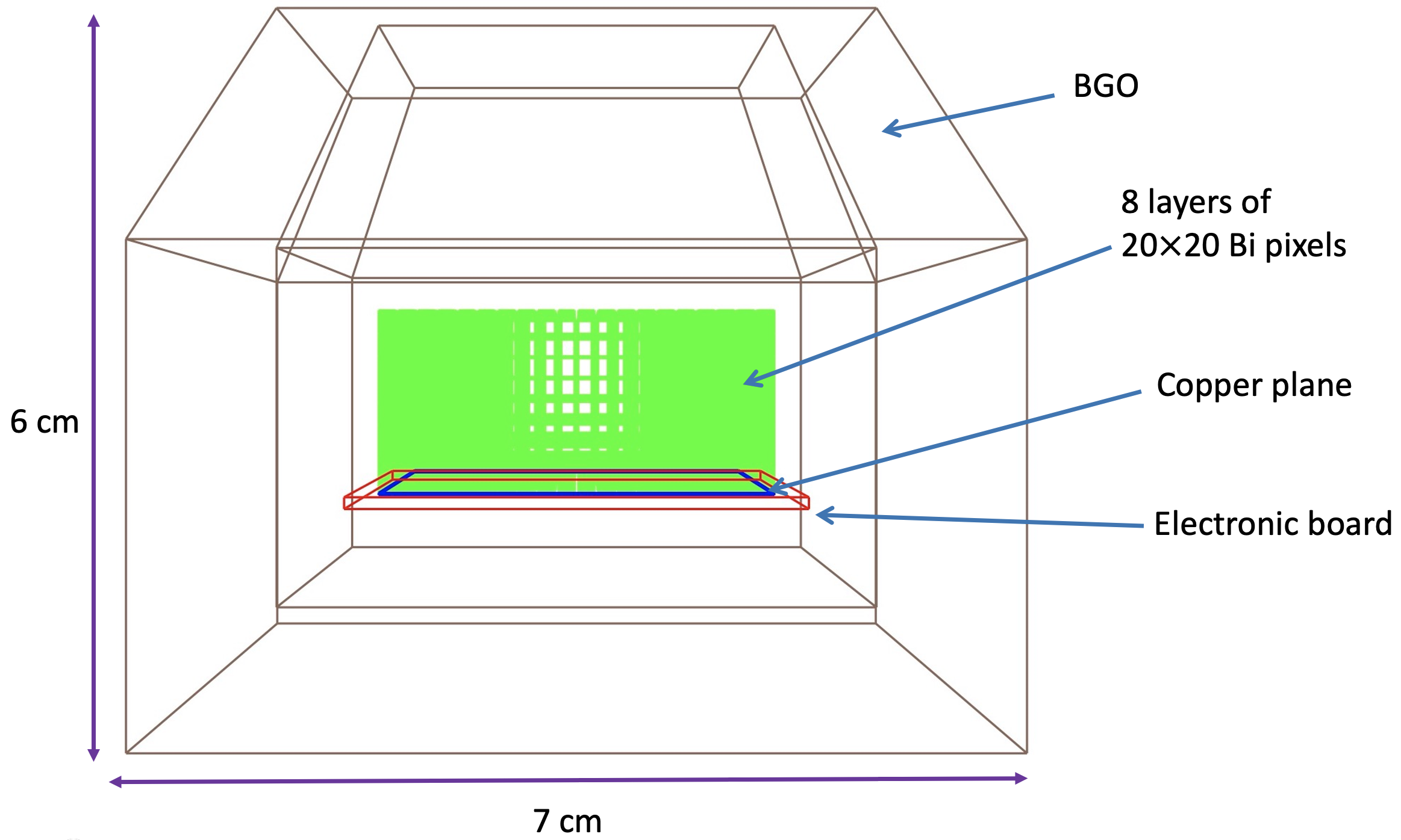
We simulated the performance of the 511-CAM technology described in this study, as a potential focal plane detector for the -ray concentrator, using the “MEGAlib” software tools [81]. We created a realistic geometry and described an idealized mass model for a simple detector, neglecting much of the passive material between detector layers. Note that the passive materials (carrier boards, copper planes, copper traces, TES sensors, SQUIDs, and resonator circuitry) are either low-Z or are very thin (m) and absorb much less energy than the 2 mm thick Bi absorbers. We assumed a reference configuration that uses 8 detector planes, each carrying 2020 Bi pixels (1.451.452 mm), which covers a 3.473.47 cm2 focal plane area. We chose to make the 511-CAM out of 8 layers of Bi. This choice results in absorbing 93% of the photons that hit the absorbers rather than the gaps between absorbers. We assume a per-pixel energy threshold of 1.2 keV. Although this trigger threshold is lower than the anticipated lower end of our dynamical range, the threshold barely affects the results, as most energy deposits will far exceed any likely threshold values. An active BGO shield surrounding the detector, 5 cm thick at the bottom and 2 cm thick on the sides, is included as the instrument shielding used to greatly reduce the background. An energy resolution of 10 keV and a trigger threshold of 70 keV is used for the BGO (Fig. 9). In the simulations, the BGO shield has a cylindrical hole, on the top, of the size of the focal spot that allows -rays to enter. The simulations neglect the Nb and cryoperm (A4K) magnetic shields for now.
Then, we utilized a 511 keV near-field source whose profile is given by a concentrated radial beam onto the focal plane. An effective observation time of 1 Ms has been assumed for a balloon flight, and the flux was modified for the effects of atmospheric absorption. The resulting output file contained the simulated interaction information, including the time, type, position, and energy deposition of each interaction.
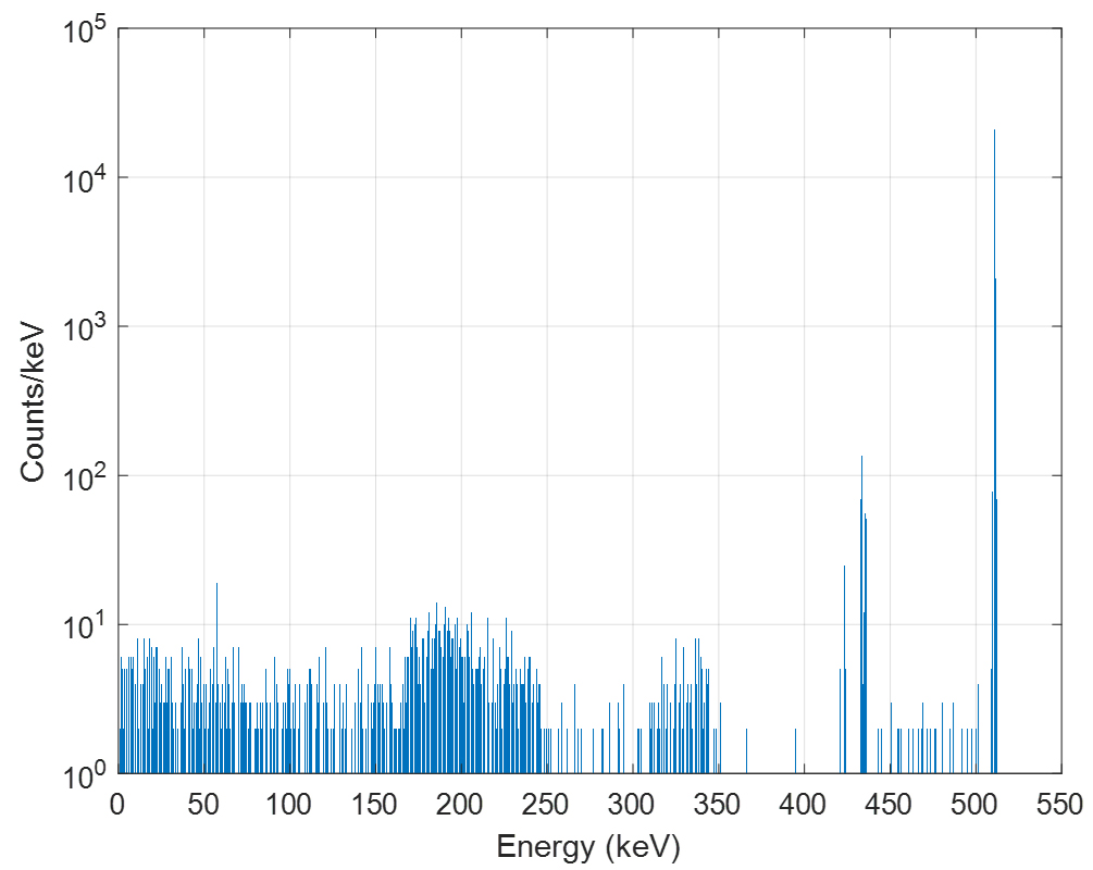
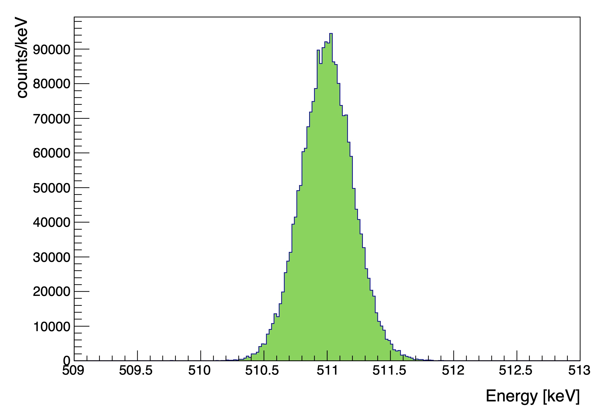
These simulations allow us to determine the detector performance and optimize the instrument design with respect to the desired scientific objectives, including the effect of the gaps between absorbers. The resulting 511 keV energy spectrum is shown in Fig. 10. The energy spectrum shows a pronounced peak centered on 511 keV. The FWHM energy resolution is 390 eV, and a total of 93% of the detected 511 keV events have reconstructed energies between 510.3 keV and 511.8 keV. The 511-CAM thus excels through its energy resolution: the 511-CAM energy resolution of 390 eV is 11 times better than the 4.3 keV resolution of COSI. Another strength of the 511-CAM is the 93% efficiency of the detected events reconstructed within that energy resolution.
We note that most photoelectric effect events deposit their energy in exactly one pixel. As noted above, these events have a particularly good energy resolution. Even though one-pixel events are not suitable for a Compton imaging analysis (which analyzes the energy deposited in two or more pixels, together with the information about the location of these pixels), one-pixel events are expected to have a low background. For example, for the X-Calibur experiment, using only single-pixel events removes 99% of the background. We can furthermore use self-shielding (i.e., discarding events triggering the edge pixels) to suppress one-pixel background events. For events with 2 triggered pixels, we can use Compton imaging to suppress events which cannot possibly come from the -ray optics [82, 83].
A possible design optimization is the use of “staggered detector layers” in which the layers are offset slightly to reduce the loss of photons that hit the gaps of the detector assembly. A full tradeoff study that accounts for the gain of detected photons but also evaluates the effect on the energy resolution is outside the scope of this paper.
7 Predicted performance of a balloon-borne 511-CAM mission
One of the key elements of the detector response is the instrument efficiency or effective area, which, for the 511-CAM, consists of both lens and detector efficiency. The simulation code calculates the lens channeling efficiency by using the relation
| (2) |
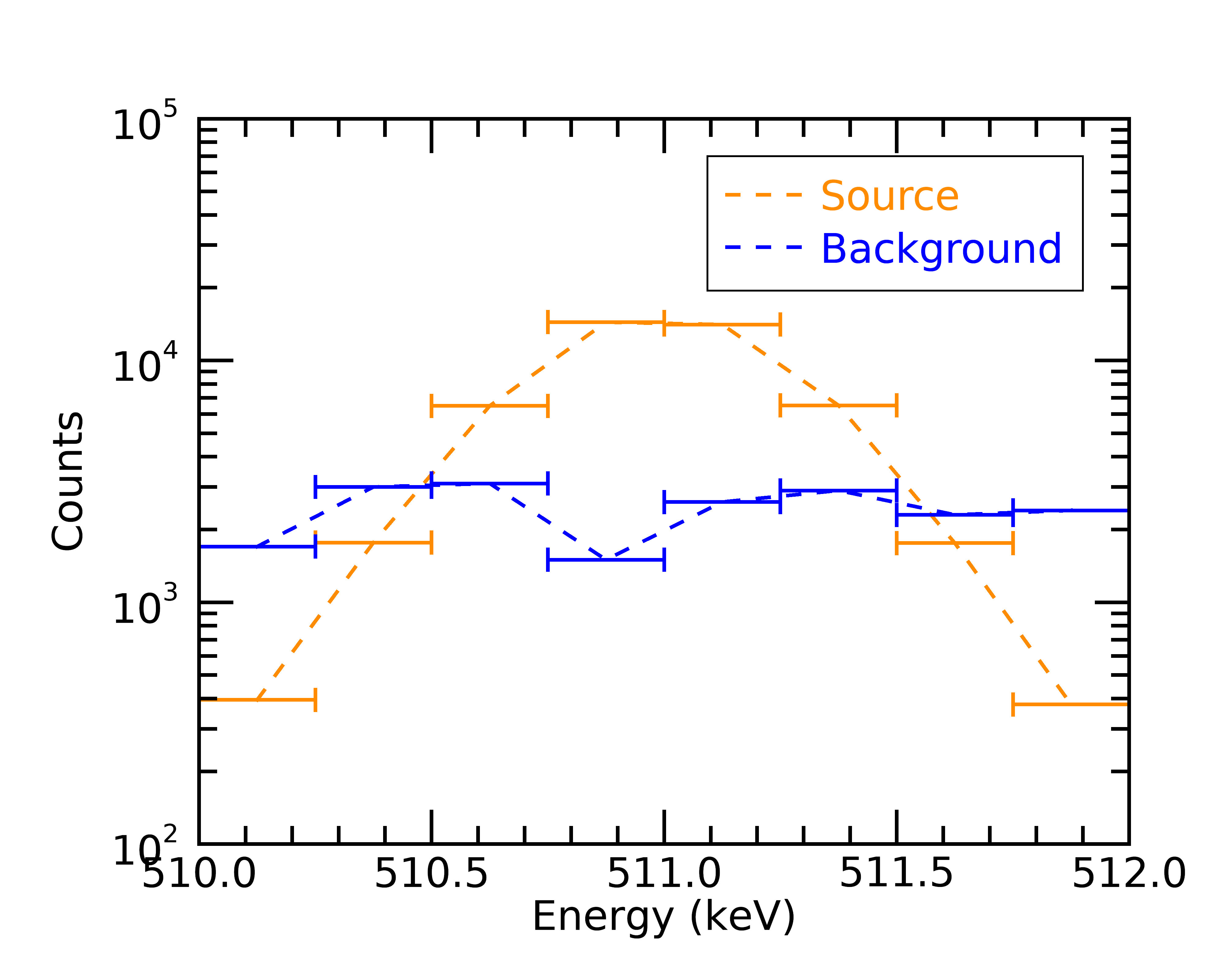
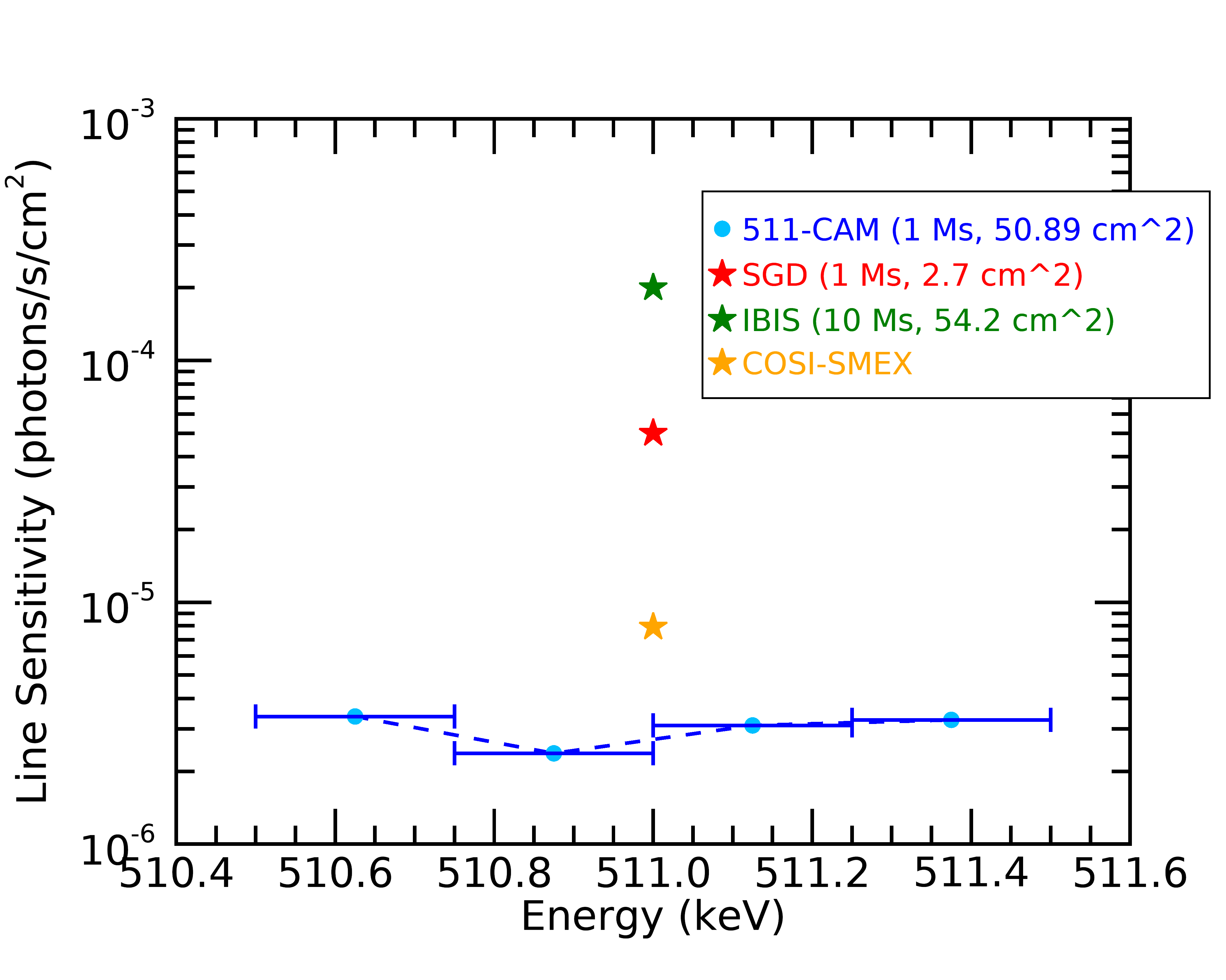
The open fraction term is equivalent to the ratio of spacer layer thickness to the period of bi-layers. Our 511-CAM simulation shows that for the 9 cm diameter lens, the resulting effective area of a balloon-borne mission at 511 keV is 50.89 cm2. To predict the sensitivity of the detector, we also modeled the dominant background components during a balloon flight and their effects on instrument performance. We followed the model developed by Gehrels [84] for shield leakage of -ray background. The results are given for a column density of 3.5 g/cm2 of rest-atmosphere. Figure 11 shows the source and background counts (left panel) and the calculated sensitivity (right panel) at 3 confidence level. The estimated detector response under the concentrated point source and background indicates that 511-CAM, combined with the -ray concentrator, can achieve a sensitivity better than current instruments – even for the most conservative estimate of the per-pixel energy resolution. The development of SLEDGEHAMMER detectors with BiSn absorbers could give much better energy resolutions. The background fluctuations scale with the square root of the energy resolution. Thus, an energy resolution improved by a factor of 4 would improve the sensitivity by a factor of 2. The key assumptions and results of these channeling optics/511-CAM simulations are listed in Table 2.
8 Discussion
| Parameter | Value |
|---|---|
| Number of channeling rings | |
| Radius of rings | cm |
| Multilayer bending angles | |
| Multilayer lengths | cm |
| Multilayer width | cm |
| Total number of multilayers | |
| Focal length | m |
| Focused beam diameter | cm |
| Absorber material | |
| Pixel volume | |
| Pixel array | |
| FWHM pixel resolution | keV |
| Trigger threshold | keV |
| Observation duration | Ms |
| Flux | ph/s |
| FWHM energy resolution | keV |
| Channeling optics transmissivity | |
| Effective area of optics | |
| Detection efficiency of TES stack, incl. gaps |
This paper discusses the new 511-CAM mission concept based on a stack of microcalorimetric detectors that combine mm3-sized absorbers with Transition Edge Sensors. The pointed mission would complement wide-field-of-view missions such as COSI [7, 8], COSI-X [85], or AMEGO-X [86]. With the conservative assumption of using Bi absorbers, the 511-CAM mission would achieve a per-pixel energy deposit resolution of 230 eV FWHM and a 511 keV gamma-ray energy resolution of 390 eV FWHM. We argue that high-Z absorbers with lower heat capacities, such as the Bi0.57-Sn0.43 alloy, could lead to further marked improvements in energy resolution. The energy resolution of a 511-CAM-type mission directly impacts the sensitivity of a background-limited 511 keV gamma-ray mission.
The proposed balloon-borne mission would be ideally suited to detect point sources of 511 keV emission, offering improved localization of these sources and precise line-of-sight velocity measurements. If the 511 keV emission from the galactic center region is truly diffuse, the mission could still detect it, but the estimated detection rate would be low, i.e., 0.17 photons per day over a background of 0.03 photons per day.
A mission with a broad energy bandpass might be more attractive than a mission focusing exclusively on the detection of the 511 keV line. The channeling optics discussed above inherently come with a broad bandpass, thus enabling the search for gamma-ray lines from various astrophysical sources. Alternatively, a broadband mission could be built by combining a re-configurable Laue lens [87] with an extendable optical bench. One could envision multiple flights of such a mission, each one using a lens and focal length configuration optimized for a certain science goal.
Acknowledgements
HK thanks N. Barrière for the permission to use Fig. 1, and NASA for the support through the grants NNX16AC42G and 80NSSC18K0264. The authors acknowledge the helpful comments of two anonymous referees.
References
- [1] W. R. Purcell, L. X. Cheng, D. D. Dixon, et al., “OSSE Mapping of Galactic 511 keV Positron Annihilation Line Emission,” ApJ, 491, 725–748 (1997).
- [2] J. Knödlseder, P. Jean, V. Lonjou, et al., “The all-sky distribution of 511 keV electron-positron annihilation emission,” A&A, 441, 513–532 (2005).
- [3] E. Churazov, R. Sunyaev, S. Sazonov, et al., “Positron annihilation spectrum from the Galactic Centre region observed by SPI/INTEGRAL,” MNRAS, 357, 1377–1386 (2005).
- [4] G. Weidenspointner, G. Skinner, P. Jean, et al., “An asymmetric distribution of positrons in the Galactic disk revealed by -rays,” Nature, 451, 159–162 (2008).
- [5] L. Bouchet, J. P. Roques, and E. Jourdain, “On the Morphology of the Electron-Positron Annihilation Emission as Seen by Spi/integral,” ApJ, 720, 1772–1780 (2010).
- [6] E. Churazov, S. Sazonov, S. Tsygankov, et al., “Positron annihilation spectrum from the Galactic Centre region observed by SPI/INTEGRAL revisited: annihilation in a cooling ISM?,” MNRAS, 411, 1727–1743 (2011).
- [7] C. A. Kierans, S. E. Boggs, A. Zoglauer, et al., “Detection of the 511 keV Galactic Positron Annihilation Line with COSI,” ApJ, 895, 44 (2020).
- [8] T. Siegert, S. E. Boggs, J. A. Tomsick, et al., “Imaging the 511 keV Positron Annihilation Sky with COSI,” ApJ, 897, 45 (2020).
- [9] M. H. Chan and C. H. Leung, “Constraining dark matter by the 511 keV line,” MNRAS, 479, 2229–2234 (2018).
- [10] N. Prantzos, C. Boehm, A. M. Bykov, et al., “The 511 keV emission from positron annihilation in the Galaxy,” Reviews of Modern Physics 83, 1001–1056 (2011).
- [11] P. von Ballmoos, H. Halloin, J. Evrard, et al., “CLAIRE: First light for a gamma-ray lens,” Experimental Astronomy 20, 253–267 (2005).
- [12] N. Barrière, J. Rousselle, P. Von Ballmoos, et al., “Experimental and theoretical study of the diffraction properties of various crystals for the realization of a soft gamma-ray laue lens,” Journal of Applied Crystallography 42(5), 834–845 (2009).
- [13] R. K. Smither, “Invited Review Article: Development of crystal lenses for energetic photons,” Review of Scientific Instruments 85, 081101 (2014).
- [14] N. Barrière, P. von Ballmoos, L. Natalucci, et al., “Laue lens: the challenge of focusing gamma rays,” in Society of Photo-Optical Instrumentation Engineers (SPIE) Conference Series, Society of Photo-Optical Instrumentation Engineers (SPIE) Conference Series 10566, 1056603 (2017).
- [15] D. A. Bennett, R. D. Horansky, D. R. Schmidt, et al., “A high resolution gamma-ray spectrometer based on superconducting microcalorimeters,” Rev. Sci. Instrum. 83, 093113–093113–14 (2012).
- [16] O. Noroozian, J. A. B. Mates, D. A. Bennett, et al., “High-resolution gamma-ray spectroscopy with a microwave-multiplexed transition-edge sensor array,” Appl. Phys. Lett. 103, 202602 (2013).
- [17] J. A. B. Mates, D. T. Becker, D. A. Bennett, et al., “Simultaneous readout of 128 X-ray and gamma-ray transition-edge microcalorimeters using microwave SQUID multiplexing,” Appl. Phys. Lett. 111, 062601 (2017).
- [18] T. Siegert, R. Diehl, A. C. Vincent, et al., “Search for 511 keV emission in satellite galaxies of the Milky Way with INTEGRAL/SPI,” A&A, 595, A25 (2016).
- [19] K. Lawson and A. Zhitnitsky, “Quark nugget dark matter: no contradiction with 511 keV line emission from dwarf galaxies,” J. Cosmology Astropart. Phys., 2017, 049 (2017).
- [20] R. J. Wilkinson, A. C. Vincent, C. Bœhm, et al., “Ruling out the light weakly interacting massive particle explanation of the Galactic 511 keV line,” Phys. Rev. D 94(10), 103525 (2016).
- [21] N. Sabti, J. Alvey, M. Escudero, et al., “Refined Bounds on MeV-scale Thermal Dark Sectors from BBN and the CMB,” JCAP 01, 004 (2020).
- [22] Y. Ema, F. Sala, and R. Sato, “Dark matter models for the 511 keV galactic line predict keV electron recoils on Earth,” Eur. Phys. J. C 81(2), 129 (2021).
- [23] R.-G. Cai, Y.-C. Ding, X.-Y. Yang, et al., “Constraints on a mixed model of dark matter particles and primordial black holes from the galactic 511 keV line,” JCAP 03, 057 (2021).
- [24] C. Keith and D. Hooper, “511 keV excess and primordial black holes,” Phys. Rev. D 104(6), 063033 (2021).
- [25] P. S. Coppi, “Time-dependent models of magnetized pair plasmas,” MNRAS, 258, 657–683 (1992).
- [26] A. C. Fabian, A. Lohfink, E. Kara, et al., “Properties of AGN coronae in the NuSTAR era,” MNRAS, 451, 4375–4383 (2015).
- [27] T. Vuillaume, G. Henri, and P. O. Petrucci, “A stratified jet model for AGN emission in the two-flow paradigm,” A&A, 620, A41 (2018).
- [28] M. Petropoulou, L. Sironi, A. Spitkovsky, et al., “Relativistic Magnetic Reconnection in Electron-Positron-Proton Plasmas: Implications for Jets of Active Galactic Nuclei,” ApJ, 880, 37 (2019).
- [29] T. Siegert, R. Diehl, J. Greiner, et al., “Positron annihilation signatures associated with the outburst of the microquasar V404 Cygni,” Nature, 531, 341–343 (2016).
- [30] F. Harrison, D. Stern, D. Alexander, et al., “Mission Concept White Paper for Next NASA X-Ray Astronomy Mission,” (2001).
- [31] R. Diehl, “About cosmic gamma ray lines,” in Exotic Nuclei and Nuclear/particle AstroPhysics (VI). Physics with Small Accelerators, American Institute of Physics Conference Series 1852, 040004 (2017).
- [32] O. Korobkin, A. M. Hungerford, C. L. Fryer, et al., “Gamma Rays from Kilonova: A Potential Probe of r-process Nucleosynthesis,” ApJ, 889, 168 (2020).
- [33] H. Halloin, “Laue diffraction lenses for astrophysics: From theory to experiments,” Experimental Astronomy 20, 171–184 (2005).
- [34] P. von Ballmoos, H. Halloin, J. Evrard, et al., “CLAIRE: First light for a gamma-ray lens,” Experimental Astronomy 20, 253–267 (2005).
- [35] F. Kislat, B. Beheshtipour, P. Dowkontt, et al., “Design of the Telescope Truss and Gondola for the Balloon-Borne X-ray Polarimeter X-Calibur,” J. Astron. Instrum. 6, 1740003 (2017).
- [36] Q. Abarr, H. Awaki, M. G. Baring, et al., “XL-Calibur - a second-generation balloon-borne hard X-ray polarimetry mission,” Astroparticle Physics 126, 102529 (2021).
- [37] N. Barriere, P. von Ballmoos, G. Skinner, et al., “MAX: Development of a Laue diffraction lens for nuclear astrophysics,” Nuclear Instruments and Methods in Physics Research A 567, 333–336 (2006).
- [38] C. Wade, N. M. Barrière, J. A. Tomsick, et al., “Construction, characterization, and environmental testing of a Laue lens prototype using Fe and Al crystals,” Nuclear Instruments and Methods in Physics Research A 895, 135–143 (2018).
- [39] D. Girou, E. Ford, C. Wade, et al., “Design and modeling of a laue lens for radiation therapy with hard x-ray photons,” Physics in Medicine & Biology 66, 245007 (2021).
- [40] M. A. Kumakhov, “Channeling of photons and new X-ray optics,” Nuclear Instruments and Methods in Physics Research B 48, 283–286 (1990).
- [41] B. D. Ramsey, R. A. Austin, and R. Decher, “Instrumentation for X-Ray Astronomy,” Space Sci. Rev., 69, 139–204 (1994).
- [42] D. Della Monica Ferreira, F. E. Christensen, M. J. Pivovaroff, et al., “Hard x-ray/soft gamma-ray telescope designs for future astrophysics missions,” in Optics for EUV, X-Ray, and Gamma-Ray Astronomy VI, S. L. O’Dell and G. Pareschi, Eds., Society of Photo-Optical Instrumentation Engineers (SPIE) Conference Series 8861, 886116 (2013).
- [43] N. F. Brejnholt, M.-A. Descalle, R. Soufli, et al., “Next generation hard X-ray/soft gamma-ray optic design and implementation,” in Space Telescopes and Instrumentation 2014: Ultraviolet to Gamma Ray, T. Takahashi, J.-W. A. den Herder, and M. Bautz, Eds., Society of Photo-Optical Instrumentation Engineers (SPIE) Conference Series 9144, 914419 (2014).
- [44] V. V. Lider, “X-ray fluorescence imaging,” Physics Uspekhi 61, 980 (2018).
- [45] F. Shirazi, P. F. Bloser, J. E. Krzanowskic, et al., “Modeling and development of soft gamma-ray channeling,” in Space Telescopes and Instrumentation 2018: Ultraviolet to Gamma Ray, J.-W. A. den Herder, S. Nikzad, and K. Nakazawa, Eds., Society of Photo-Optical Instrumentation Engineers (SPIE) Conference Series 10699, 106995V (2018).
- [46] P. Korecki, T. P. Roszczynialski, and K. M. Sowa, “Simulation of image formation in x-ray coded aperture microscopy with polycapillary optics,” Optics Express 23, 8749 (2015).
- [47] F. Shirazi, P. F. Bloser, J. E. Krzanowski, et al., “Simulation and optimization of a soft gamma-ray concentrator using thin film multilayer structures,” in Society of Photo-Optical Instrumentation Engineers (SPIE) Conference Series, Society of Photo-Optical Instrumentation Engineers (SPIE) Conference Series 10399, 103991A (2017).
- [48] A. Takano, K. Maehata, N. Iyomoto, et al., “Simulation Model of Transmitted X-Rays in Polycapillary Optics for TES Microcalorimeter EDS System on Scanning Transmission Electron Microscope,” IEEE Transactions on Nuclear Science 65, 758–765 (2018).
- [49] F. Shirazi, Simulation and Optimization of a Soft Gamma-Ray Concentrator Using Thin-Film Multilayer Structures. PhD thesis, University of New Hampshire (2018).
- [50] P. F. Bloser, P. H. Aliotta, O. Echt, et al., “A soft gamma-ray concentrator using thin-film multilayer structures,” in Optics for EUV, X-ray, and Gamma-Ray Astronomy VII, Proc. SPIE 9603, 96031E (2015).
- [51] F. Shirazi, P. F. Bloser, J. S. Legere, et al., “Performance simulation of the soft gamma-ray concentrator,” Journal of Astronomical Telescopes, Instruments, and Systems 6, 024001 (2020).
- [52] T. Irimatsugawa, S. Hatakeyama, M. Ohno, et al., “High Energy Gamma-Ray Spectroscopy Using Transition-Edge Sensor With a Superconducting Bulk Tantalum Absorber,” IEEE Transactions on Applied Superconductivity 25, 2380173 (2015).
- [53] M. Ohno, T. Irimatsugawa, H. Takahashi, et al., “Superconducting Transition Edge Sensor for Gamma-Ray Spectroscopy,” IEICE Transactions on Electronics 100, 283–290 (2017).
- [54] A. D. Brown, S. R. Bandler, R. Brekosky, et al., “Absorber Materials for Transition-Edge Sensor X-ray Microcalorimeters,” Journal of Low Temperature Physics 151, 413–417 (2008).
- [55] D. Yan, R. Divan, L. M. Gades, et al., “Eliminating the non-Gaussian spectral response of X-ray absorbers for transition-edge sensors,” Applied Physics Letters 111, 192602 (2017).
- [56] D. Yan, R. Divan, L. M. Gades, et al., “Microstructure Analysis of Bismuth Absorbers for Transition-Edge Sensor X-ray Microcalorimeters,” Journal of Low Temperature Physics 193, 225–230 (2018).
- [57] R. Hummatov, J. S. Adams, S. R. Bandler, et al., “Quantum Efficiency Study and Reflectivity Enhancement of Au/Bi Absorbers,” Journal of Low Temperature Physics 199, 393–400 (2020).
- [58] “Element/compound/mixture selection.” https://www.physics.nist.gov/PhysRefData/Xcom/html/xcom1.html (2022).
- [59] K. D. Irwin, “An application of electrothermal feedback for high resolution cryogenic particle detection,” Applied Physics Letters 66, 1998–2000 (1995).
- [60] “Bismuth (bi) foil - material information.” http://www.goodfellow.com/E/Bismuth-Foil.html (2020).
- [61] “Bismuth bi.” https://www.edge-techind.com/category/Bismuth-Bi-143-1.html (2020).
- [62] “Materials.” https://vulcangms.com/materials/#m-bismuth (2020).
- [63] A. A. Valladares, V. Rodríguez, R. Hinijosa, et al., “Possible superconductivity in the bismuth iv solid phase under pressure,” Scientific Reports 8, 5946 (2018).
- [64] Z. Mata-Pinzón, A. Valladares, R. Valladares, et al., “Superconductivity in Bismuth. A New Look at an Old Problem,” PLOS ONE (2016).
- [65] O. Prakash, A. Kumar, A. Thamizhavel, et al., “Evidence for bulk superconductivity in pure bismuth single crystals at ambient pressure,” Science 355, 52–55 (2017).
- [66] D. E. Gordon and B. C. Deaton, “Superconductivity in metastable bismuth eutectic alloys,” Physics Letters A 27, 116–117 (1968).
- [67] F. Kislat, J. Legere, P. Daigneau, et al., “ASCENT – A Superconducting Energetic X-ray Telescope,” (2020). submitted to the Pioneers Announcement of Opportunity, NASA 20-Pioneers20-0016.
- [68] F. Kislat, D. Becker, D. Bennett, et al., “ASCENT - A balloon-borne hard X-ray imaging spectroscopy telescope using transition edge sensor microcalorimeter detectors,” arXiv e-prints , arXiv:2301.01525 (2023).
- [69] D. Stuchlik, “NASA Wallops Arc Second Pointer (WASP) System Development Project,” in 40th COSPAR Scientific Assembly, 40, PSB.1–51–14 (2014).
- [70] P. Wikus, J. S. Adams, Y. Bagdasarova, et al., “The Adiabatic Demagnetization Refrigerator for the Micro-X Sounding Rocket Telescope,” in Transactions of the Cryogenic Engineering Conference - CEC: Advances in Cryogenic Engineering, J. G. Weisend¡Extra1¿Ii¡/Extra1¿, Ed., American Institute of Physics Conference Series 1218, 633–640 (2010).
- [71] S. T. Chase, T. L. R. Brien, S. M. Doyle, et al., “Pre-cooling a 3He/4He dilutor module with a sealed closed-cycle continuous cooler,” in Materials Science and Engineering Conference Series, Materials Science and Engineering Conference Series 502, 012134 (2019).
- [72] R. Snodgrass, J. Ullom, and S. Backhaus, “Performance of a Miniature, Cold-Cycle Dilution Refrigerator at Tilt Angles between 0 and 30 Degrees,” Proceedings of the 22nd International Cryocooler Conference (ICC22), June 27-30, 2022, Pennsylvania, USA (2022). https://cryocooler.org/resources/Documents/C22/353.pdf.
- [73] P. Szypryt, G. C. O’Neil, E. Takacs, et al., “A transition-edge sensor-based x-ray spectrometer for the study of highly charged ions at the National Institute of Standards and Technology electron beam ion trap,” Review of Scientific Instruments 90, 123107 (2019).
- [74] Luxel, P.O. Box 1879 60 Saltspring Dr. Friday Harbor, WA 98250 USA, https:luxel.com, last accessed: 1/7/2023.
- [75] F. S. Porter, M. P. Chiao, M. E. Eckart, et al., “Temporal Gain Correction for X-ray Calorimeter Spectrometers,” Journal of Low Temperature Physics 184, 498–504 (2016).
- [76] J. A. B. Mates, The Microwave SQUID Multiplexer. PhD thesis, University of Colorado, Boulder (2011).
- [77] J. D. Gard, D. T. Becker, D. A. Bennett, et al., “A Scalable Readout for Microwave SQUID Multiplexing of Transition-Edge Sensors,” Journal of Low Temperature Physics 193, 485–497 (2018).
- [78] D. T. Becker, B. K. Alpert, D. A. Bennett, et al., “Advances in analysis of microcalorimeter gamma-ray spectra,” IEEE Trans. Nucl. Sci. 66(12), 2355–2363 (2019).
- [79] Xilinx Inc., “Zynq UltraScale+ RFSoC ZCU111 Evaluation Kit,” (2022). https://www.xilinx.com/products/boards-and-kits/zcu111.html, last accessed: 1/2/2023.
- [80] N. K. Iyer, M. Kiss, M. Pearce, et al., “The design and performance of the XL-Calibur anticoincidence shield,” arXiv e-prints , arXiv:2212.04139 (2022).
- [81] A. Zoglauer, R. Andritschke, and F. Schopper, “MEGAlib The Medium Energy Gamma-ray Astronomy Library,” New A Rev., 50, 629–632 (2006).
- [82] D. Xu, Z. He, C. E. Lehner, et al., “4-pi Compton imaging with single 3D position-sensitive CdZnTe detector,” in Hard X-Ray and Gamma-Ray Detector Physics VI, A. Burger, R. B. James, and L. A. Franks, Eds., Society of Photo-Optical Instrumentation Engineers (SPIE) Conference Series 5540, 144–155 (2004).
- [83] G. Daniel, O. Limousin, D. Maier, et al., “Compton imaging reconstruction methods: a comparative performance study of direct back-projection, SOE, a new Bayesian algorithm and a new Compton inversion method applied to real data with Caliste,” in European Physical Journal Web of Conferences, European Physical Journal Web of Conferences 225, 06006 (2020).
- [84] N. Gehrels, “Instrumental background in balloon-borne gamma-ray spectrometers and techniques for its reduction,” Nuclear Instruments and Methods in Physics Research Section A: Accelerators, Spectrometers, Detectors and Associated Equipment 239(2), 324–349 (1985).
- [85] A. Zoglauer, “The Path from COSI to COSI-X,” in Proceedings of the 7th International Fermi Symposium, 179 (2017).
- [86] H. Fleischhack and Amego X Team, “AMEGO-X: MeV gamma-ray Astronomy in the Multi-messenger Era,” in 37th International Cosmic Ray Conference. 12-23 July 2021. Berlin, 649 (2022).
- [87] N. Lund, “Wide band, tunable gamma-ray lenses,” Experimental Astronomy 51, 153–163 (2021).