Quantitative and realistic description of the magnetic potential energy of spin-torque vortex oscillators
Abstract
Understanding the dynamics of magnetic vortices has emerged as an important challenge regarding the recent development of spin-torque vortex oscillators. Either micromagnetic simulations or the analytical Thiele equation approach are typically used to study such systems theoretically. This work focuses on the precise description of the restoring forces exerted on the vortex when it is displaced from equilibrium. In particular, the stiffness parameters related to a modification of the magnetic potential energy terms are investigated. A method is proposed to extract exchange, magnetostatic and Zeeman stiffness expressions from micromagnetic simulations. These expressions are then compared to state-of-the-art analytical derivations. Furthermore, it is shown that the stiffness parameters depend not only on the vortex core position but also on the injected current density. This phenomenon is not predicted by commonly used analytical ansätze. We show that these findings result from a deformation of the theoretical magnetic texture caused by the current induced Ampère-Oersted field.
I Introduction
Magnetic vortices are one of the encountered magnetic ground states in soft ferromagnets of reduced dimensions. These non-uniform topologies are characterized by curling in-plane spins swirling around a small area called the vortex core, where the magnetization points out-of-plane. Such distribution results from a favorable trade-off between exchange and magnetostatic energies, arising for a wide range of nanodot aspect ratios.Metlov and Guslienko (2002) Two main topological parameters are typically used to describe a vortex,Guslienko (2006) namely the chirality (also called circulation or helicity) and the polarity . On the one hand, the chirality indicates whether the in-plane magnetization curls clockwise () or counterclockwise (). On the other hand, the polarity informs on the direction of the out-of-plane vortex core profile, which either points upwards () or downwards (). Due to their great stability,Hertel et al. (2007); Guslienko (2008); Hrkac et al. (2015) vortices have rapidly gained a lot of attention for prospective applications, notably when combined with spintronics.
Indeed, concomitantly to the advances in vortex dynamics understanding were investigated the first spin-torque nano-oscillators.Katine et al. (2000); Kiselev et al. (2003); Slavin and Tiberkevich (2009); Zeng et al. (2013) This type of device, based on a magnetic tunnel junction structure, allows to inject a spin-polarized current into a free ferromagnetic layer. As a spin-transfer torque is exerted on its magnetization by conservation of angular momentum, it allows to act on the direction of its mean magnetic moment. Based on magnetoresistance measurements, an alternating signal may thus be retrieved when injecting a constant current into these cylindrical heterostructures. This makes it one of the smallest dc to ac converters. As noted above, it may happen that, for some geometries, the free layer presents a vortex as its magnetic ground state. This led to the development of what are called spin-torque vortex oscillators (STVOs).Pribiag et al. (2007); Sluka et al. (2015) In the absence of any external excitation, the vortex core is located at the center of the nanodot. However, if a sufficient input current is applied to the heterostructure and providing the appropriate vortex polarity,Abreu Araujo et al. (2022) steady-state oscillations of magnetization may occur. These oscillations, usually in the hundreds of MHz range, are caused by a shift of the moving vortex core towards a non-zero orbit of precession. For very large excitations, the off-centered vortex core may even be expelled from the nanodot which can lead to damping, after the nucleation of a vortex of opposite polarity,Abreu Araujo et al. (2022); Yamada et al. (2007); Guslienko et al. (2008); Khvalkovskiy et al. (2009); Gaididei et al. (2010) or more exotic magnetic states.Jenkins et al. (2016); Wittrock et al. (2021) Besides good stability, STVOs present many advantages,Pribiag et al. (2007) e.g., low noise sensibility, no external field required, narrow bandwidth and wide frequency tunability, which make them potentially appealing systems for radiofrequencyJenkins et al. (2016) or artificial intelligence applications. Torrejon et al. (2017); Romera et al. (2018)
As STVOs started to gain interest, theoretical studies on vortex dynamics became crucial to capture and predict device properties such as the frequency or emitted power. Micromagnetic simulations and the so-called Thiele equationThiele (1973, 1974) framework are typically used to examine such systems. Among all aspects of vortex dynamics, the description of restoring forces associated to a displacement of the vortex core from its equilibrium position has been a particularly rich research topic. Stiffness parameters, associated to each magnetic potential energy terms, are commonly defined to characterize the restoring force, as it would be done for classical springs. These spring-like parameters have been extensively studied analytically.Guslienko et al. (2001a); Guslienko (2006); Gaididei et al. (2010); Abreu Araujo et al. (2022) However very few groups have retrieved those from micromagnetic simulations.Buchanan et al. (2006); Choi et al. (2008); Fried and Metaxas (2016) In this work, we will propose a method to extract expressions of the vortex stiffness, valid over its dynamic range, from simulations. We will then compare them with analytical derivations from the literature. Lastly, we will show the impact of the Ampère-Oersted field on the magnetic texture.
II Methods
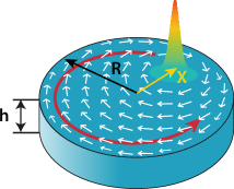
The Thiele equation approach (TEA) is usually used to describe analytically the dynamics of magnetic vortices confined in the free layer of magnetic tunnel junctions (see Fig. 1), as first proposed by HuberHuber (1982) after works on bubble materials by Malozemoff & Slonczewski.Malozemoff and Slonczewski (1979) This theoretical framework allows to predict the vortex core in-plane position by looking at the sum of the forces acting on it. The core is thus seen as a quasi-particle representative of any modification of the global magnetic distribution. At equilibrium, the most general way to express this system Guslienko (2006) is given as
| (1) |
where is an inertial mass term, is the gyrotropic force related to the dominant excitation mode of the vortex at low frequency, is a Gilbert dissipation term, are the restoring forces and represents any additional external forces. For an isolated STVO, these external forces are mainly related to spin-transfer torques.Slonczewski (1996); Li and Zhang (2003)
Any displacement of the vortex core from its original ground state is associated to a modification of the magnetic potential energy . By analogy to simple harmonic motions, one can define a stiffness related to the system. Keeping all generality, this spring-like parameter is not constant but depends on the degree of deformation, i.e., the vortex core position here. Its value allows to calculate the restoring forces appearing in Eq. (1) as
| (2) |
Neglecting magnetocrystalline anisotropy and any external magnetic field, the magnetic potential energy is composed of three terms, namely the exchange , magnetostatic and Zeeman () energies, the latter being thus only associated to the current induced Ampère-Oersted field (AOF). Based on these hypotheses, the total energy can be calculated as Guslienko et al. (2001b); Gaididei et al. (2010)
| (3) |
where is the volume of the magnetic dot, is the normalized magnetization, with the saturation magnetization, is the exchange stiffness coefficient and and are the magnetostatic and AO fields, respectively. This paper is written using cgs units. A conversion table between SI and cgs systems in magnetism is available in ref.Blundell (2001), if necessary.
To proceed to further calculations from Eq. (3), a mathematical description of the magnetization distribution for a vortex state in circular nanopillars of radius is required. In this respect, the so-called two vortex ansatz (TVA), developed by Guslienko et al.,Guslienko and Metlov (2001); Guslienko et al. (2002) has been widely used to study the dynamics of vortices excited by out-of-plane spin-polarized currents.Ivanov and Zaspel (2007); Khvalkovskiy et al. (2009); Belanovsky et al. (2012); Dussaux et al. (2012); Guslienko et al. (2014); Abreu Araujo et al. (2022) This theoretical model relies on the combination of two off-centered rigid vortices with cores located at and , in polar coordinates. Contrary to former descriptions, it presents the advantage of meeting Dirichlet boundary conditions, i.e., no net magnetic charge at the surface edge of the dot. Following TVA, the magnetization at any point in the nanodot can be characterized by a planar angle and core profile angle . Those are expressed as
| (4) |
where is a function describing the vortex core profile. Various propositions of bell-shaped curves have been reported in previous works.Gaididei et al. (2010); Usov and Peschany (1993); Hoellinger et al. (2003) Straightforwardly, one can express the three spatial components of the magnetization using these angles as
| (5) |
Using TVA and Eq. (3), developments have been undertaken in the past two decades to obtain expressions of the stiffness parameters , and , related to each energy component, as a function of the reduced orbit radius .
Gaididei et al.Gaididei et al. (2010) obtained the following expression for the exchange contribution, based on developments from Guslienko et al.,Guslienko et al. (2001a)
| (6) |
where is the exchange length of the material and is the thickness of the free layer. Concerning the magnetostatic term, we recently solvedAbreu Araujo et al. (2022) the expression of the energy proposed by Gaididei et al.,Gaididei et al. (2010) which led to
| (7) |
where , , and are coefficients that can be calculated numerically for each value of the nanodot aspect ratio . Finally, we developed in the same studyAbreu Araujo et al. (2022) an expression for the contribution associated to the AOF, , with being the current density imposed. It is expressed as
| (8) |
In addition to these analytical works, micromagnetic simulations (MMS) have been extensively used to investigate STVO dynamics. Those rely on solving the Landau-Lifshiftz-Gilbert-SlonczewskiLandau and Lifshitz (1935); Gilbert (2004); Slonczewski (1996) equation to predict numerically the properties of magnetic systems of reduced dimensions. Despite the fact that TEA derives from the LLGS formalism, the latter relies on the use of an effective magnetic field rather than spring-like constants. Consequently, there is no direct access to stiffness parameters from micromagnetism. However, as the orbit radius and the energy components are retrievable from most solvers, these parameters can still be calculated by following the procedure described herebelow. As a first step, the energy must be fitted to a chosen expression, as a function of the vortex core position. Then, these functions must be derived according to Eq. (2) to find the corresponding stiffness parameter. This strategy has already been successfully applied in previous studies,Buchanan et al. (2006); Choi et al. (2008); Fried and Metaxas (2016) although for a limited -range.
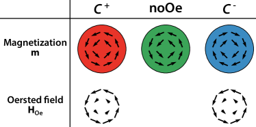
In our case, the GPU-based solver MuMax3 is used to perform micromagnetic simulations.Vansteenkiste et al. (2014) A magnetic tunnel junction presenting a free layer of radius nm and thickness nm is studied. The latter is discretized into cells of dimensions nm3. Typical material parameters for permalloy are used.Cowburn (2000); Vaz et al. (2008); Guimarães and Guimaraes (2009) The saturation magnetization and exchange stiffness coefficient are emu/cm3 and erg/cm, respectively. The Gilbert damping constant is fixed at 0.01 and the spin-current polarization at 0.2. A polarizer presenting a perpendicular direction of magnetization is used. MuMax3 includes both SlonczewskiSlonczewski (1996) and Zhang-LiZhang and Li (2004) spin-transfer torques. Nonetheless, given the out-of-plane current configuration, the field-like torque has a limited influence on the dynamics as the vortex profile is uniform along the free layer thickness for thin magnetic dots.Guslienko (2022) In light of these considerations, we have chosen to simplify the analysis by assuming an adiabatic situation, where the degree of non-adiabaticity is fixed at zero. The vortex polarity is chosen to be . The influence of the temperature is not taken into account in this study. Current densities of and A/cm2 are imposed into the oscillator, in the positive -direction which allows to respect one of the two necessary conditions for steady-state precessionsAbreu Araujo et al. (2022) (i.e., ). The second criterion is to inject a current exceeding the first critical current density . When , simulations are initiated with a vortex core translated to which damps back to the center of the dot, i.e., . For however, two simulations are required to explore the whole range of for a given current, as the steady-state orbit is different from zero. Each time, a first simulation is started at and a second one at . Both are stopped when steady-state is reached. It should be noted that the vortex is not at equilibrium at the start of the simulations, and that the data acquisition takes place while the vortex core relaxes towards its steady-state position, determined by the value of the imposed current. This allows to capture the stiffness over the entire -range, for any . In addition, three different situations are investigated (see Fig. 2), depending on the relative orientation between the in-plane curling magnetization and the AOF. A first set of simulations is performed without considering , then a set with parallel to the curling magnetization, i.e., , and finally a set with antiparallel to the curling magnetization, i.e., . Those are labelled below in this manuscript as noOe, and , respectively. To evaluate the Ampère-Oersted field, we consider an idealized situation where the current density is uniform in the pillar. Furthermore, as the thickness of the free layer is considerably smaller than the overall thickness of the pillar, edge effects are neglected, i.e., an infinite cylinder is assumed (as in ref.Abreu Araujo et al. (2022)). The vortex core position as well as the energy components , and are internally computed by MuMax3 between each timestep.
The arbitrarily chosen functions for fitting the energy components are even power polynomials of the 10 order, preceded by a pre-factor that depends on material and geometrical parameters. They have the following form
| (9) | ||||
| (10) | ||||
| (11) |
where , and are the coefficients to be fitted relative to each term of the polynomials. Nonlinear least square fits are performed for , the upper value being close to the limit of vortex stability.Abreu Araujo et al. (2022) Using an adapted version of Eq. (2), i.e., , one can easily derive the expressions of the spring-like stiffness parameters, given as
| (12) | ||||
| (13) | ||||
| (14) |
Let us add that a pretreatment is used before fitting. It consists in denoising the raw micromagnetic results thanks to a wavelet transform technique.Lee et al. (2019) This allows to obtain more accurate fitting parameters by getting rid of MuMax3 internal computational uncertainties. For every fit, we obtained a relative standard error on the intercept (see Eqs. (9)-(11)) of . For the quadratic coefficient (resp. biquadratic ), it is always below (resp. , while being below for most fits). Concerning the higher order coefficients , and , the errors were often a bit more important, which can be easily understood. Indeed as by definition, these terms contribute only to a limited extent to the total energy value.
III Results & Discussion
Micromagnetic results (see Eqs. (12)-(14)) are compared to the analytical expressions presented previously (see Eqs. (6)-(8)). The evolution of the restoring parameters , and with respect to the vortex core position is depicted on Figs. 3, 4 & 5, respectively. Let us start with general observations valid for the three energy components. A slight disagreement is noticed between micromagnetism and TEA, even when the vortex core is at the center of the nanodot. These discrepancies could originate from two main hypotheses performed during TEA calculations. Firstly, the out-of-plane magnetization component is neglected for each derivation,Gaididei et al. (2010); Abreu Araujo et al. (2022) due to the small area occupied by the vortex core. This simplification, necessary to obtain fully analytical expressions, is applicable as a preliminary approximation. However, even if the vortex core profile contribution is small, it is still different from zero. This is especially true for nanopillars of reduced radius, where the vortex core occupies a significant surface inside the free layer. Secondly, the magnetization is considered constant along the dot thickness. While appropriate for nanodots presenting a thickness of the order of the exchange length,Metlov and Guslienko (2002); Guslienko et al. (2008); Guslienko (2006) this assumption is not perfectly verified in micromagnetic simulations. In addition, supplementary deviations arise for an off-centered moving vortex core, explaining partly the TEA imperfect modeling when is evolving. Indeed within TVA, the vortex core is simply translated to a greater orbit while keeping its original shape. Such rigid motion assumption is justified by the fact that this ansatz was originally designed to study small displacements of static vortex cores. However, various groupsKhvalkovskiy et al. (2009); Fried and Metaxas (2016); Buchanan et al. (2006) have already shown the limitations of such theoretical framework to model accurately dynamic vortices. It has also been shown that a vortex core approaching the dot edge sees a growing trail of opposite magnetization appearing next to it.Kasai et al. (2006); Gaididei et al. (2010); Guslienko et al. (2008) Such dip, later responsible for the nucleation of a vortex of reversed polarity,Hertel et al. (2007) induces energy changesGliga et al. (2011) not perceived within TEA.
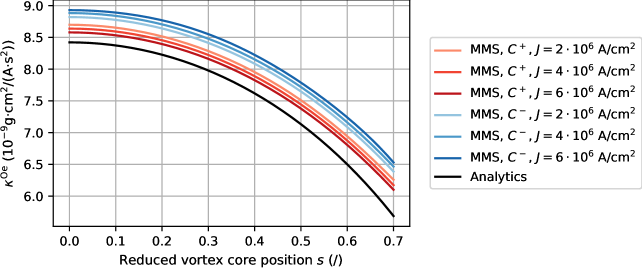
Furthermore, a current induced splitting of the stiffness parameters can be observed, as already reported by Choi et al.. Choi et al. (2008) For increasing currents, the and curves move further apart from the noOe case. This behavior is not predicted at all by TEA calculations. These findings result from a modification of the spin distribution caused by the AOF. Spins are tilted under its influence, leading them to deviate from the theoretical TVA magnetization. These effects will be discussed later in the manuscript. This distortion increases near the dot edges, considering the linear dependence of the AOF amplitude on the radial coordinate within the free layer. Moreover, the splitting increases with the current density as the AOF amplitude is proportional to the latter. This conclusion is supported by the fact that, in the noOe configuration, the stiffness is independent from the current value. Indeed, the mean difference in the simulations at and A/cm2 compared with those at A/cm2 is less than 0.17% for the exchange stiffness, and less than 0.06% for the magnetostatic stiffness (see green curves on Figs. 3 & 4). A final point of interest is to note that for the exchange contribution, the favored configuration (i.e., ) results in a stiffer force parameter, while the opposite is noticed for the other terms. As for now, we lack a robust justification for this phenomenon and further investigations would be required. After these preliminary observations, let us now look at each of the confinement contributions in more detail.
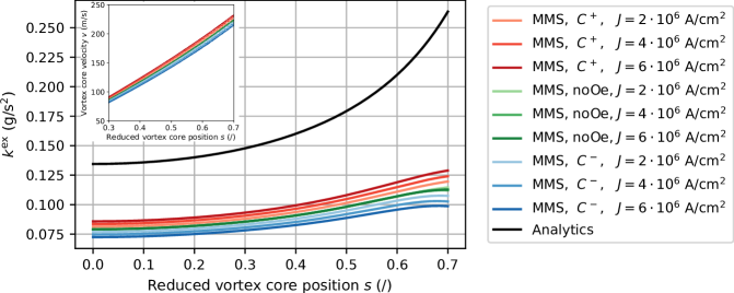
The TEA exchange stiffness parameter is the term presenting the most imprecise description compared to the simulated behavior (see Fig. 3). For each , the analytical value overestimates all MMS results. The predicted evolution is satisfying for a slightly off-centered vortex but divergesGuslienko et al. (2001a); Gaididei et al. (2010) to infinity for , as expected from Eq. (6) and the disregard of the vortex core profile in the analytical derivation. This does not reflect the behavior extracted from simulations as a maximum seems to appear at (at least for and noOe), followed by a decrease of the value. Various reasons could explain this drop. The most probable ones would be the interaction of the core with the dot edge and the 6-neighbor small angle approximation used by micromagnetic solvers, preventing accurate computation for large excitations. Moreover, a very large impact of the AOF is noticed. For a centered vortex core and A/cm2, the exchange stiffness in configuration is 18% larger than the curve of opposite chirality. This value grows up to 31% at . Such considerable influence is linked to the fact that the gradient of magnetization appears in the exchange energy formula, as shown in Eq. (3). Any slight deviation in spin directions appearing in simulations with AOF has thus a major impact on the stiffness results compared to calculations using the unaffected theoretical distribution. Besides, the rotational velocity of the vortex core can give an indication of its degree of deformation (see inset in Fig. 3), especially when compared with the critical velocity where is the gyromagnetic ratio.Lee et al. (2008) The velocities reached at the largest oscillation orbits are gradually approaching m/s, suggesting a large dip following the vortex core. An impact of the chirality on the velocity was to be expected, given the frequency splitting reported in ref.Abreu Araujo et al. (2022). However, the impact of the current magnitude on the velocity, for the same chirality and vortex core position, shows its influence on the magnetization dynamics.
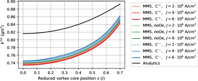
In Figure 4, one can observe that, as expected, the magnetostatic confinement dominates largely both other terms,Guslienko et al. (2006); Guslienko (2006) at least for the range of currents explored. For dots with wider radii, or at very large current densities, the AOF stiffness parameter should gain relative importance. The analytical expression of overestimates the value extracted from simulations (for the noOe case) by 10% at . This result is consistent with the overestimation of the first critical current and eigenfrequency observed in our previous studyAbreu Araujo et al. (2022) when using TEA, as and . As depicted in Fig. 4, the magnetostatic confinement constantly increases as the core moves towards the edge, for both methods. Though the growth is limited, as is only 15% greater at compared to the centered vortex case (for noOe). The analytical function models well the simulated evolution of with respect to for low vortex displacements. For greater values however, discrepancies are observed between the two methods. This difference is partially explained by the difficulty to obtain an analytical expression for the stray field.Gaididei et al. (2010) The AOF seems to have a limited impact on the magnetostatic energy, all curves being close to the noOe configuration.
Furthermore, the analytical expression of underestimates simulation results (see Fig. 5), for both and . However the predicted behavior describes finely its evolution on the whole range. Such accuracy was bound to occur given the easier derivation of the Zeeman energy,Abreu Araujo et al. (2022) compared to non-local magnetostatic interactions. It may also be due to the higher order polynomial used in Eq. (8). More fundamentally, the AOF does not present any out-of-plane component as it appears in a plane perpendicular to the current direction, if edge effects are neglected.Abreu Araujo et al. (2022) Following Eq. (3), the out-of-plane vortex magnetization has thus a negligible impact on the Zeeman energy. Nevertheless, constantly decreasing curves are obtained, being 40% greater for a centered vortex than in . In addition, a non-negligible impact of the AOF is again perceived on its own stiffness parameters , in the simulations. This result was expected, as we get a modification of the magnetization distribution appearing in Eq. (3). The splitting stays roughly constant in amplitude, irrespective of the vortex core position.
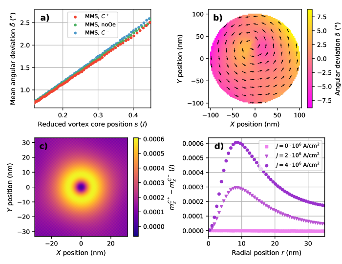
Finally, let us look at the magnetic texture and the influence of the AOF on it. In Figure 6a we define the mean angular deviation as , where is the angle between the planar magnetization vector predicted by the TVA (see Eqs. (4) & (5)) and the one retrieved from simulations, for a given micromagnetic cell, and is the total number of cells. The effects of the core deformation will be discussed afterwards. The mean deviation is close to zero for low values and increases the further the vortex core is located from the center, as expected given that the TVA was designed for statics. What is more useful here is to use the TVA as a reference to compare the three configurations we are examining. As already suggested by the inset in Figure 3, one can see that the deformation of the magnetic texture depends on the relative orientation between the in-plane swirling spins and the AOF. In addition, the splitting of the angular deviation widens as the core approaches the edge of the magnetic disc. To better understand these results, an out-of-plane snapshot of the angular deviation for each cell of the disc during a simulation is available in Figure 6b. As anticipated, the regions that deviate most from the TVA predictions are those close to the core (i.e., the dip) and at the edges of the disc. As the core moves towards the center, the deviations gradually become smaller.
In Figure 6c, one can observe the deformation of the core profile for a centered vortex. To do so, we compare the out-of-plane magnetization components of two free layers under the same current but containing vortices of opposite chiralities. A more stringent cell size of nm3 was used for a finer precision. As , we plot to highlight any variation in the planar magnetization components. At exactly , there is no difference between both situations as the amplitude of the AOF is zero at these coordinates. In every other points of the vortex core though, the magnetization is confined in the plane by the AOF, modifying the value of and . By conservation of the norm, the value of changes by an amount that depends on the relative orientation between the planar magnetization and the magnetic field. Such effect is comparable to what was reported by Dussaux et al.Dussaux et al. (2012) for a perpendicular magnetic field, i.e., (with the saturation field), where part of the magnetization was imposed outside the vortex core by the addition of an external field. In our case however, little effect is visible outside of the vortex core. In fact, as the magnetization is planar for both chiralities in this region, (which is nearly zero) is not impacted by the confinement. For reference, the half width at half maximum of the vortex core profile is nm. In Figure 6d, one can see that the maximum deformation depends linearly on the amplitude of the current. This effect is a direct evidence of the influence of , and therefore of the AOF, on the magnetic texture. The choice of working at was made to ensure that the core is at exactly the same location regardless of the chirality, even if the deformation is fairly small at this position. One last important thing to note is that part of this distortion originates from the spin-transfer torque. However, the further the core is from the center, the greater the relative contribution of the field to the deformation, as its amplitude increases with the position. It should be added that the value of the energy at is of little importance for the stiffness parameters, since those are rather linked to the shape of the potential well.
To put the results presented in this work into perspective, we believe that our restoring parameter expressions could be integrated into existing TEA models, to replace analytical expressions. Following such a data-driven approach, i.e., deriving , and from a limited set of micromagnetic simulations, one could obtain more reliable results from TEA compared to micromagnetism and, by extension, to experimental results. The downside being that these parameters would only be valid for a given geometry and material parameters. Moreover, to obtain expressions valid for a continuous range of currents, one should proceed to an interpolation between a few curves selected cleverly, as the splitting increases with . Nevertheless, this constitutes an alternative solution for a more accurate analytical model describing STVO dynamics.
Although the influence of the temperature was not taken into account in this study, one may still discuss its potential effect on the restoring forces. It is well known that a magnetic tunnel junction powered by large current densities sees its temperature rise,Prejbeanu et al. (2004, 2013); Strelkov et al. (2018) by up to several tens of degrees.Lee and Lim (2008) This Joule heating is especially important near the tunnel barrier (typically made of MgO) as its resistance is orders of magnitude higher than the one of the metallic layers. More importantly, the temperature reached depends on the magnitude of the current.Lee and Lim (2008) This means that the splitting phenomenon of the restoring forces, only caused by the current induced Ampère-Oersted field in the present study (as K), could be enhanced by the larger temperature increase for higher currents. Indeed, any local random fluctuation of the spin texture due to thermal effects impacts directly the value of the energy components, following Eq. (3). It is clear that these effects, as well as the impact of the temperature on the different material parameters, could be considered in future works to further improve the validity of TEA-based models.
IV Conclusion
Restoring forces appearing in off-centered magnetic vortex states were examined theoretically. Exchange, magnetostatic and Zeeman stiffness parameters were obtained from simulations and compared to analytical expressions from the literature. To do so, the energy components were directly extracted from MuMax3, then fitted to high-order polynomials. The derivatives of these functions allowed to calculate stiffness parameters, analogously to what is done for classical springs under deformation. Discrepancies between the Thiele equation approach results and micromagnetic simulations were observed for each term, such as shifts of the curves and disagreeing behavior for large relative core position value. These differences were expected given the assumptions used for the theoretical derivations. More importantly, a chirality dependent splitting was observed in the stiffness value, with a deviation depending on the input current intensity. We provide evidence that this phenomenon is the result of a modification of the spin distribution caused by the current induced Ampère-Oersted field. This hypothesis is supported by the fact that the stiffness was independent of the current imposed when the AOF was not taken into account. Finally, we believe that the expressions we derived from simulations could be implemented into existing STVO models to better render experimental results.
Acknowledgements
Computational resources have been provided by the Consortium des Équipements de Calcul Intensif (CÉCI), funded by the Fonds de la Recherche Scientifique de Belgique (F.R.S.-FNRS) under Grant No. 2.5020.11 and by the Walloon Region. F.A.A. is a Research Associate and S.d.W. is a FRIA grantee, both of the F.R.S.-FNRS.
References
- Metlov and Guslienko (2002) K. L. Metlov and K. Y. Guslienko, Journal of Magnetism and Magnetic Materials 242, 1015 (2002).
- Guslienko (2006) K. Y. Guslienko, Applied Physics Letters 89, 022510 (2006).
- Hertel et al. (2007) R. Hertel, S. Gliga, M. Fähnle, and C. Schneider, Physical Review Letters 98, 117201 (2007).
- Guslienko (2008) K. Y. Guslienko, Journal of Nanoscience and Nanotechnology 8, 2745 (2008).
- Hrkac et al. (2015) G. Hrkac, P. S. Keatley, M. T. Bryan, and K. Butler, Journal of Physics D: Applied Physics 48, 453001 (2015).
- Katine et al. (2000) J. Katine, F. Albert, R. Buhrman, E. Myers, and D. Ralph, Physical Review Letters 84, 3149 (2000).
- Kiselev et al. (2003) S. I. Kiselev, J. Sankey, I. Krivorotov, N. Emley, R. Schoelkopf, R. Buhrman, and D. Ralph, Nature 425, 380 (2003).
- Slavin and Tiberkevich (2009) A. Slavin and V. Tiberkevich, IEEE Transactions on Magnetics 45, 1875 (2009).
- Zeng et al. (2013) Z. Zeng, G. Finocchio, and H. Jiang, Nanoscale 5, 2219 (2013).
- Pribiag et al. (2007) V. Pribiag, I. Krivorotov, G. Fuchs, P. Braganca, O. Ozatay, J. Sankey, D. Ralph, and R. Buhrman, Nature Physics 3, 498 (2007).
- Sluka et al. (2015) V. Sluka, A. Kákay, A. Deac, D. Bürgler, C. Schneider, and R. Hertel, Nature Communications 6, 1 (2015).
- Abreu Araujo et al. (2022) F. Abreu Araujo, C. Chopin, and S. de Wergifosse, Scientific Reports 12, 10605 (2022).
- Yamada et al. (2007) K. Yamada, S. Kasai, Y. Nakatani, K. Kobayashi, H. Kohno, A. Thiaville, and T. Ono, Nature Materials 6, 270 (2007).
- Guslienko et al. (2008) K. Y. Guslienko, K.-S. Lee, and S.-K. Kim, Physical Review Letters 100, 027203 (2008).
- Khvalkovskiy et al. (2009) A. Khvalkovskiy, J. Grollier, A. Dussaux, K. A. Zvezdin, and V. Cros, Physical Review B 80, 140401 (2009).
- Gaididei et al. (2010) Y. Gaididei, V. P. Kravchuk, and D. D. Sheka, International Journal of Quantum Chemistry 110, 83 (2010).
- Jenkins et al. (2016) A. Jenkins, R. Lebrun, E. Grimaldi, S. Tsunegi, P. Bortolotti, H. Kubota, K. Yakushiji, A. Fukushima, G. de Loubens, O. Klein, et al., Nature Nanotechnology 11, 360 (2016).
- Wittrock et al. (2021) S. Wittrock, P. Talatchian, M. Romera, S. Menshawy, M. Jotta Garcia, M.-C. Cyrille, R. Ferreira, R. Lebrun, P. Bortolotti, U. Ebels, et al., Applied Physics Letters 118, 012404 (2021).
- Torrejon et al. (2017) J. Torrejon, M. Riou, F. Abreu Araujo, S. Tsunegi, G. Khalsa, D. Querlioz, P. Bortolotti, V. Cros, K. Yakushiji, A. Fukushima, et al., Nature 547, 428 (2017).
- Romera et al. (2018) M. Romera, P. Talatchian, S. Tsunegi, F. Abreu Araujo, V. Cros, P. Bortolotti, J. Trastoy, K. Yakushiji, A. Fukushima, H. Kubota, S. Yuasa, M. Ernoult, D. Vodenicarevic, T. Hirtzlin, N. Locatelli, D. Querlioz, and J. Grollier, Nature 563, 230 (2018).
- Thiele (1973) A. Thiele, Physical Review Letters 30, 230 (1973).
- Thiele (1974) A. Thiele, Journal of Applied Physics 45, 377 (1974).
- Guslienko et al. (2001a) K. Y. Guslienko, V. Novosad, Y. Otani, H. Shima, and K. Fukamichi, Applied Physics Letters 78, 3848 (2001a).
- Buchanan et al. (2006) K. S. Buchanan, P. E. Roy, M. Grimsditch, F. Y. Fradin, K. Y. Guslienko, S. D. Bader, and V. Novosad, Physical Review B 74, 064404 (2006).
- Choi et al. (2008) Y.-S. Choi, S.-K. Kim, K.-S. Lee, and Y.-S. Yu, Applied Physics Letters 93, 182508 (2008).
- Fried and Metaxas (2016) J. P. Fried and P. J. Metaxas, Physical Review B 93, 064422 (2016).
- Huber (1982) D. Huber, Physical Review B 26, 3758 (1982).
- Malozemoff and Slonczewski (1979) A. Malozemoff and J. C. Slonczewski, Magnetic domain walls in bubble materials: advances in materials and device research, Vol. 1 (Academic press, 1979).
- Slonczewski (1996) J. C. Slonczewski, Journal of Magnetism and Magnetic Materials 159, L1 (1996).
- Li and Zhang (2003) Z. Li and S. Zhang, Physical Review B 68, 024404 (2003).
- Guslienko et al. (2001b) K. Y. Guslienko, V. Novosad, Y. Otani, H. Shima, and K. Fukamichi, Physical Review B 65, 024414 (2001b).
- Blundell (2001) S. Blundell, Magnetism in condensed matter (OUP Oxford, 2001).
- Guslienko and Metlov (2001) K. Y. Guslienko and K. L. Metlov, Physical Review B 63, 100403 (2001).
- Guslienko et al. (2002) K. Y. Guslienko, B. Ivanov, V. Novosad, Y. Otani, H. Shima, and K. Fukamichi, Journal of Applied Physics 91, 8037 (2002).
- Ivanov and Zaspel (2007) B. Ivanov and C. Zaspel, Physical Review Letters 99, 247208 (2007).
- Belanovsky et al. (2012) A. D. Belanovsky, N. Locatelli, P. Skirdkov, F. Abreu Araujo, J. Grollier, K. A. Zvezdin, V. Cros, and A. K. Zvezdin, Physical Review B 85, 100409 (2012).
- Dussaux et al. (2012) A. Dussaux, A. Khvalkovskiy, P. Bortolotti, J. Grollier, V. Cros, and A. Fert, Physical Review B 86, 014402 (2012).
- Guslienko et al. (2014) K. Y. Guslienko, O. V. Sukhostavets, and D. V. Berkov, Nanoscale Research Letters 9, 1 (2014).
- Usov and Peschany (1993) N. Usov and S. Peschany, Journal of Magnetism and Magnetic Materials 118, L290 (1993).
- Hoellinger et al. (2003) R. Hoellinger, A. Killinger, and U. Krey, Journal of Magnetism and Magnetic Materials 261, 178 (2003).
- Landau and Lifshitz (1935) L. Landau and E. Lifshitz, Physikalische Zeitschrift der Sowjetunion 8, 153 (1935).
- Gilbert (2004) T. L. Gilbert, IEEE Transactions on Magnetics 40, 3443 (2004).
- Vansteenkiste et al. (2014) A. Vansteenkiste, J. Leliaert, M. Dvornik, M. Helsen, F. Garcia-Sanchez, and B. Van Waeyenberge, AIP Advances 4, 107133 (2014).
- Cowburn (2000) R. Cowburn, Journal of Physics D: Applied Physics 33, R1 (2000).
- Vaz et al. (2008) C. Vaz, J. Bland, and G. Lauhoff, Reports on Progress in Physics 71, 056501 (2008).
- Guimarães and Guimaraes (2009) A. P. Guimarães and A. P. Guimaraes, Principles of nanomagnetism, Vol. 7 (Springer, 2009).
- Zhang and Li (2004) S. Zhang and Z. Li, Physical review letters 93, 127204 (2004).
- Guslienko (2022) K. Guslienko, Magnetism 2, 239 (2022).
- Lee et al. (2019) G. Lee, R. Gommers, F. Waselewski, K. Wohlfahrt, and A. O’Leary, Journal of Open Source Software 4, 1237 (2019).
- Kasai et al. (2006) S. Kasai, Y. Nakatani, K. Kobayashi, H. Kohno, and T. Ono, Physical Review Letters 97, 107204 (2006).
- Gliga et al. (2011) S. Gliga, Y. Liu, and R. Hertel, in Journal of Physics: Conference Series, Vol. 303 (IOP Publishing, 2011) p. 012005.
- Lee et al. (2008) K.-S. Lee, S.-K. Kim, Y.-S. Yu, Y.-S. Choi, K. Y. Guslienko, H. Jung, and P. Fischer, Physical Review Letters 101, 267206 (2008).
- Guslienko et al. (2006) K. Y. Guslienko, X. Han, D. Keavney, R. Divan, and S. Bader, Physical Review Letters 96, 067205 (2006).
- Prejbeanu et al. (2004) I. Prejbeanu, W. Kula, K. Ounadjela, R. Sousa, O. Redon, B. Dieny, and J.-P. Nozieres, IEEE Transactions on Magnetics 40, 2625 (2004).
- Prejbeanu et al. (2013) I. L. Prejbeanu, S. Bandiera, J. Alvarez-Hérault, R. C. Sousa, B. Dieny, and J.-P. Nozières, Journal of Physics D: Applied Physics 46, 074002 (2013).
- Strelkov et al. (2018) N. Strelkov, A. Chavent, A. Timopheev, R. Sousa, I. Prejbeanu, L. Buda-Prejbeanu, and B. Dieny, Physical Review B 98, 214410 (2018).
- Lee and Lim (2008) D. Lee and S. H. Lim, Applied Physics Letters 92, 233502 (2008).