beam-align: distributed user association for mmWave networks with multi-connectivity
Abstract
Since spectrum below 6 GHz bands does not suffice to meet the high bandwidth requirements of 5G use cases, 5G networks expand their operation to mmWave bands with multi-GHz of available spectrum. However, operation at mmWave bands raises two challenges: high penetration loss and susceptibility to objects blocking the line-of-sight. As a remedy, transmitters point their antennas to their receivers using beamforming to contain the signal in the direction of the intended receiver. To avoid loss of connectivity due to blockers or other factors such as rain, users can be connected to multiple base stations (BS). While these two features, beamforming and multi-connectivity, can mitigate the challenges of mmWave bands, it is not trivial to find the optimal user association which can maintain the minimum rate requirements of the users. In this paper, we first formulate a throughput-maximizing user association scheme considering beamforming and multi-connectivity, and investigate the behavior of the optimal scheme to devise a simple, yet efficient heuristic that does not require global network information. Our proposal, dubbed beam-align, which only uses local information at a BS, performs close to the optimal in terms of per-user capacity and user satisfaction levels and has only polynomial complexity. Our numerical analysis shows that beam-align outperforms the frequently-used association schemes based on SNR. To investigate the performance of beam-align also under various challenging settings, we consider three scenarios: presence of blockers, different levels of rain intensity, and presence of clustered users. From simulations, we observe that beam-align is robust against different conditions, as it maintains a stable performance under the studied scenarios.
Index Terms:
User association, beamforming, resilience, mmWave bands, cellular networks, 5G.I Introduction
5G networks can use frequency bands above 6 GHz known as mmWave bands to meet the high rate requirements of data-intensive use cases such as immersive media applications [29]. However, these high frequency bands have increased path losses compared to sub-6GHz channels and are more susceptible to channel impairments, e.g., due to blocking objects or rain drops [21]. Massive directional antennas in mmWave base stations (BSs) can compensate for this increased path loss, by transmitting in focused beams via beamforming. Beamforming increases the channel gain based on the alignment of the beams of a BS and a user [23]. Alignment then becomes a key factor in determining the link quality. Additionally, to compensate for blockage or other channel impairments such as rain, users can increase their connection reliability by simultaneously connecting to multiple BSs as illustrated in Fig.1. While multi-connectivity (MC) can be implemented in different ways, e.g., packet duplication or packet splitting [33], we investigate a scenario with packet-splitting MC, in which a user’s downlink traffic is split over different links to also increase the total user throughput.
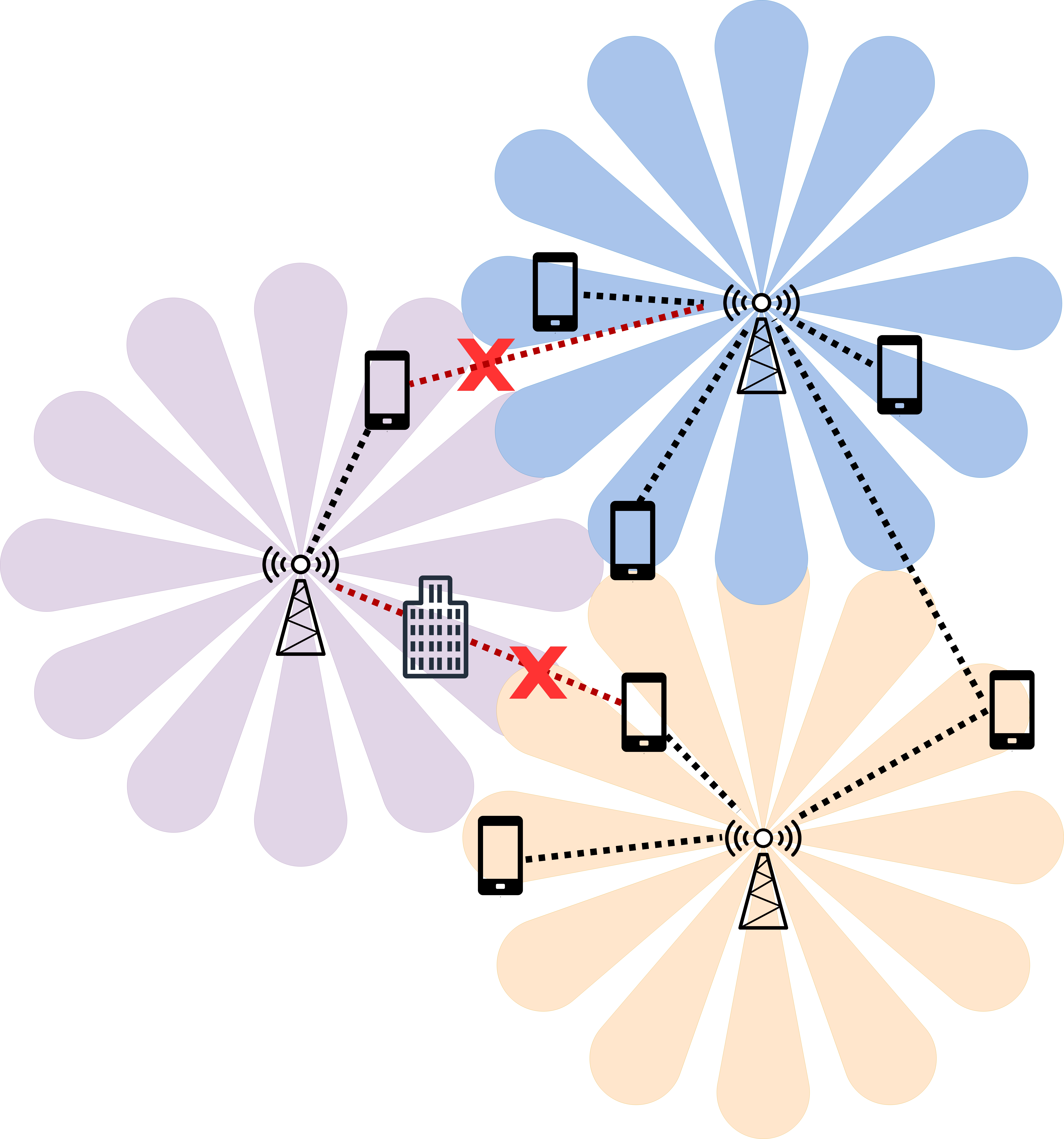
With beamforming and MC, 5G networks can unlock the potential of mmWave bands and serve their users with high data rates. However, two questions arise in this context: (i) how many connections should each user maintain to attain the minimum data rate asserted by its application? and (ii) to which BSs should each user connect? Prior research on MC shows the increased throughput or reliability offered to a single user [10]. But, studies such as [38] conclude that if MC is applied to all users, the number of connections per user should be dynamically determined rather than a simple -MC scheme in which each user connects to BSs. Under a -MC scheme, per-user capacity decreases while network can attain higher reliability in terms of a reduced outage probability in comparison to single connectivity (SC) settings. But, finding the optimal degree of MC for each user requires solving an optimization problem considering all users’ rate requirements and channel states. However, acquiring this information is challenging and impractical, making optimal schemes prohibitively complex.
Based on the aforementioned challenges and state-of-the-art, our goal is to design a user-association (UA) scheme that maximizes network throughput while meeting the users’ minimum rate requirements by exploiting a dynamic form of MC. We will address the following research questions in this paper:
-
•
What is the optimal number of connections in a mmWave network for a user with a certain downlink rate requirement? How does this optimal number of connections depend on the network load?
-
•
How does the transmission beamwidth of a BS (e.g., smaller or larger) affect the optimal number of connections per user and the network performance?
-
•
Can we design a near-optimal distributed UA scheme that is only based on local user information?
-
•
How do realistic scenarios such as blockage, rain and user clustering affect the performance of UA schemes in terms of per-user throughput and user satisfaction level?
While addressing these questions, we have the following key contributions in this paper:
-
•
We propose an optimal UA scheme based on maximizing a utility function of the throughput, which takes into account key properties of mmWave, such as beamforming and increased path loss. We show that in the optimal UA scheme, most users have MC when the network load is low. Moreover, our analysis of this optimal UA scheme shows that the decision to connect to a certain BS is mainly based on the antenna alignment between the BS and the user.
-
•
Based on our observation that users connect to the BSs which have small misalignment with the user’s receive antenna, we devise beam-align in which users are associated to BSs based on the alignment of the beams. beam-align offers benefits in terms of per-user throughput and satisfaction level close to optimal, while having only polynomial time complexity in the number of users and requiring only the knowledge of antenna orientation of a user.
-
•
We analyse the robustness of beam-align as well as SNR-based association schemes in the literature under various scenarios: namely, when i) there are blockers; ii) different levels of rain that impair the mmWave links; and iii) the users are clustered.
In the following sections, we first overview the most relevant work in the areas of multi-connectivity, mmWave and user association (Section II). Next, we elaborate on the scenario and models we use in this paper (Section III) and propose an optimization model for UA, based on maximizing the total throughput (Section IV). Then, we analyse the outcomes of the optimal UA scheme and propose the UA scheme beam-align (Section V), which we compare to the optimal scheme. In Section VII, we investigate the robustness of both UA schemes. Finally, we discuss the limitations of our work and some future research directions in Sections VIII and IX.
II Related work
In this section, we describe related work on UA in a mmWave setting. We focus on four areas: SC user association, MC user association, beamforming and simple heuristics for UA. For a complete overview of 5G user association, we refer to [21] and [5].
SC user association
Optimal UA under SC for mmWave networks is widely studied in the literature [8]. Existing studies design new algorithms for UA, for example by using a Markov decision process [22] to minimize the number of handover decisions and to maximize the throughput. However, a key shortcoming of these works is that they do not take the directionality of the beams into account, while this could greatly influence the user association. In [17], users decide to connect to a BS based on the directional signals in an area with a high building density, as buildings can reflect signals in different directions. In this line of research, the optimization criterion is typically total network throughput. Other objectives that have been investigated are energy efficiency [25] or outage probability [39]. Another study that is worth mentioning is [31], in which the authors formulate and solve an optimization problem based on maximizing throughput for different beamwidths. All UA schemes that are described above can be extended to a fixed MC UA scheme. However, extending them to dynamic MC scheme is not straightforward or might incur high complexity.
MC user association
Existing studies on MC typically consider a fixed MC scheme as in [18, 19, 20]. Generally speaking, primary objective in these studies is to maximize the total throughput [34, 19, 20, 24] while some studies aim at maximizing energy efficiency [26], minimizing the number of resources in the system [35], or the outage probability [32]. The closest study to ours is [34] and [27]. Tatino et al. [34] consider a scenario with MC and find a near-optimal UA scheme based on column generation, which shows that MC can drastically increase throughput and reliability. Contrary to [34], we take beamforming into account as this is a key property of mmWave. Petrov et al. [27] provide a framework based on queuing theory for mmWave scenarios, including MC and beamforming and focus on small scenarios with a high building density. Again, they show that MC increases the throughput and reliability. Sopin et al. [32] investigate different user association schemes in joint terahertz and mmWave networks with beamforming and MC. However, this study focuses on minimizing the outage probability due to blockages and mobility of users, while our focus in on optimizing the throughput and satisfaction of the users.
Beamforming
Directional beams in mmWave channels help overcome high path loss. Several studies investigate how to steer, manage and align these beams to achieve the highest throughput or best efficiency [2, 16, 37]. These works all show that the smaller the beam, the better the throughput. However, smaller and more beams may also cause more overhead and complexity, as all these beams have to be managed. As these directional beams also cause different gain patterns around a BS, UA becomes a difficult problem which can be solved in different ways. In [3, 31], the mmWave UA problem is formulated as a matching and auction game, respectively, and in [18, 35] the authors use machine learning to solve the UA problem. Due to the complexity of the problem, most of these models focus on a small setting, while mmWave is used for scenarios with high user density. Moreover, most of these works are based on single connectivity, as multi-connectivity only brings more complexity and overhead. Our work differs from earlier works as we consider a more complete mmWave setting with beamforming and MC.
UA heuristics
Several learning-based UA heuristics are proposed in [35] which do not assume perfect channel knowledge. Authors compare their proposals to two baseline (distributed) heuristics: connecting to all available BSs and connecting to as many BSs as necessary to satisfy the users’ quality of service constraints. Another study is [12] which compares four simple distributed UA policies in a setting where users join and leave the network. They show that UA should be based on highest throughput. However, MC and beamforming are not taken into account. Three heuristics for UA are studied in [22]: (1) connect to the least-loaded BS, (2) connect to the highest instantaneous rate, and (3) connect to the highest SNR. In this work, the authors showed that out of these three heuristics, the SNR-based approach performed best in terms of spectral efficiency. However, some of these UA schemes need knowledge of the entire network. Contrary to most of these works that only verify their results on very small instances, we aim to design a UA scheme that is scalable and performs well also in larger settings.
III System model
We consider a cellular network consisting a set of BSs operating at mmWave bands which are expected to serve a set of users . If there is a link between user and BS , we refer to this link as link . Each user has a downlink rate requirement to have an acceptable service quality.
III-A Antenna model
We use a directional beamforming channel model as given in [6], where and are defined as the beamwidth of a user and a BS, respectively. Moreover, is the boresight and the geographical angle of link as illustrated in Fig. 2. We assume that BSs and users have a sectorized linear antenna [4, 11], which means that the beams are placed uniformly around the BS and user (Fig. 2). This results in the boresight angles , where is the set of all beam directions. We refer to and as the set of user and BS beam directions, with beamwidths and , respectively. Moreover, we assume that every BS beam can be occupied by at most users. The BS will then serve these users in the same beam in a time-sharing manner.
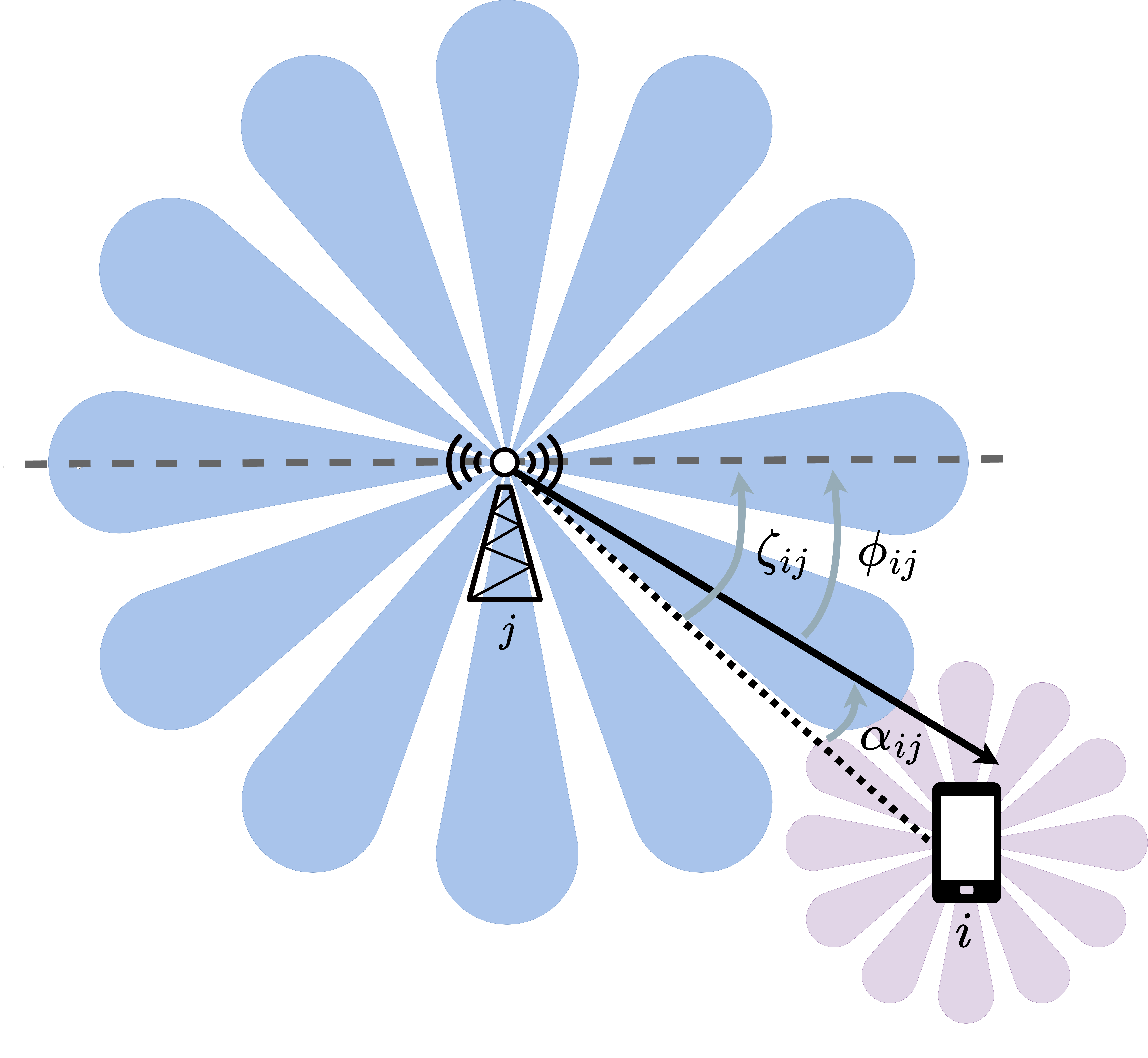
The antenna gain is denoted by for the transmitter of the link and by for the receiver of this link. Following the mmWave-based IEEE 802.15.3c standard [36], this gain in dB is defined as follows:
| (1) |
where is the misalignment between the beam (boresight angle) and the geographical angle of link in degrees, and is the 3 dB beamwidth.
III-B Channel model
We use the 3GPP path loss model [1] for mmWave networks which depends on the 3D distance between user and BS , denoted by . Since mmWave links are easily blocked by buildings, trees or people, we distinguish links that are in line-of-sight (los) and in non-line-of-sight (nlos). The path loss in dB is:
| (2) | ||||
| (3) |
Here, is the centre frequency in GHz, and and are standard normally distributed random variables with standard deviation and dB, respectively. To calculate the 3D distance, we assume the height difference between a user and a BS is m [1]. In the optimization model that is introduced in Section IV, we assume every path is in line-of-sight. However, in Section VII, we consider also non-line-of-sight due to the blockers in the environment.
III-C SNR and channel capacity
We assume that each BS transmits with equal power and divides this power among its beams. Moreover, each BS operates over a channel with a bandwidth of Hz. We denote by the set of BSs that user is connected to. When users have multiple links, we assume that the traffic is split over all links, which means that the total capacity per user is the sum over all link capacities (packet splitting, [33]). To account for the overhead that is caused by load balancing and beam management [2], the actual perceived capacity will be a fraction of the total link capacity.
To compute the channel capacity, let us first calculate the signal-to-noise ratio for link as follows:
| (4) |
in which the noise is calculated as the thermal noise plus a noise factor . We assume that a link must maintain a minimum SNR level to ensure decodability of the received signal.
Consequently, the Shannon’s channel capacity for user denoted by can be defined as follows:
| (5) |
where the factor denotes the fraction of time BS serves user in this beam. When , this means that the beam is shared with other users. We will denote the set of users that are in beam of BS by .
Given that user’s application requires at least bps, we define the satisfaction of a user as the fraction of the required rate the user receives. More formally, we define as follows:
| (6) |
IV Optimal user association with multi-connectivity
In this section, we formulate an optimization model to find the optimal user association scheme. Let the integer decision variable denote the existence of a connection between user and BS . Additionally, , where is the number of users that can share a beam. The value of then represents how many ‘shares’ of the beam this user is assigned to. Thus, if and , the BS allocates all its time to user on beam .
The objective in our optimization problem is to maximize the total network throughput while ensuring that users experience downlink rates above their minimum rate requirements.
To account for cases when no feasible solution meeting all rate requirements exists, we allow users to be unsatisfied and introduce a penalty for each unsatisfied user. Depending on the network operator’s policy, penalty can be tuned to have a balance between the achieved network throughput and the number of unsatisfied users.
Now, let us introduce the optimization problem as follows:
| (7) |
subject to:
| ∀j∈B, d ∈D^b, | (8a) | |||||
| ∀i ∈U, d ∈D^u, | (9a) | |||||
| ∀i ∈U, j ∈B, | (10a) | |||||
| ∀i ∈U, | (11a) | |||||
| ∀i ∈U, j ∈B, | (12a) | |||||
| ∀i ∈U. | (13a) |
Constraint (8a) ensures that every beam is shared by at most users. Constraint (9a) ensures that every beam of user can only be used once. In Constraint (10a), indicator function yields 1 if is at least 1 and this constraint ensures a minimum SNR for every existing link, while constraint (11a) states that the achieved user throughput must be at least the minimum rate requirement multiplied by . This constraint allows for solutions where some users get lower rate than their minimum rate requirement if there is no feasible solution meeting all users’ rate requirements. Constraint (12a) and (13a) denote the types of the decision variables.
The optimization model (7) is a linear mixed-integer program which is typically hard to solve optimally for large, realistic settings in real-time. We therefore first solve the formulated problem with Gurobi optimization software [13] under various settings in the following section, and then design our low-complexity UA scheme by drawing insights from these optimal outcomes.
V Analysis of the optimal association scheme
In this section, we assess the behavior of the optimal scheme via simulations and address the following questions:
-
•
What is the impact of the BS transmission beamwidth on the per-user throughput, satisfaction level, and optimal number of connections?
-
•
How should the network operator set , the maximum number of users that is allowed to share a beam?
-
•
What is the resulting misalignment between a user’s receiving antenna and its serving BSs’ transmission beam under the optimal association scheme?
To address these questions, we simulate a hexagonal BS deployment on a grid of m m, with an inter-site distance m, which results in BSs in total. Users are simulated by a Poisson point process with user density . The simulation parameters are given in Table I. Because of boundary effects, we use a toroidal grid for distances.
| number of users per km2 | ||
| , | beamwidth of user, BS | degrees |
| number of users per beam | ||
| , | carrier frequency, bandwidth | GHz, MHz |
| transmitting power | dBm | |
| noise power | dBm [15] | |
| noise factor | dB | |
| minimum SNR | dB | |
| minimum rate | 500 Mbps [30] | |
| overhead factor | 0.25 |


We compute the optimal user association scheme in several simulated scenarios with varying beamwidth and number of users per beam, with as many iterations as needed to obtain in total 10.000 users. First, we show the impact of different beamwidths and varying maximum number of users per beam. We use three metrics to compare the different scenarios: average per-user capacity calculated using (5), the average satisfaction level calculated using (6), and the fraction of disconnected users.
V-A Impact of BS transmission beamwidth
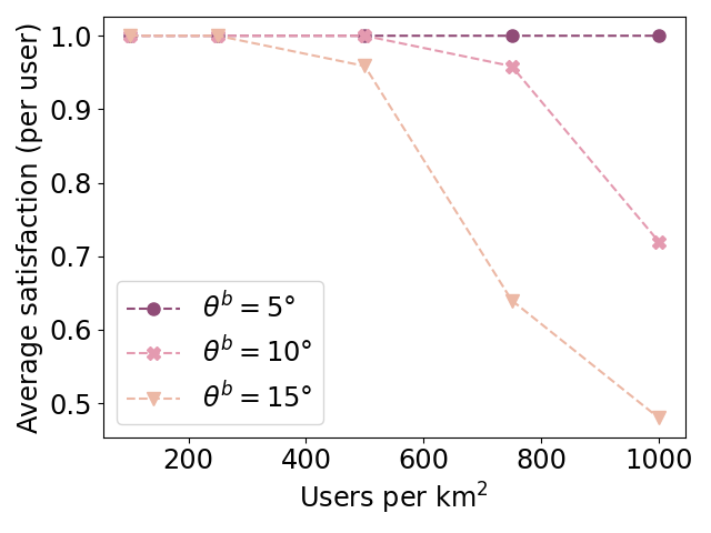
Fig. 3 shows the average per-user channel capacity and satisfaction level under increasing number of users for three BS beamwidths: , and . In all three cases, we assume that the user beamwidth is . As Fig.3(a) shows, narrower beams result in higher throughput for all user densities. For 200 users, operating with beams yields 2 throughput improvement over beams. The performance gap remains roughly the same under higher user densities. As seen in Fig.3(b), the satisfaction levels achieved by these beamwidths are the same under low user densities, e.g., 200 or 400 users. But, with increasing number of users, larger beamwidths result in lower satisfaction as some users may not be connected to any of the BSs. Note that the maximum number of users that can be served is upper-bounded by the total number of beams a BS has and , i.e., .
Finally, Fig. 3(c) plots the distribution of the number of connections per user for the considered beamwidths. From the figure, we observe that the number of connections per user decreases with increasing network load. For instance, for 100 users, average number of connections is around 9 for whereas it is around 2 for the same beamwidth when there are 1000 users in the network. Moreover, larger beamwidths result in lower number of connections. In a nutshell, the optimal degree of MC depends on the user density and the number of available beams in the network and also varies per user, illustrating the complexity of the optimal UA scheme. Under high user density such as 750 or 1000 users, larger beamwidths may result in some users being unserved as we see also zero connections for and in Fig.3(c). Moreover, the satisfaction level and the fraction of disconnected users are similar: users are almost never partially served. For example, for , and of the users are disconnected for 10 and 15 beamwidth respectively. This corresponds to a satisfaction level of and in Fig.3(b).
V-B Impact of the maximum number of users per beam
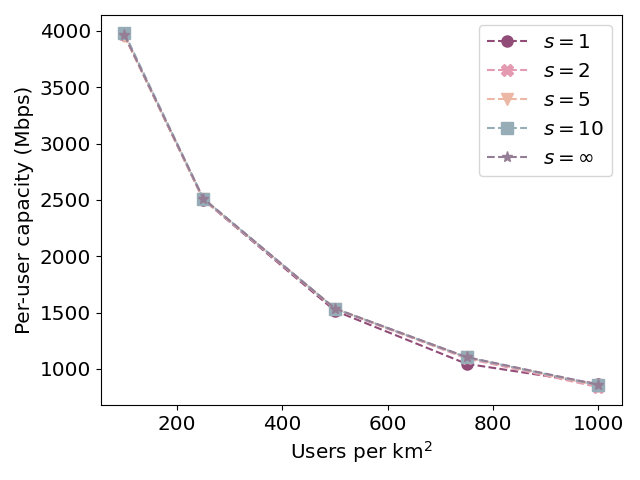
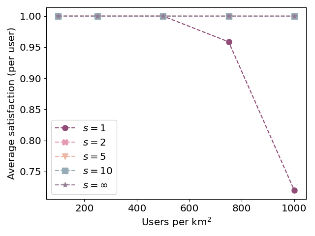
To derive insights on the impact of , we consider . As Fig. 4(a) shows, contrary to beamwidth, there is no significant difference in per-user capacity for different values of . However, in Fig. 4(b), we observe that allowing results in higher satisfaction as more users can be served in the same beam. Since adding more users to the same beam is also expected to result in higher overhead, in the following analysis, we focus on , as allowing two users per beam results in a high satisfaction while keeping the overhead low. Additionally, we set the BS beamwidth to to further decrease the overhead instead of .
V-C Distribution of the misalignment angle
Fig.5 shows the probability of connecting to the red BS in the optimal scheme, averaged over 1000 runs with . We rounded every location of the user in every simulation to the nearest integer value. The dark blue lines in this figure indicate that users who are in the middle of these beams have a high probability of connecting to that BS. Thus, for dynamic MC UA schemes, user locations and angular orientation are the key factors.

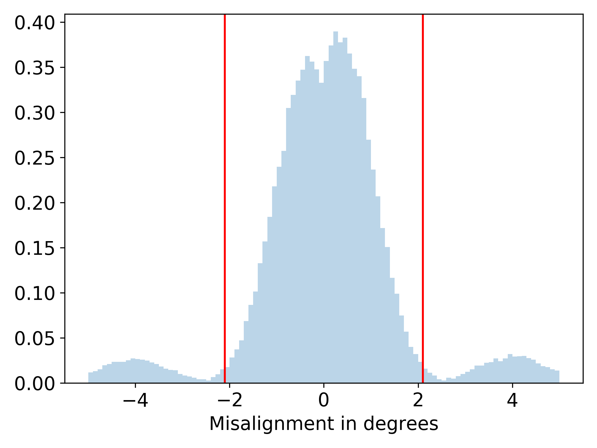
To illustrate this further, Fig. 6 shows a histogram of the misalignment of all existing links in the optimal UA scheme, i.e., the misalignment for all links such that . This figure has three ‘peaks’: one main peak in the middle, where the misalignment from both the BS’s side and the user’s side is small, and two smaller peaks, where the user’s misalignment is small. This again emphasizes that the angular orientation of a user is an important factor in the UA decision, as the misalignment distribution would be almost uniform if users connect to a BS disregarding the angular orientation with respect to the BSs. Moreover, Fig. 6 shows that the distance from the user to the BS also plays a role in this decision, as it shows that the connection probability decreases when users are further away from the red BS. Indeed, the path loss becomes higher for larger distances and therefore correctly aligned users closer to the red BS have a higher probability of connecting to it compared to further away users that have a lower SNR and thus lower throughput.
VI BEAM-ALIGN: User association considering beam misalignment
Based on the observation that misalignment is a key factor in deciding whether to connect to a BS, we devise beam-align whose pseudocode is shown in Algorithm (1). In beam-align, a user connects to every BS for which the BS-user misalignment is smaller than a threshold if that beam is not fully occupied yet. When the number of incoming requests for a beam is higher than the maximum allowed , the BS gives priority to users with high SNR to maximize the achieved throughput. The time that a BS serves a user is split equally among the users that are in the same beam. This algorithm can be run in a distributed manner at each BS without global knowledge of other BSs and users. For instance, at the beginning of a time slot, users can send their connection requests to the BSs and each BS can accept or reject the requests based on the misalignment and total number of received requests. To maintain the minimum signal quality for decodability of the signal, users can only send a connection request to a BS if the link-SNR is higher than . As the complexity of sorting the incoming requests according to the corresponding link SNRs (in Line 7) is dominant in comparison to deciding to accept a user’s request (in Line 8-Line 12), the complexity of running beam-align is .
The misalignment threshold in Alg.1 is based on simulations of the optimization scheme and is equal to twice the standard deviation of the BS-user misalignment of all links in the optimal scheme. This threshold can be derived offline by running the optimal algorithm under the applicable operation regime (e.g., the user beamwidth and BS beamwidths). The resulting values can then be saved at each BS to use while running this distributed heuristic.
In addition to the optimal scheme, we consider two baselines that both rely on SNR for UA: SNR-1 and SNR-dynamic. SNR-1 corresponds to UA in a single connectivity scenario where a user connects to the BS with the highest SNR, provided that a beam is available. In SNR-dynamic, users connect to a beam of a BS in order from highest to lowest SNR , until that beam is fully occupied ( shares). If the beam is not fully occupied, the remaining shares are divided equally among the connected users.
While misalignment and SNR are closely related as the signal degrades when the misalignment is large, beam-align and SNR-dynamic differ from each other as follows: beam-align results in a fairer UA scheme, as edge-users that are well-aligned will be preferred over users that are closer to the BS but misaligned. The SNR-dynamic algorithm on the other hand always prefers close-by users over edge-users, as close-by users will have a higher SNR in general.
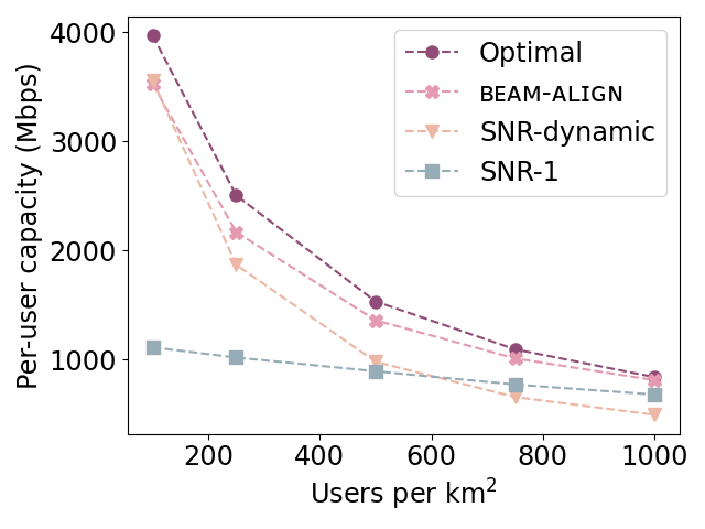
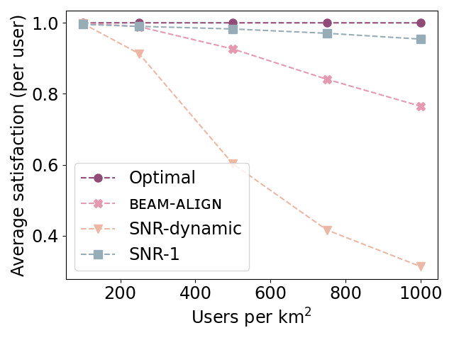
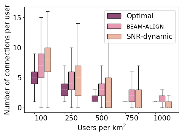
Fig. 7 shows the performance of the heuristics and the optimal solution in terms of capacity and satisfaction under increasing number of users. Fig. 7(a) shows that beam-align results in an average per-user capacity that is between and lower than the optimal scheme. beam-align also results in slightly fewer satisfied users for moderate user densities (Fig. 7(b)). Interestingly, the SNR-dynamic scheme results in a much lower per-user capacity and satisfaction level than the other UA schemes, especially in dense regimes. Compared to the optimal scheme, there is an average decrease in per-user capacity of .
Lastly, the SNR- scheme provides a more conservative UA scheme which results in a higher satisfaction level, but a lower per-user capacity in the sparse user regimes. Throughput benefits of MC over SC can be observed in Fig. 7(a) from the throughput gap between SNR-1 and the remaining MC schemes, which is 4 for 100 users. However, SNR-1 outperforms SNR-dynamic in terms of per-user capacity for user densities higher than . Together with the fact that the satisfaction level for is also higher compared to SNR-dynamic, this indicates that when resources are limited, uses will only benefit from MC if this is done in a smart way.
Fig. 7(c) shows the average number of links for UA schemes with MC. The average number of links per user is slightly higher in beam-align compared to the optimal. But, for high user densities, between to of the users are disconnected. The SNR-dynamic exhibits a similar behavior, but this scheme results in a higher number of connections per user for low densities, which then rapidly decreases in higher user densities. This rapid decrease in average number of links can be explained by the percentage of disconnected users, which is for , and increases up to for .
VII Robustness Analysis
In the previous sections, we have not accounted for possible imperfections that mmWave links might experience and consequently lead to low performance. Here, we consider three scenarios to investigate the robustness of optimal, beam-align and SNR-dynamic schemes under non-ideal conditions: namely, under blockage, rain and clustered users.
In case of blockage and rain, link quality will degrade as the path loss increases when a link is blocked or affected by rain. If the resulting link SNR is lower than , the received signal cannot be decoded at the receiver, resulting in a link failure. Therefore, we recalculate the average per-user throughput and satisfaction level in these scenarios and compare this to the scenario without blockage or rain. We refer to this baseline as Normal. To reflect more realistic user distributions rather than uniform distribution, we consider a clustered user distribution. In the following, we elaborate on these three scenarios.
-
•
Scenario I - Blockage: We simulate blockers according to the method described in [7]: for every blocker, we randomly generate a center, length, width and angle uniformly from a certain range, which denotes a rectangular area in the plane that is blocked. This process is done iteratively until the total blocker area is 10% of the considered area. We assume that the blockers are higher than the link between a user and a BS, and therefore we ignore the height of the blockers. Based on this set-up with blockers and the given UA schemes, we determine whether a link is blocked (nlos) or not (los), resulting in the real path loss of that link as described in Eqs.(2) and (3).
-
•
Scenario II - Rain: mmWave links might fail under heavy rain due to the increased path loss caused by additional attenuation. To investigate how our UA schemes will be affected by rain, we model the attenuation loss () due to rain as in [41]:
(14) (15) where , [40] for GHz band and is the rain rate in mm/h. In our evaluation, we consider three rain intensities: 2.5 mm/h (light rain), 25 mm/h (heavy rain) and 150 mm/h (monsoon) [28].
-
•
Scenario III - Clustered Users: As user mobility follows some social patterns, the resulting user location distribution resembles a clustered distribution more than a uniform distribution. To account for this fact, we use a Matérn cluster process to model the clustered users [9]. In our setting, this point process consists of a group of 30 parent points that are simulated by a PPP. Around these parents, we then generate a group of offspring points, uniformly distributed within a radius of m reflecting the coverage radius of a mmWave transmitter. Contrary to the other two scenarios, where we investigate the existing UA scheme with increased path loss, in this scenario, we simulate clustered users as a new scenario.
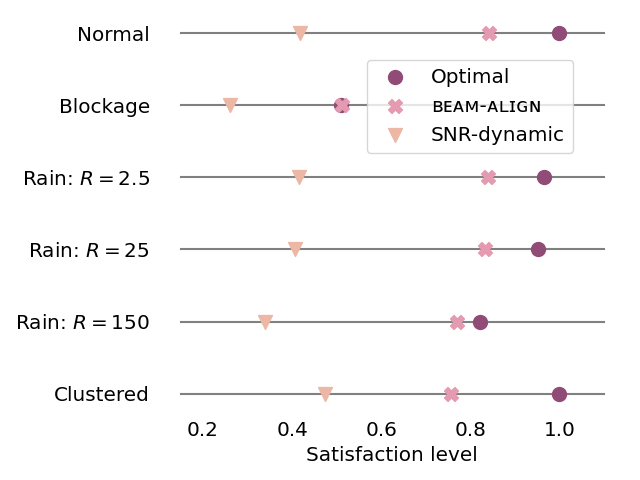
Fig. 8 shows the average per-user capacity (Fig.8(a)) and satisfaction level (Fig.8(b)) for all studied UA schemes. As we can see in Fig.8(a), beam-align performs close to optimal with an optimality gap varying from . Meanwhile, SNR-dynamic results in significantly lower capacity in all scenarios. The capacity gap between SNR-dynamic and beam-align varies from . Similar to Fig.7(a), SNR-1 outperforms SNR-dynamic for with a capacity gap between . Interesting, SNR-1 also leads to higher satisfaction level compared to SNR-dynamic in this scenario. This shows that MC is only beneficial when applied in a smart way. The stable performance difference between beam-align and the optimal schemes indicates that beam-align is robust to different operating conditions. Comparing the normal and blocked scenario, we observe that per-user capacity drops by 50% in the existence of blockers. To mitigate this performance loss, UA schemes can proactively consider the appearance of blockers when deciding on user association and determine the connections based on possible loss of line-of-sight.
Regarding satisfaction levels, in Fig.8(b), we observe that beam-align achieves almost the same satisfaction level as the optimal scheme under blockage and rain. Interestingly, the satisfaction level for beam-align in the blocked and rain scenarios is close to the optimal scheme, which confirms the robustness of beam-align. In general, all UA schemes are affected similarly in these scenarios. Moreover, Fig. 8 shows that clustered users and light rain will not affect the network as much as blockages in terms of average capacity and satisfaction.

VIII Discussion
In this section, we discuss two shortcomings of our work: limited consideration of overheads due to beamforming and MC and homogeneous user requirements.
First, in our model, we considered a fixed time overhead () for beam alignment. However, prior studies show that beam alignment overhead and the resulting performance degradation due to misalignment is larger for smaller beamwidths [14]. Hence, our conclusions derived from Fig.3 which suggests that smaller beamwidths enable higher throughput may not hold if beamforming overhead is considerable. Moreover, for high mobility scenarios, maintaining connections to the BS with smaller beamwidths becomes difficult. Hence, considering an overhead factor that depends on the BS beamwidth is an interesting future research direction. Moreover, more sophisticated antenna operation can be considered, e.g., BSs can adapt their beam widths depending on the network states, e.g., user density and mobility.
Similarly, overheads due to MC such as scheduling control messaging are not considered in this work. Consequently, under beam-align, some users are connected to as many as 14 BSs which might not be feasible in a realistic setting as the overhead will increase due to the inter-BS communication for packet splitting. Therefore, adding an extra constraint to the number of connections of user in (7) can limit the maximum number of connections to an upper bound. However, general trends observed in this paper are not expected to change, as longer-distance connections have lower spectral efficiency and therefore do not contribute much to total throughput of the user. Further investigation of the cost of MC and beam alignment can provide a more thorough understanding of the impact of MC and beamwidths.
The second limitation is due to our assumption of users with identical requirements. A realistic scenario can also include heterogeneous rate or reliability requirements. To account for this, we could expand beam-align by for example dividing the time in a beam heterogeneously depending on the user requirements or by ensuring a minimal number of connections for users requiring high reliability. Additionally, we assumed that BSs have identical antennas, e.g., beamwidths and fixed beam directions. We believe that further investigation in more dynamic antenna configurations can reveal even more benefits of MC and beamforming.
IX Conclusion
Multi-connectivity can facilitate higher throughput and increased robustness against channel impairments frequent in mmWave networks. However, determining the optimal number of connections and user-BS association remains a challenge. In this paper, we formulated an optimization problem that solves the user association problem for mmWave networks with multi-connectivity and beamforming, while maintaining a high user satisfaction level. Our numerical investigations showed that a smaller BS beamwidth results in a higher per-user capacity and a higher satisfaction level. Inspired by the observations on the optimal association scheme, we designed beam-align that only needs local information based on the misalignment between the geographical angle of a user-BS link and the boresight angle of the beam to which this user connects. We showed that beam-align performs close to optimal in terms of per-user capacity while still keeping a moderately high satisfaction level. Moreover, beam-align always outperforms SNR-dynamic and SNR- which use only SNR information to determine the user-BS association(s). Finally, we investigated the performance of the optimal scheme, beam-align and SNR-dynamic under scenarios with blockage, rain, and clustered users. We observed that SNR-dynamic scheme is inferior to the optimal and beam-align, and both optimal and beam-align are robust to different settings.
References
- [1] 3GPP, 3rd Generation Partnership Project; Technical Specification Group Radio Access Network; Study on channel model for frequencies from 0.5 to 100 GHz (Release 16, technical specification (ts), 3rd Generation Partnership Project (3GPP), 2019. 3GPP TR 38.901 V16.1.0 (2019-12), https://www.3gpp.org/ftp/Specs/archive/38_series/38.901/.
- [2] S. Aghashahi, S. Aghashahi, Z. Zeinalpour-Yazdi, A. Tadaion, and A. Asadi, Stochastic modeling of beam management in mmWave vehicular networks, IEEE Transactions on Mobile Computing, (2021).
- [3] A. Alizadeh and M. Vu, Distributed user association in B5G networks using early acceptance matching game, IEEE Transactions on Wireless Communications, 20 (2020), pp. 2428–2441.
- [4] A. Alkhateeb, Y.-H. Nam, M. S. Rahman, J. Zhang, and R. W. Heath, Initial beam association in millimeter wave cellular systems: Analysis and design insights, IEEE Transactions on Wireless Communications, 16 (2017), pp. 2807–2821.
- [5] M. L. Attiah, A. A. M. Isa, Z. Zakaria, M. Abdulhameed, M. K. Mohsen, and I. Ali, A survey of mmWave user association mechanisms and spectrum sharing approaches: an overview, open issues and challenges, future research trends, Wireless Networks, 26 (2020), pp. 2487–2514.
- [6] T. Bai and R. W. Heath, Coverage and rate analysis for millimeter-wave cellular networks, IEEE Transactions on Wireless Communications, 14 (2014), pp. 1100–1114.
- [7] T. Bai, R. Vaze, and R. W. Heath, Analysis of blockage effects on urban cellular networks, IEEE Transactions on Wireless Communications, 13 (2014), pp. 5070–5083.
- [8] A. S. Cacciapuoti, Mobility-aware user association for 5G mmWave networks, IEEE Access, 5 (2017), pp. 21497–21507.
- [9] Y. J. Chun, M. O. Hasna, and A. Ghrayeb, Modeling heterogeneous cellular networks interference using Poisson cluster processes, IEEE Journal on Selected Areas in Communications, 33 (2015), pp. 2182–2195.
- [10] M. Gapeyenko, V. Petrov, D. Moltchanov, M. R. Akdeniz, S. Andreev, N. Himayat, and Y. Koucheryavy, On the degree of multi-connectivity in 5G millimeter-wave cellular urban deployments, IEEE Transactions on Vehicular Technology, 68 (2019), pp. 1973–1978.
- [11] M. Giordani, M. Mezzavilla, S. Rangan, and M. Zorzi, Multi-connectivity in 5g mmwave cellular networks, in 2016 Mediterranean Ad Hoc Networking Workshop (Med-Hoc-Net), 2016, pp. 1–7.
- [12] V. K. Gupta, S. K. Singh, and G. S. Kasbekar, Stability analysis of simple and online user association policies for millimeter wave networks, IEEE Access, 9 (2021), pp. 62405–62429.
- [13] Gurobi Optimization, LLC, Gurobi Optimizer Reference Manual, 2022.
- [14] M. K. Haider and E. W. Knightly, Mobility resilience and overhead constrained adaptation in directional 60 GHz WLANs: protocol design and system implementation, in Proceedings of the 17th ACM International Symposium on Mobile Ad Hoc Networking and Computing, 2016, pp. 61–70.
- [15] D. C. Halperin, Simplifying the configuration of 802.11 wireless networks with effective SNR, arXiv preprint arXiv:1301.6644, (2013).
- [16] O. Kanhere, A. Chopra, A. Thornburg, T. S. Rappaport, and S. S. Ghassemzadeh, Performance impact analysis of beam switching in millimeter wave vehicular communications, in 2021 IEEE 93rd Vehicular Technology Conference (VTC2021-Spring), IEEE, 2021, pp. 1–7.
- [17] J. Kim, J. Park, S. Kim, S.-L. Kim, K. W. Sung, and K. S. Kim, Millimeter-wave interference avoidance via building-aware associations, IEEE Access, 6 (2018), pp. 10618–10634.
- [18] R. Liu, M. Lee, G. Yu, and G. Y. Li, User association for millimeter-wave networks: A machine learning approach, IEEE Transactions on Communications, 68 (2020), pp. 4162–4174.
- [19] R. Liu and G. Yu, User association for millimeter-wave ultra-reliable low-latency communications, IEEE Wireless Communications Letters, (2020).
- [20] R. Liu, G. Yu, J. Yuan, and G. Y. Li, Resource management for millimeter-wave ultra-reliable and low-latency communications, IEEE Transactions on Communications, (2020).
- [21] D. Liue, L. Wang, Y. Chen, M. Elkashlan, K.-K. Wong, R. Schober, and L. Hanzo, User association in 5G networks: A survey and an outlook, IEEE Communications Surveys & Tutorials, 18 (2016), pp. 1018–1044.
- [22] M. Mezzavilla, S. Goyal, S. Panwar, S. Rangan, and M. Zorzi, An MDP model for optimal handover decisions in mmWave cellular networks, in 2016 European conference on networks and communications (EuCNC), IEEE, 2016, pp. 100–105.
- [23] T. Nadeem, Analysis and enhancements for IEEE 802.11 networks using directional antenna with opportunistic mechanisms, IEEE Transactions on Vehicular Technology, 59 (2010), pp. 3012–3024.
- [24] M. F. Özkoç, A. Koutsaftis, R. Kumar, P. Liu, and S. S. Panwar, The impact of multi-connectivity and handover constraints on millimeter wave and terahertz cellular networks, IEEE Journal on Selected Areas in Communications, 39 (2021), pp. 1833–1853.
- [25] P. Paul, H. Wu, and C. Xin, BOOST: A user association and scheduling framework for beamforming mmWave networks, IEEE Transactions on Mobile Computing, (2020).
- [26] J. Perdomo, M. Ericsson, M. Nordberg, and K. Andersson, User performance in a 5G multi-connectivity ultra-dense network city scenario, in 2020 IEEE 45th Conference on Local Computer Networks (LCN), IEEE, 2020, pp. 195–203.
- [27] V. Petrov, D. Solomitckii, A. Samuylov, M. A. Lema, M. Gapeyenko, D. Moltchanov, S. Andreev, V. Naumov, K. Samouylov, M. Dohler, et al., Dynamic multi-connectivity performance in ultra-dense urban mmWave deployments, IEEE Journal on Selected Areas in Communications, 35 (2017), pp. 2038–2055.
- [28] Z. Pi and F. Khan, An introduction to millimeter-wave mobile broadband systems, IEEE communications magazine, 49 (2011), pp. 101–107.
- [29] K. Sakaguchi, T. Haustein, S. Barbarossa, E. C. Strinati, A. Clemente, G. Destino, A. Pärssinen, I. Kim, H. Chung, J. Kim, et al., Where, when, and how mmWave is used in 5G and beyond, IEICE Transactions on Electronics, 100 (2017), pp. 790–808.
- [30] M. Series, Minimum requirements related to technical performance for IMT-2020 radio interface (s), Report, (2017), pp. 2410–0.
- [31] H. Shokri-Ghadikolaei, Y. Xu, L. Gkatzikis, and C. Fischione, User association and the alignment-throughput tradeoff in millimeter wave networks, in 2015 IEEE 1st International Forum on Research and Technologies for Society and Industry Leveraging a better tomorrow (RTSI), IEEE, 2015, pp. 100–105.
- [32] E. Sopin, D. Moltchanov, A. Daraseliya, Y. Koucheryavy, and Y. Gaidamaka, User association and multi-connectivity strategies in joint terahertz and millimeter wave 6G systems, arXiv preprint arXiv:2206.03108, (2022).
- [33] M. T. Suer, C. Thein, H. Tchouankem, and L. Wolf, Multi-connectivity as an enabler for reliable low latency communications - an overview, IEEE Communications Surveys and Tutorials, 22 (2020), pp. 156–169.
- [34] C. Tatino, I. Malanchini, N. Pappas, and D. Yuan, Maximum throughput scheduling for multi-connectivity in millimeter-wave networks, in 2018 16th International Symposium on Modeling and Optimization in Mobile, Ad Hoc, and Wireless Networks (WiOpt), IEEE, 2018, pp. 1–6.
- [35] C. Tatino, N. Pappas, I. Malanchini, L. Ewe, and D. Yuan, Learning-based link scheduling in millimeter-wave multi-connectivity scenarios, in ICC 2020-2020 IEEE International Conference on Communications (ICC), IEEE, 2020, pp. 1–6.
- [36] I. Toyoda and T. Seki, Antenna model and its application to system design in the millimeter-wave wireless personal area networks standard, NTT Tech. Rev, 9 (2011), pp. 1–5.
- [37] Y.-R. Tsai and W.-H. Chen, High efficiency beam alignment based on multi-modal beam patterns for massive MIMO antenna systems, IEEE Transactions on Vehicular Technology, 70 (2021), pp. 13035–13046.
- [38] L. Weedage, C. Stegehuis, and S. Bayhan, Impact of multi-connectivity on channel capacity and outage probability in wireless networks, arXiv preprint arXiv:2104.09823, (2021).
- [39] Y. Zhang, L. Dai, and E. W. Wong, Optimal BS deployment and user association for 5G millimeter wave communication networks, IEEE Transactions on Wireless Communications, 20 (2020), pp. 2776–2791.
- [40] Z. Zhang, J. Ryu, S. Subramanian, and A. Sampath, Coverage and channel characteristics of millimeter wave band using ray tracing, in 2015 IEEE International Conference on Communications (ICC), IEEE, 2015, pp. 1380–1385.
- [41] Z.-w. Zhao, M.-g. Zhang, and Z.-s. Wu, Analytic specific attenuation model for rain for use in prediction methods, International Journal of Infrared and millimeter waves, 22 (2001), pp. 113–120.