Transport of multispecies ion crystals through a junction in an RF Paul trap
Abstract
We report on the first demonstration of transport of a multispecies ion crystal through a junction in an RF Paul trap. The trap is a two-dimensional surface-electrode trap with an X junction and segmented control electrodes to which time-varying voltages are applied to control the shape and position of potential wells above the trap surface. We transport either a single 171Yb+ ion or a crystal composed of a 138Ba+ ion cotrapped with the 171Yb+ ion to any port of the junction. We characterize the motional excitation by performing multiple round-trips through the junction and back to the initial well position without cooling. The final excitation is then measured using sideband asymmetry. For a single 171Yb+ ion, transport with a average speed induces between and quanta of excitation per round trip, depending on the exit port. For a Ba-Yb crystal, transport at the same speed induces between and quanta per round trip of excitation to the axial center of mass mode. Excitation in the axial stretch mode ranges from to quanta per round trip.
Trapped ions are one of the leading candidate systems for scalable quantum computers [1, 2]. In a trapped-ion quantum computer, quantum information is stored in the internal atomic states of the qubit ions, and multi-qubit gates are usually performed by coupling the internal states of two qubits with a common motional mode [3]. Qubit connectivity can be achieved through control of trapping potentials created by surface-electrode ion traps [4, 5, 6].
All-to-all connectivity can be achieved either by including all qubits in a single crystal [7] or by use of a quantum charge coupled device (qCCD) architecture [8, 9], where gates are performed on small chains of ions, which can be reordered and reconfigured. Current trapped-ion quantum computers [9, 7, 10] use effectively one-dimensional (linear trap) geometries. In such linear traps, sorting ions between gates is done through a combination of potential well splits [11], rotations [12], and linear transports [11, 13]. Sorting on two dimensional grids additionally requires transport through junctions to connect linear sections. There have been demonstrations of ion transport through several junction geometries, including T junctions [14], wafer-trap [15, 16, 17] and surface [18, 19] X junctions, and Y junctions [20, 21, 22]. However, there has been no reported effort to transport a multispecies ion crystal through the junction. Doing so allows for simultaneous transport of a sympathetic coolant ion with each qubit, simplifying the sorting algorithm in a large-scale quantum computer.
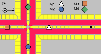
In this Letter, we present fast, low-excitation junction transport of both single ions and multispecies ion crystals through a microfacbricated surface trap X junction fabricated at Honeywell (represented in Figure 1). For single species transport, we used a single 171Yb+ ion, and for multispecies transport, we used a crystal composed of one 138Ba+ ion cotrapped with one 171Yb+ ion (referred to as a Ba-Yb crystal in the remainder of this paper). For both single species and multispecies transport, we were able to transport through the X junction to each of the legs (labeled M1-M4 in Figure 1) and back to the starting position with low excitation and without reordering. Additionally, we studied the impacts of transport speed, trap electrode drive voltage drifts, and external stray electric fields to ion excitation and survivability.
| Crystal | Zone | Round Trip Excitation (quanta) |
|---|---|---|
| Yb | M2 | |
| Yb | M3 | |
| Yb | M4 |
Ion surface traps consist of two classes of electrodes: RF rails and segmented control electrodes. When a radio-frequency (RF) oscillating voltage is applied to the RF rails, charged particles in the vicinity undergo micromotion at the RF frequency. This interaction leads to an effective potential , known as the pseudopotential [23, 1]. For each control electrode, we calculate a basis function that describes its contribution to the electrical potential at when 1 V is applied to the electrode. The total potential is given by
| (1) |
where the are the voltages applied to each control electrode. For a given target trapping well (e.g., a potential with a minimum at a defined location and a set of trap frequencies), we can solve for the using a constrained optimization method [17, 24]. To create a waveform of voltages that transports an ion between two locations, we solve for a series of potential wells along the transport path. We then interpolate between these solutions to generate the time-dependent waveform.
The laws of electrostatics place constraints on the sorts of potentials that can be generated. We define the total confinement , where is the frequency of the normal motional mode of harmonic oscillation of a single ion. Because the control electrodes necessarily produce fields with zero divergence, and depends only on the pseudopotential. In other words, no set of control voltages can change the total confinement at a given point – they can only re-distribute frequency between modes.
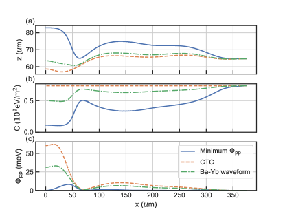
Transport of ions in surface traps have typically followed the path of minimum pseudopotential, which minimizes micromotion and sensitivity to noise on the RF source. In an X junction, the total confinement along the pseudopotential minimum near the center of the junction drops significantly [25]. In this trap, the total confinement at the center of the junction is about 1/8 of its maximum value along the path, as seen in Figure 2b.
A successful strategy in surface-trap junction transport involves moving the ion off of the path of minimum pseudopotential [18, 22]. We define the path of constant total confinement (CTC) as a path directly below (in ) the path of minimum pseudopotential, with a height that varies to keep constant along the path. We choose the value of so that the path of CTC and the path of minimum pseudopotential intersect above the center of M1. Note that this definition of the path of CTC is independent of ion species. As seen in Figure 2a, the path of CTC drops significantly toward the trap relative to the path of minimum pseudopotential.
For single species junction transport, we generated four waveforms that follow the path of CTC from the junction center to each of the measurement zones (M1, M2, M3, and M4). We define the axial direction to be for M1 and M3, and for M2 and M4 and define the two perpendicular axes to be the radial directions. The total confinement along the path permits waveform solutions that maintain a constant axial trap frequency of and a large frequency separation of all motional modes over the entire trajectory, preventing transfer of excitation between the different motional modes [17]. In addition, we created two waveforms that rotate the principal axes of a single well at the center of the junction by 90 degrees, which adiabatically convert the axial direction from to and back. The average speed of the transport can be set by linearly scaling the waveform playout in time.
Each single ion transport experiment begins with a 171Yb+ ion trapped in zone M1. We initialize the system by performing Doppler and sideband cooling [26] to cool all three motional modes to less than 0.1 quanta of excitation each. We then transport the ion to the center of the junction with the time-reversed junction–M1 waveform. To transport to M3, we apply the junction–M3 waveform. To transport to M2 or M4, we rotate the principal axes while the well center is stationary at the center of the junction before applying the junction–M2 or junction–M4 waveform. We hold the well center position constant for and then reverse the transport sequence back to M1. The final excitation is measured with Raman sideband asymmetry on the motional mode in the axial direction [26]. To separate non-zero initial temperature from excitation due to transport, we measure the excitation as a function of the number of round-trips and extract the slope, recorded in Table 1 for transports with average speeds of .
Multispecies crystals present a particular challenge for junction transport because the pseudopotential is proportional to the inverse of the ion mass [23], while the potential due to control electrodes only depends on the ion charge and is thus common to both species. This affects junction transport in two significant ways:
-
1.
At approximately from the center of the junction, there is a local maximum of the pseudopotential (see Figure 2c), which corresponds to an axial anti-trapping potential. When making a transport waveform for a single ion species, our solution method takes this into account and holds the total axial curvature constant. However for the same waveform, an ion with a different mass will necessarily experience a changing axial curvature, which could lead to excess motional excitation or ion loss.
-
2.
The minimum of the total potential for an ion of one mass occurs at the location where the gradient of the potential from the control electrodes is equal and opposite to the gradient of the pseudopotential. However, the potential minimum for a second ion with a different mass will be at a different position.
Given sufficient degrees of freedom by the control voltages, the total potential for both ion species could be independently controlled. However, this is experimentally impractical since the spacing of an ion crystal is generally of the order of a few micrometers while the distance from the trap and the size of the control electrodes are both about . Instead, we create multispecies junction transport waveforms through a numerical optimization process. We parametrize possible transport waveforms using two degrees of freedom: the path height parameterized by the fraction of the distance between the CTC and the pseudopotential minimum, and the potential curvature in the axial direction. These degrees of freedom have several coupled effects:
-
1.
A larger axial curvature ensures that the total potential for both species remains trapping even at the peak of the anti-curvature of the pseudopotential, but for a given total confinement it reduces the potential curvature in the radial directions.
-
2.
The path height affects both the total confinement and the gradient of the pseudopotential at the ion crystal.
-
3.
The separation of the minima of the total potential for the different ion species is given by a combination of the gradient of the pseudopotential and the curvature in the vertical direction.
Because of the non-trivial coupling, an exhaustive exploration of the parameter space was employed to find successful transport waveforms. At each search point in parameter space, the Ba-Yb waveforms are generated assuming a single synthetic ion with a mass equal to the average ion mass in the Ba-Yb crystal, following the defined transport path, and with a constant total potential curvature in the axial direction. We use a numerical equations-of-motion solver to simulate the behavior of a Ba-Yb crystal during transport in the test waveform and note ion survival and non-adiabatic excitation. We found a broad region of low-excitation waveforms (see Supplemental Material) in parameter space centered around an axial curvature of (equivalent to a axial frequency for the synthetic ion) and a path height 80% of the way between the path of minimum pseudopotential and the path of CTC (dot-dashed green line in Figure 2). We use these parameters for multi-species junction transport for the data collected in the remainder of this paper.
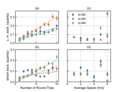
Figure 3 shows the experimental results for multispecies junction transport. We begin each experiment with a Ba-Yb crystal trapped in M1, with the 171Yb+ ion closer to the junction. A combination of EIT cooling on the 138Ba+ and sideband cooling on the 171Yb+ initilalizes the axial modes with less than 0.05 quanta of excitation, and the radial modes with less than 0.3 quanta of excitation. As in the single species transport experiments, we perform a variable number of round trips between M1 and the other three zones with an average speed of 4 m/s before measuring the excitation in both axial motional modes (center of mass and stretch). The extracted slopes, reported in Table 2, indicate that less than or equal to 0.03 quanta of excitation are added per round trip. In addition, we examined the impact of transport speed on induced excitation, with results shown in Figure 3c-d. We find negligible excitation up to 6 m/s. Above this speed, we see evidence of coherent motional excitation in the center of mass (c. m.) mode, which is difficult to quantify with sideband asymmetry measurements. Finally, in the Supplemental Material, we report on the sensitivity of junction transport to drifts in the amplitude of the RF drive and to stray electric fields.
| Crystal | Mode | Zone | Round Trip Excitation (quanta) |
|---|---|---|---|
| Ba-Yb | c. m. | M2 | |
| Ba-Yb | c. m. | M3 | |
| Ba-Yb | c. m. | M4 | |
| Ba-Yb | stretch | M2 | |
| Ba-Yb | stretch | M3 | |
| Ba-Yb | stretch | M4 |
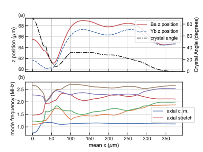
We numerically simulate the properties of a Ba-Yb crystal using the pseudopotential separately scaled by mass for each ion species. In Figure 4a, we plot the simulated equilibrium positions of a Ba-Yb crystal during transport from M1 to the junction center. (The qualitative features of this waveform are shared by all successful Ba-Yb waveforms found in the numerical optimization.) When the crystal is near M1, where the trapping potential is similar to that generated in a linear surface trap, the crystal is oriented in the axial direction with the 171Yb+ ion closer to the junction. As the crystal approaches the center of the junction, due to different contributions to the total potential from the pseudopotential, it rotates to be perpendicular to the trap (the direction), regardless of the starting leg. When the crystal moves away from the junction center, either reversing its motion or moving into one of the other three legs, the crystal rotates back to a horizontal orientation, but always with the 171Yb+ closer to the junction, without an explicit rotation waveform. In Figure 4b, we plot the normal mode frequencies versus ion crystal location. Near , there are several normal mode crossings that couple some of the radial modes to the axial modes during the transport, complicating analysis of transport performed without pre-cooling the radial modes. In experiments where we pre-cool all motional modes, we see no evidence of excitation leaking into the measured axial modes and can conclude that the motional excitation in the radial modes is low.
In this Letter, we have presented the first implementation of junction transport of a multispecies ion crystal, which provides an important tool for minimizing circuit times in a two-dimensional ion trap quantum computer. We find that the transport adds very little excitation to all axial motional degrees of freedom at average speeds up to . In future work, further analysis of the waveform generation method and numerical optimization of the waveform may allow us to control or eliminate the crossing of motional modes during transport or to increase the speed of transport without additional coherent motional excitation [27]. In addition, to demonstrate scalability, we plan to develop the parallel transport of multiple ion crystals through neighboring junctions.
Acknowledgements.
The authors would like to acknowledge Jonathan Andreasen at the Georgia Tech Research Institue for assistance with the surface trap design and Steven Moses at Quantinuum for helpful comments on the text. We thank the entire Quantinuum team for many additional techical and supporting contributions.References
- Wineland et al. [1998] D. J. Wineland, C. Monroe, W. M. Itano, D. Leibfried, B. E. King, and D. M. Meekhof, Experimental issues in coherent quantum-state manipulation of trapped atomic ions, Journal of research of the National Institute of Standards and Technology 103, 259 (1998).
- Kaushal et al. [2020] V. Kaushal, B. Lekitsch, A. Stahl, J. Hilder, D. Pijn, C. Schmiegelow, A. Bermudez, M. Müller, F. Schmidt-Kaler, and U. Poschinger, Shuttling-based trapped-ion quantum information processing, AVS Quantum Science 2, 014101 (2020).
- Cirac and Zoller [1995] J. I. Cirac and P. Zoller, Quantum computations with cold trapped ions, Phys. Rev. Lett. 74, 4091 (1995).
- Seidelin et al. [2006] S. Seidelin, J. Chiaverini, R. Reichle, J. J. Bollinger, D. Leibfried, J. Britton, J. H. Wesenberg, R. B. Blakestad, R. J. Epstein, D. B. Hume, W. M. Itano, J. D. Jost, C. Langer, R. Ozeri, N. Shiga, and D. J. Wineland, Microfabricated surface-electrode ion trap for scalable quantum information processing, Phys. Rev. Lett. 96, 253003 (2006).
- Leibrandt et al. [2009] D. Leibrandt, J. Labaziewicz, R. Clark, I. Chuang, R. Epstein, C. Ospelkaus, J. Wesenberg, J. Bollinger, D. Leibfried, D. Wineland, et al., Demonstration of a scalable, multiplexed ion trap for quantum information processing, Quantum Information & Computation 9, 901 (2009).
- Schulz et al. [2008] S. A. Schulz, U. Poschinger, F. Ziesel, and F. Schmidt-Kaler, Sideband cooling and coherent dynamics in a microchip multi-segmented ion trap, New Journal of Physics 10, 045007 (2008).
- Wright et al. [2019] K. Wright, K. M. Beck, S. Debnath, J. Amini, Y. Nam, N. Grzesiak, J.-S. Chen, N. Pisenti, M. Chmielewski, C. Collins, et al., Benchmarking an 11-qubit quantum computer, Nature communications 10, 1 (2019).
- Kielpinski et al. [2002] D. Kielpinski, C. Monroe, and D. J. Wineland, Architecture for a large-scale ion-trap quantum computer, Nature 417, 709 (2002).
- Pino et al. [2021] J. M. Pino, J. M. Dreiling, C. Figgatt, J. P. Gaebler, S. A. Moses, M. Allman, C. Baldwin, M. Foss-Feig, D. Hayes, K. Mayer, et al., Demonstration of the trapped-ion quantum ccd computer architecture, Nature 592, 209 (2021).
- Pogorelov et al. [2021] I. Pogorelov, T. Feldker, C. D. Marciniak, L. Postler, G. Jacob, O. Krieglsteiner, V. Podlesnic, M. Meth, V. Negnevitsky, M. Stadler, et al., Compact ion-trap quantum computing demonstrator, PRX Quantum 2, 020343 (2021).
- Rowe et al. [2002] M. Rowe, A. Ben-Kish, B. Demarco, D. Leibfried, V. Meyer, J. Beall, J. Britton, J. Hughes, W. Itano, B. Jelenković, et al., Transport of quantum states and separation of ions in a dual rf ion trap, Quantum Information and Computation 2, 257 (2002).
- Splatt et al. [2009] F. Splatt, M. Harlander, M. Brownnutt, F. Zähringer, R. Blatt, and W. Hänsel, Deterministic reordering of 40Ca+ions in a linear segmented paul trap, New Journal of Physics 11, 103008 (2009).
- Home et al. [2009] J. P. Home, D. Hanneke, J. D. Jost, J. M. Amini, D. Leibfried, and D. J. Wineland, Complete methods set for scalable ion trap quantum information processing, Science 325, 1227 (2009).
- Hensinger et al. [2006] W. Hensinger, S. Olmschenk, D. Stick, D. Hucul, M. Yeo, M. Acton, L. Deslauriers, C. Monroe, and J. Rabchuk, T-junction ion trap array for two-dimensional ion shuttling, storage, and manipulation, Applied Physics Letters 88, 034101 (2006).
- Blakestad et al. [2009] R. B. Blakestad, C. Ospelkaus, A. P. VanDevender, J. M. Amini, J. Britton, D. Leibfried, and D. J. Wineland, High-fidelity transport of trapped-ion qubits through an -junction trap array, Phys. Rev. Lett. 102, 153002 (2009).
- Decaroli et al. [2021] C. Decaroli, R. Matt, R. Oswald, C. J. Axline, M. Ernzer, J. Flannery, S. Ragg, and J. P. Home, Design, fabrication and characterisation of a micro-fabricated stacked-wafer segmented ion trap with two x-junctions., Quantum Science and Technology (2021).
- Blakestad et al. [2011] R. B. Blakestad, C. Ospelkaus, A. P. VanDevender, J. H. Wesenberg, M. J. Biercuk, D. Leibfried, and D. J. Wineland, Near-ground-state transport of trapped-ion qubits through a multidimensional array, Phys. Rev. A 84, 032314 (2011).
- Wright et al. [2013] K. Wright, J. M. Amini, D. L. Faircloth, C. Volin, S. C. Doret, H. Hayden, C. Pai, D. W. Landgren, D. Denison, T. Killian, et al., Reliable transport through a microfabricated x-junction surface-electrode ion trap, New Journal of Physics 15, 033004 (2013).
- Zhang et al. [2022] C. Zhang, K. K. Mehta, and J. P. Home, Optimization and implementation of a surface-electrode ion trap junction (2022), arXiv:2201.12579 .
- Amini et al. [2010] J. M. Amini, H. Uys, J. H. Wesenberg, S. Seidelin, J. Britton, J. J. Bollinger, D. Leibfried, C. Ospelkaus, A. P. VanDevender, and D. J. Wineland, Toward scalable ion traps for quantum information processing, New journal of Physics 12, 033031 (2010).
- Moehring et al. [2011] D. L. Moehring, C. Highstrete, D. Stick, K. M. Fortier, R. Haltli, C. Tigges, and M. G. Blain, Design, fabrication and experimental demonstration of junction surface ion traps, New Journal of Physics 13, 075018 (2011).
- Shu et al. [2014] G. Shu, G. Vittorini, A. Buikema, C. Nichols, C. Volin, D. Stick, and K. R. Brown, Heating rates and ion-motion control in a y-junction surface-electrode trap, Physical Review A 89, 062308 (2014).
- Drees and Paul [1964] J. Drees and W. Paul, Beschleunigung von elektronen in einem plasmabetatron, Zeitschrift für Physik 180, 340 (1964).
- Hucul et al. [2008] D. Hucul, M. Yeo, S. Olmschenk, C. Monroe, W. Hensinger, and J. Rabchuk, On the transport of atomic ions in linear and multidimensional ion trap arrays, Quantum Information & Computation 8, 501 (2008).
- Wesenberg [2009] J. H. Wesenberg, Ideal intersections for radio-frequency trap networks, Phys. Rev. A 79, 013416 (2009).
- Monroe et al. [1995] C. Monroe, D. M. Meekhof, B. E. King, S. R. Jefferts, W. M. Itano, D. J. Wineland, and P. Gould, Resolved-sideband raman cooling of a bound atom to the 3d zero-point energy, Phys. Rev. Lett. 75, 4011 (1995).
- Palmero et al. [2014] M. Palmero, R. Bowler, J. P. Gaebler, D. Leibfried, and J. G. Muga, Fast transport of mixed-species ion chains within a paul trap, Phys. Rev. A 90, 053408 (2014).