Room temperature surface multiferroicity in Y2NiMnO6 nanorods
Abstract
We report observation of surface-defect-induced room temperature multiferroicity - surface ferromagnetism ( at 50 kOe 0.005 emu/g), ferroelectricity ( 2 nC/cm2), and significantly large magnetoelectric coupling (decrease in by 80% under 15 kOe field) - in nanorods (diameter 100 nm) of double perovskite Y2NiMnO6 compound. In bulk form, this system exhibits multiferroicity only below its magnetic transition temperature 70 K. On the other hand, the oxygen vacancies, formed at the surface region (thickness 10 nm) of the nanorods, yield long-range magnetic order as well as ferroelectricity via Dzyloshinskii-Moriya exchange coupling interactions with strong Rashba spin-orbit coupling. Sharp drop in under magnetic field indicates strong cross-coupling between magnetism and ferroelectricity as well. Observation of room temperature magnetoelectric coupling in nanoscale for a compound which, in bulk form, exhibits multiferroicity only below 70 K underscores an alternative pathway for inducing magnetoelectric multiferroicity via surface defects and, thus, in line with magnetoelectric property observed, for example, in domain walls or boundaries or interfaces of heteroepitaxially grown thin films which do not exhibit such features in their bulk.
pacs:
75.70.Cn, 75.75.-cI Introduction
Alongside comprehensive investigation of multiferroicity in single-phase Type-I and Type-II systems and composites, in recent time, an alternative paradigm is emerging where spontaneously formed (such as domain wall or boundaries) and/or artificially fabricated (such as nanosized and heteroepitaxial architectures) surface/interface regions are found to be hosting the magnetic and ferroelectric orders and offering the test bed for inducing coupling among the order parameters Fiebig ; Zutic ; Spaldin . For example, ferroelastic domain walls in SrTiO3, below its structural phase transition (from cubic to tetragonal) at 105 K, host ferroelectric order and, therefore, respond to electrical tuning and, in turn, change the magnetic domain structure in LaSrMnO3 deposited on the SrTiO3 substrate Salje . It has also been pointed out in a theoretical work Bellaiche that, in orthoferrite SmFeO3, magnetic domain boundaries could be polar while the domains themselves are not. Surface and interface regions in many systems have been found to be topologically protecting the magnetic and electrical vortices with often a coupling between them Mathur ; Tokura ; Loidl ; Kezsmarki ; Nahas ; Wang ; Goncalves ; Das . They were shown to result from extended spin-orbit coupling in lower dimension Fert . In a recent theoretical work Betouras , it has been claimed that a bulk and collinear ferro- or antiferromagnet supports surface ferroelectricity both in presence and absence of surface induced Dzyaloshinskii-Moriya (DM) exchange interaction. These new developments are, therefore, precipitating a new paradigm of surface/interface multiferroicity which is distinct even from multiferroicity in the composite systems where striction mediated coupling between magnetic and ferroelectric order parameters across the interfaces of constituent phases is the key feature. Given this background, a simple question naturally arises: whether in the nanosized particles as well, surface induced multiferroicity is possible (because of their enhanced surface area to volume ratio) in the absence of bulk multiferroicity. Surface ferromagnetism was already shown Sundaresan to be ubiquitous in nanosized materials even in the absence of magnetic ions. However, it is not known whether ferroelectricity could also emerge along with surface magnetism in nanoscale. Earlier work Lu on nanoscale multiferroic systems such as BiFeO3, o-TbMnO3, h-RMnO3 (R = Sm, Eu, Gd, Dy, Tb) etc concentrated only on exploring the prevalence of bulk multiferroicity as a function of particle size and/or thickness of films. In this paper, we demonstrate that in nanorods of double perovskite Y2NiMnO6 (YNMO) compound - which in bulk form exhibits ferroelectricity due to magnetic ordering below 70 K - magnetoelectric coupling between surface ferromagnetism and surface ferroelectricity is quite significant. The oxygen vacancies at the surface induce surface ferromagnetism at room temperature while surface ferroelectricity emerges from Dzyloshinskii-Moriya (DM) exchange coupling interactions within the noncentrosymmetric surface in presence of large Rashba spin-orbit coupling. Measurement of remanent ferroelectric polarization under varying magnetic field at room temperature shows that the magnetoelectric coupling is substantial. The bulk YNMO assumes centrosymmetric crystallographic structure at room temperature with ordering of Ni2+/Mn4+ ions. It exhibits reasonably strong magnetic order driven ferroelectricity ( 0.15 C/cm2) below 70 K Su . The magnetic structure turns out to be exchange striction driven collinear E-type antiferromagnetic (). The ferroelectricity in such systems arises from asymmetric shift of the O2- ions.
II Experimental Details
The YNMO nanorods were prepared by hydrothermal method. The nitrate and acetate salts such as [Y(NO3)3,6H2O], [Ni(NO3)3,6H2O] and C4H6MnO4 were first dissolved in 40 ml deionized water in stoichiometric ratio (2:1:1 molar ratio) under stirring. Then 10 ml of 5M NaOH solution was added. The precipitate formed was collected and stirred for 30 min. It was later transferred to a Teflon sealed stainless steel autoclave and heated at 180oC for 24h. The final product was centrifuged by distilled water and ethanol and dried at 70oC for 24h. The powder obtained thus was ground by mortar and calcined at 1000oC for 4h. Bulk YNMO is prepared by solid state reaction method. The bulk and nanosized YNMO were characterized by x-ray diffraction (XRD), scanning electron and transmission electron microscopy (SEM and TEM), and x-ray photoelectron spectroscopy (XPS). The XRD data were refined by FullProf. X-ray photoelectron spectroscopy measurement was carried out to determine the charge states of the ions in both bulk sample and nanorods of YNMO. Temperature dependent magnetic properties were measured by a vibrating sample magnetometer (Cryogenics 16T VSM). The magnetic force microscopy (MFM) images were captured by the LT-AFM/MFM system of NanoMagnetics Instruments using commercial Co-alloy coated MFM cantilevers. Two-pass mode has been used in raster scan with cantilever oscillating at the resonant frequency (70 kHz) by digital phase-lock-loop control system. The oscillation amplitude varies within 10-50 nm. The forward scan records the surface topography in semi-contact mode where cantilever oscillation amplitude is used as the feedback parameter. The cantilever is then lifted by 50-150 nm from the surface to reduce the influence of short-range force and record the magnetic interaction between tip of the cantilever and the sample surface. The corresponding phase shift is recorded as the magnetic domain image. To measure the ferroelectric polarization, YNMO nanorods were deposited on Si/SiO2 substrate and silver electrodes were deposited in two-probe top-top electrode configuration. For bulk pellet samples, silver electrodes were used in top-bottom configuration. The remanent ferroelectric hysteresis loops were measured by Ferroelectric Loop Tester of Radiant Inc. (Precision LC-II model).
III Results and Discussion
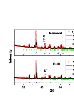
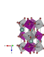
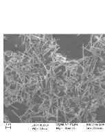
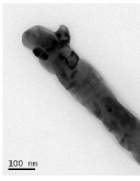
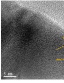
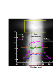
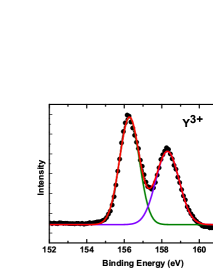
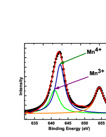
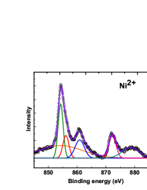
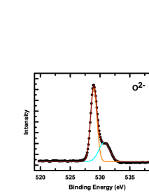
The Figure 1 shows the room temperature x-ray diffraction patterns for bulk and nanorods of YNMO and their refinement by FullProf. The crystallographic structure is also shown in Fig. 1. The crystallographic structure is found to be monoclinic (space group ) for both bulk and nanoscale samples though the nanorods appear to be oriented with (13) plane. It indicates a certain extent of texturing of the entire nanorod assembly on which the x-ray diffraction pattern was recorded. The lattice parameters were estimated to be = 5.221 Å, = 5.553 Å, = 7.479 Å, = 89.87o, and = 5.241 Å, = 5.583 Å, = 7.488 Å, = 89.87o, respectively, for bulk and nanoscale samples. Other crystallographic details such as ion positions, bond lengths and angles for both the bulk and nanoscale samples as well as the estimated standard deviation (corresponding to the lattice parameters and ion positions) and the fit statistics of the XRD data are included in the Supplemental Material Supplemental . The preferential orientation of (13) plane could be observed in high resolution transmission electron microscopy (HRTEM) images as well (Fig. 2). The HRTEM images were analyzed by using fast fourier transformation (FFT) and its inverse (IFFT) in order to identify the lattice planes and vectors clearly. In the Supplemental Material Supplemental , the HRTEM images and their FFT and IFFT versions are shown. The lattice planes and vectors have also been shown. The growth axis [13] of the nanorods could be observed in the images (Supplementary Materials). The SEM and bright field TEM images are shown in Fig. 2. The diameter of the nanorods is found to be around 100 nm. We further carried out detailed energy dispersive X-ray (EDX) elemental line profile analysis across the diameter of an individual nanorod by using scanning TEM (STEM) high angle annular dark field (HAADF) technique inside TEM. The Figure 2(d) shows the HAADF image of the nanorod as well as a profile of elemental concentration of Y, Mn, Ni, and O across the diameter of the nanorod. Clearly, while all the other elements are found to be homogeneously distributed across the entire diameter of the nanorod, concentration of oxygen was found to be decreasing near and across the surface region. The profile of oxygen concentration across the diameter of the nanorod yields the thickness of the region to be 10 nm where oxygen vacancies form. We, therefore, divide the whole nanorod into two regions - ‘stoichiometric’ and ‘nonstoichiometric’ - as shown in Fig. 2(d). Using this information, it is possible to estimate the total number of unit cells within the ‘nonstoichiometric’ region of a typical nanorod across which oxygen vacancies form. Considering the typical dimensions of the nanorod to be length 600 nm and diameter 100 nm and using the volume of the crystallographic cell (0.21913 nm3), the total number of unit cells in the whole of the nanorod is estimated to be 21504992. Since, the thickness of the ‘nonstoichiometric’ region is 10 nm, the number of the unit cells within the ‘stoichiometric’ region of the nanorod turns out to be 13763195. The number of cells within the ‘nonstoichiometric’ region is 36%. This is a siginificantly large number and, therefore, emergence of multiferroicity in this region should have profound impact. In order to corroborate the data of oxygen vacancy formation at the surface of the nanorods, we have also carried out the XPS. The spectra for Y, Mn, Ni, and O are shown in Fig. 3. The overall spectra were deconvoluted to obtain the main and sattelite peaks for each of the ions. For example, Fig. 3(a) shows the peaks at 156.5 eV and 158.5 eV for Y3+ states. The Figure 3(b) shows the deconvoluted peaks - main and satellite - for Ni2+. In both these cases, fitting of the spectra following background subtraction yields the charge states to be unique - i.e., Y3+ and Ni2+. Interestingly, however, Mn ions appear to be in the mixed state. Fitting of the peaks show that both Mn3+ and Mn4+ charge states are present. The ratio of the area () under the corresponding peaks [/(] is calculated to be 0.3. From the spectra for O2-, the charge state of oxygen ion turns out to be -2. Because of oxygen deficiency in the surface region, the Mn4+ ions were found to be reduced to Mn3+ and thus, XPS data corroborate the observations made by TEM. It appears that 30% of the Mn ions assume Mn3+ state within a region consisting of 36% cells. The XPS data for the bulk sample are shown in the Supplemental Material Supplemental . All the peaks corresponding to Y3+, Ni2+, Mn4+, O2- ions are found to reflect unique charge states. Signature of the presence of mixed charged state could not be observed in this case. This observation is consistent with those made by others for bulk YNMO Su . Only in nanoscale samples, Mn3+ arises because of oxygen vacancies near the surface region.
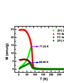
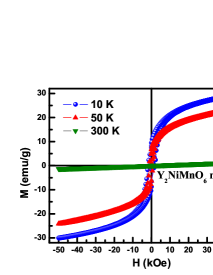
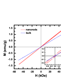
We now turn our attention to the results of magnetic property measurements. The zero-field-cooled (ZFC) and field-cooled (FC) magnetization versus temperature data are shown in Fig. 4(a) for both the bulk and nanoscale YNMO. While bulk sample exhibits the antiferromagnetic transition at 77 K, as expected, in the nanoscale samples, the is found to have dropped to 66 K. This is consistent with the observations made in other nanoscale magnetic compounds Zhao . Interestingly, within this size range, the nanorods appear to retain the long-range magnetic order (albeit with weaker strength) in the bulk of the sample. The Figures 4(b) and (c) show, respectively, the magnetic hysteresis loops across 50 kOe for nanoscale YMNO at different temperatures across 10-300 K and those for both bulk and nanoscale samples at 300 K. Clearly, the bulk sample exhibits linear i.e., paramagnetic pattern at 300 K. In contrast, the nanoscale sample exhibits finite magnetic coercivity [Fig. 4(c) inset] and very weak nonlinearity because of subtle surface magnetism. Using Brillouin function for the nonlinear ferromagnetic component and linear function for the paramagnetic one, we extracted the ferromagnetic component of the overall magnetization observed experimentally [Fig. 4(d)]. It yields the saturation magnetization to be 0.005 emu/g at room temperature. This turns out to be 5% of the maximum ferromagnetic moment expected for perfect ‘ferro’ alignment of all the spins in YNMO. Near linearity in also signifies presence of long-range antiferromagnetic order in the surface region. The coercive fields for forward and reverse branches turn out to be 735 Oe and 600 Oe, respectively. This yields the cocercivity 666 Oe and exchange bias field 67.5 Oe. Finite confirms presence of surface antiferromagnetism and interface between ferromagnetic and antiferromagnetic regions. The shape of the hysteresis loop, though appears to be unusual, resembles closely the one expected of a dilute assembly of noninteracting three-dimensional nanoparticles with higher packing density Usov .
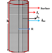

To examine the origin of magnetic coercivity of the assembled nanorods we consider that the surface of the nanorods are ferromagnetic in nature. We model the rod-like nanoparticles as cylinders of radius and height [as shown in Fig. 5(a)] consisting of classical Heisenberg spins arranged in a cubic lattice Sahoo , i.e., there are spins along the diameter of the cylinder; such identical nanorods are assembled randomly to form the superstructure as shown in Fig. 5(b) which mimics the self-assembled nanorods observed in our experiments. For comparison, we also consider two other kind of assmbled structures by attaching the rods as end to end and side by side, which is shown in the Supplemental Material Supplemental .
Each lattice site of the superstructure is associated with a classical Heisenberg spin ; we denote the lattice sites in the bulk by a set B and those on the surface by a set S. These spins interact following the Hamiltonian,
| (2) | |||||
where is the nearest neighbor of site , , () are the exchange interaction strength among the spins within the bulk B (surface S); represents interaction between spins in the bulk and the surface. The external magnetic field is applied along the easy-axis, which is chosen as the -direction. To model a paramagnetic core (bulk) and ferro or antiferromagnetic surface we set to be very small and can take positive or negative values depending on whether the surface is ferro or antiferromagnetic, respectively.
We study the hysteresis properties of these nanoparticle super-structures using Monte Carlo simulations with a single spin-flip Metropolis algorithm where a trial configuration is accepted with probability . Here, is energy difference between the present configuration and the trial one. The trial configuration is constructed by changing the angles of a randomly chosen spin by a small but random amount.
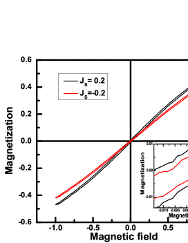
To calculate the hysteresis of the self-assembled nanorods we consider rods arranged randomly, as shown in Fig. 5(b). The radius and the height of the nanorods are taken as and lattice units respectively. The interaction parameters of the Hamiltonian are set as follows. For the paramagnetic core and ferro or antiferromagnetic surface, we set and consider in the range ; is expected to be similar in magnitude as that of and we set . The temperature of the system is set as , which is much smaller than the critical temperature of the system; such a state with can be achieved in the Monte Carlo simulation, starting from any random initial configuration, by relaxing the system in zero-field-cooled condition for a long time. Then, the magnetic field is raised slowly from to with a field sweep rate units per Monte Carlo sweep (MCS) and finally, the hysteresis loop calculations are undertaken for a cycle by varying the field from to and then to . To this end we take and = , i.e., the magnetic field is raised from to in 500 MCS.
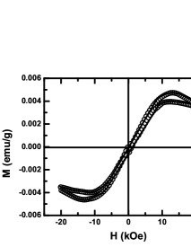
We have calculated the hysteresis loop for different ; the magnetization loop for , shown in Fig. 5(c), has linear behaviour and a small coercive field, which compares well with our experimental data. This perhaps confirm the presence of ferromagnetic ordering at the surface of the self-assembled nanorods along with a paramagnetic ordering in the bulk. For comparison, we, in Fig. 5(c), have also shown the hysteresis loop for , where the surface has a antiferromagnetic order. Higher coercivity [Fig. 5(c)] for = 0.2 corroborates the experimental result. It proves presence of surface ferromagnetism in the present case.
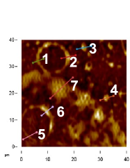
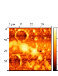
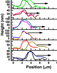
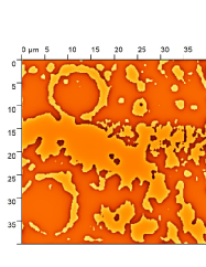
The room temperature surface ferromagnetism is probed further by magnetic force microscopy (MFM). We show, respectively, in Figs. 6(a) and 6(b) the topography and MFM phase contrast images of nanorods of YNMO dispersed within ethanol and deposited on SiO2/Si substrate. The sample was kept under 1000 Oe field prior to the measurements. The particles, as a result, appear to organize themselves in the form of rings via, possibly, magnetic interactions. The line profile data corresponding to the topography and phase contrast images are shown in Fig. 6(c). The phase contrast image [Fig. 6(b)] is also analyzed by using Gwyddion software for mapping the distribution of stray field. The details of the analysis is described in the Supplemental Material Supplemental (see also the reference [S1] therein). The distribution of the stray field is shown in Fig. 6(d). The line profile data corresponding to the phase contrast MFM image have, in fact, been generated from this analysis. The comparison of the line scan data for topography and phase contrast images shows how the perpendicular stray field extends across the cluster of nanorods in different zones of the area under focus. From this, it appears that the magnetic domains extend across the individual nanorods and correspond closely to the respective cluster size as observed in many such magnetic nanoparticle assemblies Puntes . All these information confirm the presence of weak yet finite surface ferromagnetism as paramagnetic strucure would not have resulted in such stray field distribution across the particle surface. The observation of long-range magnetic order and oxygen deficiency within the surface region, therefore, points out that Ni-O-Mn-O-Mn pathway is responsible for developing the exchange coupling interactions in the surface. We next examine the exchange coupling interaction in detail. The surface ferromagnetism, in many oxide perovskite systems, was shown Aliyu to result from double exchange interactions involving mobile charge carriers arising from oxygen deficiency at the surface. Identification of the appropriate exchange interaction pathway is important. For single transition metal ion systems, it is straightforward. However, for systems involving more than one transition metal ion, as in our case, the exchange interaction pathway could be complex and, therefore, the mechanism too could be more involved. In the bulk YNMO, the exchange coupling interactions across Ni2+-O2--Ni2+, Mn4+-O2--Mn4+, and Ni2+-O2--Mn4+ bonds were found to be responsible to yield E-type antiferromagnetic structure below 70 K. In the case of nanorods, because of the presence of Mn3+ ions at the surface, exchange coupling interactions across Ni2+-O2--Mn3+, Mn3+-O2--Mn3+, Mn3+-O2--Mn4+ bonds yield the surface magnetism at room temperature. Within the surface crystallographic structure (which because of its lower dimension and consequent noncentrosymmetry could yield large Rashba spin-orbit coupling), the DM exchange across Mn3+-O2--Mn3+ could stabilize.
It is, of course, important to mention here that the symmetry breaking magnetic structure could emerge either due to Dzyaloshinskii-Moriya (DM) antisymmetric exchange coupling interaction among the noncollinear spins or from exchange striction interaction among the collinear spins Nagaosa . The spin-orbit coupling assumes immense importance in the former case but not in the latter. The theoretical and experimental work, carried out so far Fert , have, of course, shown quite convincingly that the lower dimensional structures - such as surface and interface regions - or artificially constructed two-dimensional layers exhibit stabilization of noncollinear spin structures with DM exchange interaction. The role of Rashba spin-orbit coupling has been examined in such lower-dimensional structure in detail Fert . Symmetric “exchange striction” interaction may not be quite relevant in such systems. Direct experimental proof Gross ; Chaurasiya of prevalence of DM exchange interaction in the cases of surface/interface magnetism has also been provided. Since, in the present case, we observe ferroelectricity originating from surface magnetism at room temperature (where bulk magnetism has no role to play), it is quite likely that the surface magnetism in this case of Y2NiMnO6 nanorods involves noncollinear spin structure. Therefore, ferroelectricity here should be originating from the antisymmetric DM exchange coupling interaction (involving large Rashba spin-orbit coupling) confined within the lower dimensional surface region of the nanorods identified by the TEM experiments. The exchange striction interaction may not play any significant role here. This issue will be taken up further by using first-principles calculations separately.
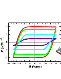
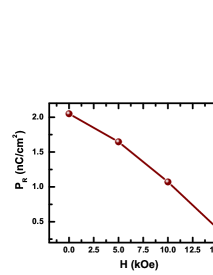
We finally measured the remanent ferroelectric hysteresis loops at room temperature under different magnetic fields 0, 5, 10, and 15 kOe [Fig. 7(a)]. The loops have been measured by using an involved protocol which sends out fourteen voltage pulses to switch the domains and measure both the switchable and nonswitchable components of the polarization. Elimination of the contribution of nonswitchable component from the overall polarization yields the switchable remanent polarization. The details of the protocol and its underlying physics have been described in Ref. [28]. The loop shape is consistent with that observed by others for different ferroelectric compounds Scott . Interestingly, the remanent polarization is found to decrease by 80% under 15 kOe field at room temperature [Fig. 7(b)]. The Figure 7(a) inset shows the typical sample and electrode configuration. The decrease in under 0-15 kOe field indicates strong magnetoelectric coupling in nanorods of YNMO at room temperature. Such strong coupling is expected in cases where ferroelectricity originates from magnetism and the magnetic structure - including the magnetic anisotropy - changes under a magnetic field. Because of lower dimension at the surface, large Rashba spin-orbit coupling is expected Fert which, in turn, could stabilize the DM exchange interaction across Mn3+-O2--Mn3+ among the other possible superexchange and double exchange interactions. Distinct magnetic structure at the surface has earlier been observed in other systems as well Langridge . Since the surface ferroelectricity originates here from the magnetic structure, because of change in the magnetic anisotropy and/or structure under field, ferroelectric polarization too should change. It turns out that the change in the magnetic structure and/or switch in anisotropy (quantified by switch or rotation of the DM vector) under field in individual nanorod leads to decrease in overall polarization when summed up over the entire ensemble of nanorods studied. Of course, more detailed experimental as well as theoretical work needs to be done to unravel the surface magnetic structure and its change under such moderate magnetic field 0-15 kOe at room temperature. The interesting results presented in this paper on nanorods of double perovskite Y2NiMnO6 should trigger deeper investigation.
IV Summary
In summary, we observed surface multiferroicity - magnetism, ferroelectricity, and significantly large magnetoelectric coupling - at room temperature in nanorods of double perovskite Y2NiMnO6 compound where bulk multiferroicity is observed only below 70 K. The surface magnetism has been probed by global magnetic measurements as well as imaging by magnetic force microscopy. It is found to be comprised of both ferromagnetic as well as antiferromagnetic domains. The Dzyloshinskii-Moriya exchange coupling interaction appears to stabilize and yield finite remanent ferroelectric polarization. Large magnetoelectric coupling, observed in this system, should trigger fresh research on other such candidate nanosized compounds for opening a new pathway of inducing room temperature surface multiferroicity even if its bulk counterpart either does not exist or exists only at low temperature.
ACKNOWLEDGMENTS
Two of the authors (S.M. and A.S.) acknowledge support (INSPIRE fellowship) from the Department of Science and Technology, Government of India, during this work.
References
- (1) M. Fiebig, T. Lottermoser, D. Meier, and M. Trassin, Nat. Rev. Mater. 1, 16046 (2016).
- (2) I. Zutic, A. Matos-Abiague, B. Scharf, H. Dery, and K. Belaschenko, Materials Today 22, 85 (2019).
- (3) N.A. Spaldin and R. Ramesh, Nat. Mater. 18, 203 (2019).
- (4) J. Fontcuberta, V. Skumryev, V. Laukhin, X. Granados, and E.K.H. Salje, Scientific Reports 5, 13784 (2015).
- (5) Y. Yang, H. Xiang, H. Zhao, A. Stroppa, J. Zhang, S. Cao, J. Iniguez, L. Bellaiche, and W. Ren, Phys. Rev. B 96, 104431 (2017).
- (6) See, for example, N. Mathur, M.J. Stolt, and S. Jin, APL Mater. 7, 120703 (2019).
- (7) S. Seki, X.Z. Yu, S. Ishiwata, and Y. Tokura, Science 336, 198 (2012).
- (8) E. Ruff, S. Widmann, P. Lunkenheimer, V. Tsurkan, S. Bordacs, I. Kezsmarki, and A. Loidl, Science Advances 1, e1500916 (2015).
- (9) I. Kezsmarki, S. Bordacs, P. Milde, E. Neuber, L.M. Eng, J.S. White, H.M. Ronnow, C.D. Dewhurst, M. Mochizuki, K. Yanai et al., Nat. Mater. 14, 1116 (2015).
- (10) Y. Nahas, S. Prokhorenko, L. Louis, Z. Gui, I. Kornev, and L. Bellaiche, Nat. Commun. 6, 8542 (2015).
- (11) L. Wang, Q. Feng, Y. Kim, R. Kim, K.H. Lee, S.D. Pollard, Y.J. Shin, H. Zhou, W. Peng, D. Lee et al., Nat. Mater. 17, 1087 (2018).
- (12) M.A.P. Goncalves, C. Escorihuela-Sayalero, P. Garca-Fernandez, J. Junquera, and J. Iniguez, Science Advances 5, eaau7023 (2019).
- (13) S. Das, Y.L. Tang, Z. Hong, M.A.P. Goncalves, M.R. McCarter, C. Klewe, K.X. Nguyen, F. Gomez-Ortiz, P. Shafer, E. Arenholtz et al., Nature (London) 568, 368 (2019).
- (14) See, for example, A. Soumyanarayanan, N. Reyren, A. Fert, and C. Panagopoulas, Nature (London) 539, 509 (2016).
- (15) A.R. Tarkhany, M. Discacciati, and J.J. Betouras, Phys. Rev. B 103, 205409 (2021).
- (16) A. Sundaresan, R. Bhargavi, N. Rangarajan, U. Siddesh, and C.N.R. Rao, Phys. Rev. B 74, 161306(R) (2006).
- (17) C. Lu, W. Hu, Y. Tian, and T. Wu, Appl. Phys. Rev. 2, 021304 (2015).
- (18) J. Su, Z.Z. Yang, X.M. Lu, J.T. Zhang, L. Gu, C.J. Lu, Q.C. Li, J.-M. Liu, and J.S. Zhu, ACS Appl. Mater. Interfaces 7, 13260 (2015).
- (19) See the Supplemental Material for the structural details of the bulk and nanorods of Y2NiMnO6, high resolution transmission electron microscopy images and their analyses, x-ray photoelectron spectroscopy data for the bulk sample, results of Monte-Carlo simulation for different types of assembled nanorods, and the details of the analyses of magnetic force microscopy images. It is available on request from the corresponding authors.
- (20) See, for example, J. Wang, W. Wu, F. Zhao, and G.-M. Zhao, Appl. Phys. Lett. 98, 083107 (2011).
- (21) See, for example, N.A. Usov, O.N. Serebryakova, and V.P. Tarasov, Nanoscale Research Letters 12, 489 (2017).
- (22) A. Sahoo, D. Bhattacharya, and P.K. Mohanty, Phys. Rev. B 101, 064414 (2020).
- (23) V.F. Puntes, P. Gorostiza, D.M. Aruguete, N.G. Bastus, and A.P. Alivisatos, Nat. Mater. 3, 263 (2004).
- (24) H.D. Aliyu, J.M. Alonso, P. de la Presa, W.E. Pottker, B. Ita, M. Garcia-Hernandez, and A. Hernando, Chem. Mater. 30, 7138 (2018).
- (25) See, for example, Y. Tokura, S. Seki, and N. Nagaosa, Rep. Prog. Phys. 77, 076501 (2014).
- (26) I. Gross, L.J. Martinez, J.-P. Tetienne, T. Hingant, J.-F. Roch, K. Garcia, R. Soucaille, J.P. Adam, J.-V. Kim, S. Rohart et al., Phys. Rev. B 94, 064413 (2016).
- (27) A.K. Chaurasiya, A. Kumar, R. Gupta, S. Chaudhary, P.K. Muduli, and A. Barman, Phys. Rev. B 99, 035402 (2019).
- (28) U. Chowdhury, S. Goswami, D. Bhattacharya, A. Midya, and P. Mandal, Appl. Phys. Lett. 109, 092902 (2016).
- (29) J. Gardner and J.F. Scott, Materials Today 21, 553 (2018).
- (30) S. Langridge, G.M. Watson, D. Gibbs, J.J. Betouras, N.I. Gidopoulos, F. Pollmann, M.W. Long, C. Vettier, and G.H. Lander, Phys. Rev. Lett. 112, 167201 (2014).