Silicon Pore Optics
Abstract
Silicon Pore Optics (SPO) uses commercially available monocrystalline double-sided super-polished silicon wafers as a basis to produce mirrors that form lightweight high-resolution X-ray optics. The technology has been invented by cosine Measurement Systems and the European Space Agency (ESA) and developed together with scientific and industrial partners to mass production levels. It leverages techniques and processes developed over decades by the semiconductor industry to handle, process, and clean silicon wafers and plates. SPO is an enabling technology for large space-borne X-ray telescopes such as Athena and ARCUS, operating in the 0.2 to 12 keV band, with angular resolution aiming for 5 arc seconds. SPO has also shown to be a versatile technology that can be further developed for gamma-ray optics, medical applications and for material research.
1 Keywords
X-ray optics, X-ray telescope, Athena, Wolter I, monocrystaline silicon, silicon wafer, mass production
2 Introduction
The launch of the high-energy astrophysics observatories XMM-Newton jansen.2001vn and Chandra Weisskopf:2002wb in 1999 marked the culmination of two major optics development efforts, and made observations of the X-ray sky with unprecedented sensitivity possible. Significant investments were required, and two different optics technologies had to be developed to make these missions possible. The optics of XMM-Newton are based on electro-formed nickel, replicated from precision mandrels. They maximise effective area to make high-resolution spectroscopy of distant sources possible Gondoin:1994wo . The Chandra optics, on the other hand, optimise the angular resolution at the cost of mass and effective area to provide high-resolution imaging. After more than two decades of active operations, these two missions remain in high demand for their stand-alone capabilities and the synergies with observations at other wavelengths. Their systems are however ageing, and the need for higher performance continues to increase.
The next generation high-energy astrophysics observatory will have to reach deeper into the Universe, keeping pace with the present and future ground and space based observatories like the James Webb Space Telescope (JWST), the Square Kilometer Array (SKA), and the Extremely Large Telescope (ELT). More photons will have to be collected from very distant sources, requiring larger effective area, good angular resolution to avoid source confusion, and more sophisticated detector instruments.
In 2014, the European Space Agency (ESA) selected the Advanced Telescope for High-ENergy Astrophysics (Athena) as the second large-class mission designed to address the Cosmic Vision science theme ’The Hot and Energetic Universe’ Nandra:2013ue . This X-ray space telescope will rely on a novel type of optics, which was specifically invented and developed to enable large area telescopes with few-arc-second resolution: the Silicon Pore Optics (SPO) Bavdaz2005 ; Beijersbergen:2004vc .
The challenge of the Athena optics is the need to simultaneously comply with three technical requirements:
-
•
Provide a large effective area (1.4 m2 at 1 keV),
-
•
Provide a good angular resolution (5 arcsec HEW),
-
•
Remain in the mass allocation (around 1000 kg).
XMM-Newton and Chandra required different optics technologies, because they had to deliver different combinations of these three parameters. This is true also for the other X-ray missions flown to date, from Exosat de-Korte:1981ts , Einstein van-Speybroeck:1979wp , ASCA Serlemitsos:1995ti and Rosat Truemper:1982uu , to BeppoSAX Conti:1994uc , Hitomi (Astro-H) Okajima:2016ts , NuSTAR Harrison:2013wl , and eRosita Merloni:2012ug . The optics for each of these missions are an engineering masterpiece, each requiring substantial effort, skill, time, and funding to be developed and flown.
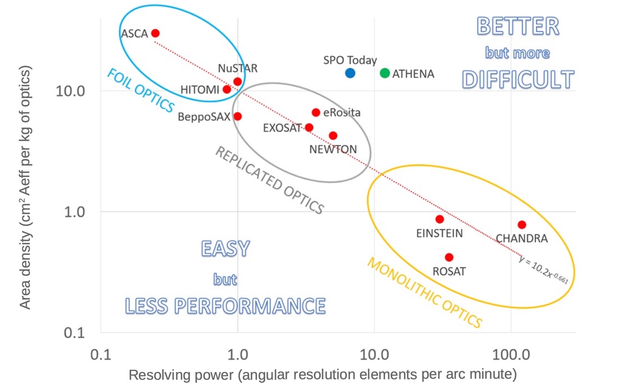
In Figure 1 the optics of these missions are compared, considering the aforementioned three parameters. The area density of the respective optics, expressed as effective area per mass of the optics is plotted against the resolving power of the optics, expressed as angular resolution elements per arcminute Bavdaz_SPIE_2021 . A clear correlation is observed despite the fact that the optics technologies are very different, ranging from foil-based optics to replicated optics and monolithic optics. Each of these systems was developed and built with large effort, and each represents a major achievement, but they all follow a power law correlation. Even the Chandra optics, which are the result of extraordinary efforts in engineering and funding, manage to move only very slightly to the upper right side of the correlation line. The same is true for eRosita, which represents the highly optimised third generation of electroformed nickel technology.
The graph illustrates that lightweight optics with large effective area but lower angular resolution, or high resolution but heavy optics with a limited effective area have been built until now. Current optics-making technologies have so far allowed for the production of systems where only two of the three parameters can be effectively optimized at one time. The optics for the Athena mission (green dot in Figure 1) however require a technological change to move away from this empirical power law into the ‘difficult corner’ to the upper right of the graph. Linear extrapolation of all the X-ray missions flown to date using the three previous conventional technologies suggests that it would be possible to deliver the resolution and effective area, but it would require a mass of about 7000 kg, which is the mass of the complete Athena mission. Or it could respect the mass allocation of 1000 kg and deliver the effective area, but with a severely degraded angular resolution of about 1.6 arcminutes.
In this chapter we describe the status of SPO, an X-ray optics technology developed to make it possible to build a system that departs from the empirical power law defined by existing technologies, and make missions like Athena possible. The SPO technology has already demonstrated the compliance with the Athena effective area and mass requirements. The angular resolution is approaching the Athena requirement as well, being already one order of magnitude better than what the established technologies could deliver for the same mass and effective area, and it has been continuously improving over the past 10 years (e.g. Collon:2011tx ; Collon:2013tj ; Collon:2015wv ; Collon:2017vj ; Collon:2019ww ; Collon:2021tk ). This technology will undoubtedly also find other applications in demanding future space missions (the ARCUS mission studied by NASA is an example Randall_SPIE ) and ground-based applications, extending from opportunities in medicine Girou_2021 to material testing and security applications.
We introduce the SPO technology, its potential, and how it is currently realized in the first part of the chapter. Although the development of SPO is driven by Athena, we purposely keep the description of the concept and technology as general as possible. In the second part, we discuss more specifically the optics for Athena with its current design and performance estimates.
3 SPO concept
SPO technology uses commercially available monocrystalline double-sided super-polished silicon wafers as a basis to produce X-ray mirrors. In addition to its direct bonding property Shimbo1986 ; Maszara1988 , silicon is rigid, has a relatively low density, and a very good thermal conductivity. Silicon wafers have excellent surface finish, both in terms of figure and surface roughness, making them a superb base material to build X-ray mirrors.
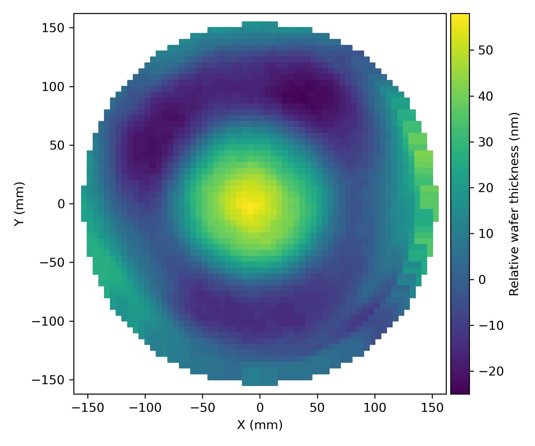
SPO development leverages the massive investments done in the semiconductor and automotive industries, which made available high-performance equipment, tools, materials and processes allowing high-quality mass production. The work-horse of the semi-conductor industry are thin 300-mm wafers sawn out of monocrystalline ingots, grown from poly-crystalline silicon using the Czochralski method. These wafers are produced with outstanding quality for a modest cost: prime grade double-sided super-polished monocrystalline 300 mm silicon wafers have specifications of 0.1 nm root mean square (RMS) surface roughness and total thickness variation (TTV) of less than 0.2 m Landgraf:2019uz (see Figure 2).
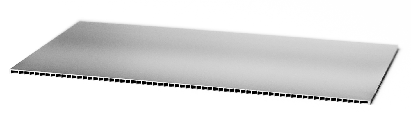
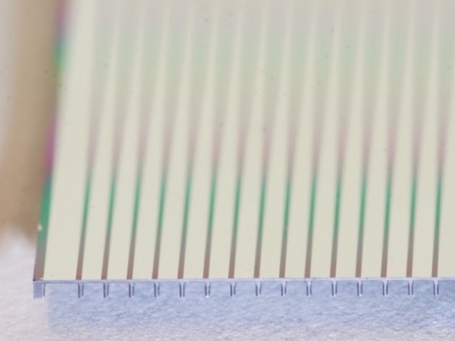
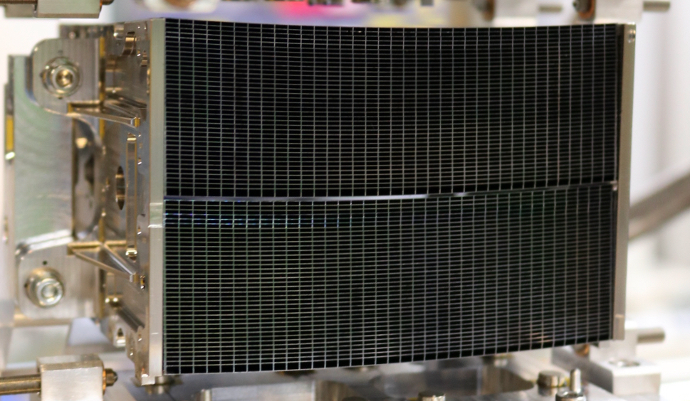
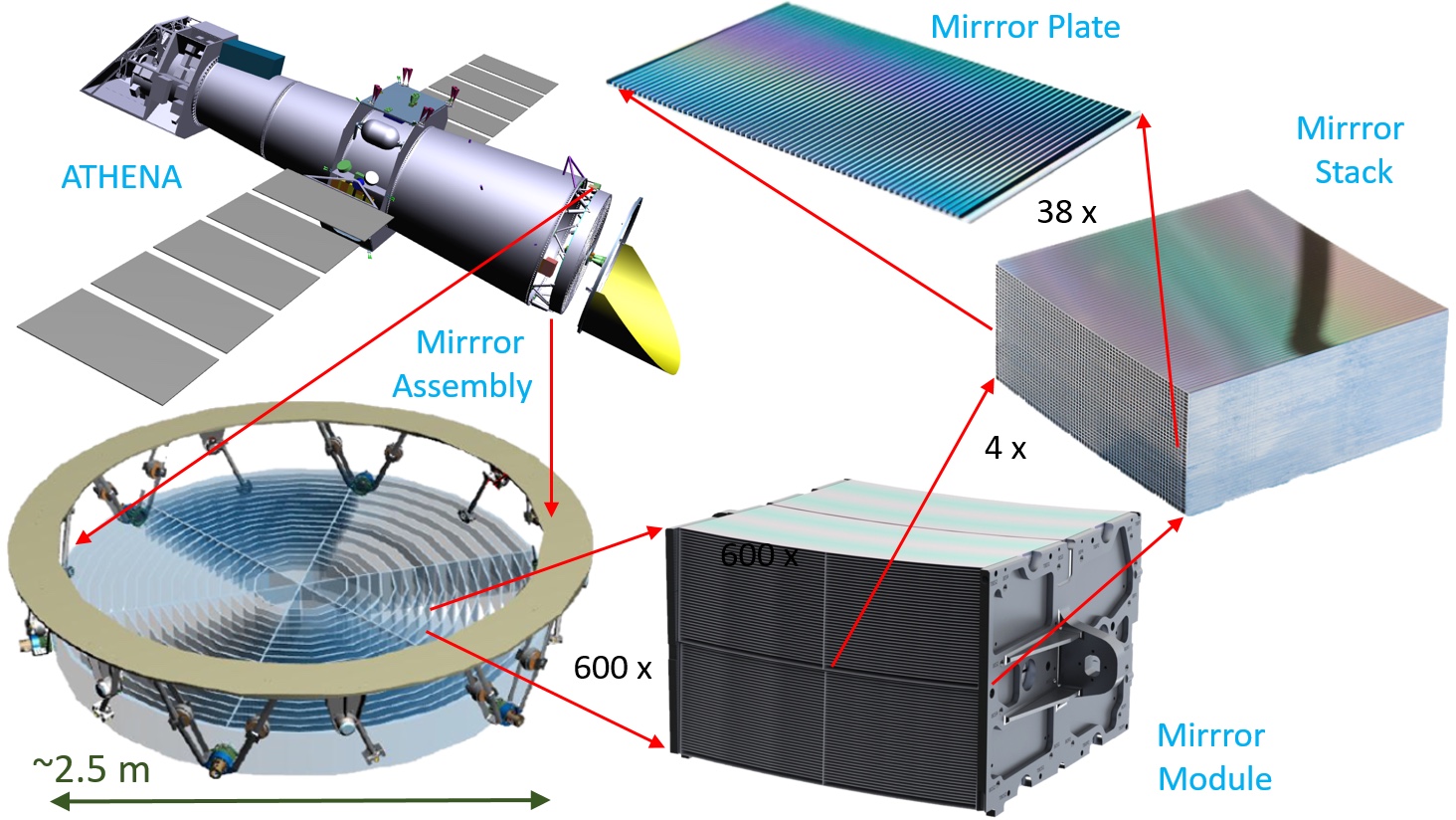
SPO substrates, also called mirror plates or simply plates, are cut out of wafers and carved out on one side in a regular pattern to leave thin parallel walls called ribs. In other words, plates consist of a thin membrane with a smooth reflective surface on one side and ribs along the plate length on the other. Plates are stacked to form a lightweight and stiff structure with a large number of rectangular pores that allow X-ray photons to be reflected: hence the name silicon pore optics.
The plates are bonded on top of each other thanks to direct silicon bonding, which requires no adhesives. Starting from a mandrel that defines the optical design, plates are stacked and the mandrel figure is preserved owing to the plan-planarity of the mirror plates and the lack of any adhesive between plates. It results from the process a self-supporting stack of elastically deformed mirror plates that reproduce the shape of the mandrel. In such a stack, X-ray photons enter pores at low-grazing angles, are reflected on the reflective side of each plate, and exit the optics at the opposite end. These stacks consistute lightweight, moderate-to-high resolution, X-ray optics (see Figure 3).
Typical X-ray focusing optics use nested shells to fill the available aperture and maximize effective area because low grazing incidence angles are needed for X-ray reflections. Because the ribs act as spacers between mirror plates, SPO can achieve an extremely high packing density of shells. The stiffness obtained by the bonded plates makes it possible to reduce the thickness of the membranes without impacting the figure accuracy, in a lightweight structure leading to large open area ratio.
SPO can be made to comply to many optical geometries, with the Wolter I Wolter:1952vf configuration being in general the most attractive for high-energy astrophysics applications. Two reflections are required to form an imaging system at grazing angles of incidence, and this is achieved by placing two stacks, a primary and a secondary, in series along the path of the incoming photons. Two brackets, to which the stacks are bonded, are used to fix the relative orientation of the primary and the secondary, and they provide a mechanical interface for integration in a larger structure.

3.1 Potential and limitations of SPO
In this section, we discuss the potential and limitations of the SPO technology in general terms. For Wolter I geometry, three aspects are discussed: the plate minimum and maximum lengths, the radial spacing between mirror plates, and the smallest sagittal radius that can be achieved.
The maximum dimensions of a plate are constrained by the size of the wafer that is used. Standard silicon wafers come in diameters ranging from 50 to 300 mm, with thickness increasing from 275 m to 775 m, respectively. At present, the semiconductor industry is widely making use of 300 mm diameter wafers. Larger wafers with 450 mm diameter and 925 m thickness have been discussed for many years, but are not yet widespread due to the significant investments needed to transition mass-processing facilities and tools from 300 mm to 450 mm. Therefore, at present, SPO mirror plates are limited to lengths shorter than 300 mm. At the other end of the range, although there is no clear minimum, it would become difficult to handle plates shorter than 10 mm.
The pore height , which is related to the plate length by equation 1 where is the incidence angle, can be decreased by using smaller and hence thinner wafers.
| (1) |
Thinner wafers are produced in smaller series and present higher roughness and larger thickness variations than the standard 300 mm ones, which has until recently made them less attractive to use. However, some of these defects can be eliminated with the use of ion beam figuring (IBF), which now offers a way to reduce thickness variations and reduce roughness (see Section 4.1). Thus, it is possible to think of SPO with mirror plate pitch smaller than 0.775 mm. At the other end, it would also be possible to bond wafers together and then process them. This opens the possibility to create stacks of mirror plates with double-pitch of 1.55 mm. This would be useful in case of large incidence angle, where the plate length would become too short otherwise.
SPO stacks replicate the shape of the mandrel, whether it is flat, cylindrical or conical. It can also feature a meridional curvature, parabolic, hyperbolic, circular, or any other shape. The minimum radius of sagittal curvature is only linked to the material properties, and in turn to the membrane thickness. Membrane thickness of 100 m has been tested successfully, while 110 m has been manufactured routinely for Athena. With these thicknesses the plates can be bent to about 150 mm diameter while remaining comfortably far from critical stress that would lead to breakage.
The width and spacing of the ribs determine the open area ratio of the optics, affecting on-axis effective area and vignetting. These parameters also affect the final stiffness of the system, and have impact on the optical performance. The higher the density of ribs, the smaller the open area ratio, the stronger the support of the mirror membrane.
SPO can also be used to manufacture medium to large series of other type of optics, where only the top plate is reflective, and the lower plates are structural to maintain the shape. This can be used, for instance, for Kirckpatrick-Baez optics 1948JOSA…38..766K . SPO technology has also the potential to create advanced gamma-ray focusing elements via the use of diffraction in the volume of the crystalline plates. Self-standing single or double-curvature stacks of plates can be used as Laue lens elements providing improved focusing capability compared to other methods Girou_2021 .
4 SPO realization
4.1 Production of SPO mirror plates
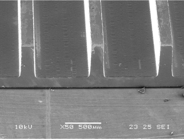
With the technology contributions from the semiconductor industry, mass production is being set up and standardized processes are being developed in order to manufacture SPO mirror plates in high quality, large quantity, and at relatively low cost Landgraf:2019uz ; Landgraf:2021tf The production of SPO mirror plates starts with carving out ribs into 300 mm wafers. This process is effectively performed by removing material from the wafer down to the desired membrane thickness. Subsequently, rectangular plates are diced off the wafer, with the ribs along the direction of travel of the X-rays. The orientation of plate ribs and edges is aligned with a crystal plane of the silicon to ensure correct bending, as well as chemical processing properties of the material in subsequent production steps. The top side of the mirror plate is the reflective side (Figure 4, a)) and the bottom is the ribbed side (Figure 4 b)) with the ribs parallel to each other. The plates currently manufactured have rib pitch varying from 1.0 mm to 2.4 mm with rib width of 0.17 mm.
The SPO mirror plates feature a thickness gradient along the rib direction to ensure that all the plates within a stack are confocal (see section 5.2). The plane of the ribs is at an angle with the reflective side, referred to as the wedge angle. The challenge is to implement this angle with a linear profile, and without increasing the roughness of the surfaces. Two approaches have been developed to realize the wedge angle. A thickness gradient is either created by wet-chemical etching, or by IBF. A wedge accuracy better than 1% ensures limited contribution to the optical quality budget Vacanti:2021wh . A wedge accuracy better than 1% has been obtained with the wet-chemical processing Landgraf:2021tf , while the IBF is still under development. The advantage of IBF is that the TTV of wafers can be improved and reduced to potentially less than 10 nm in the same production step as the wedge processing.
Cleanliness is a crucial parameter for the production stacks. Particles on the plate surface can reduce bonding area and distort the optical figure. For this reason, SPO mirror plate production is performed in high-quality clean room environments of ISO 6 and ISO 5, and with specific equipment reducing also the risk of organic contamination, which can have a negative impact on the bondability of SPO mirror plates.
4.2 Development of coatings
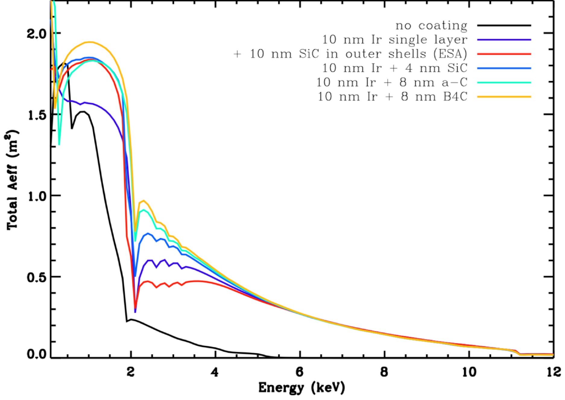
The reflectivity of SPO mirror plates can be enhanced by deposition of thin-film coatings. The effectiveness of the coating is thereby described by the effective area of the optics. It depends on the collecting area and the efficiency of the mirrors in reflecting high-energy photons. The broadest energy window can be achieved with combinations of high-Z (e.g. Au, W, Mo, Pt and Ir) and low-Z materials (e.g. Si, SiC, C, DLC and B4C). Figure 23 in Section 5.3.1 shows an example of the computed on-axis effective areas for different reflective coatings for the Athena telescope energy range. The effective area is significantly larger with the addition of high-Z/low-Z bilayer coatings compared to the effective area of un-coated SPO mirror plates. In addition, multilayer coatings, consisting of superimposed bilayers of high-Z/low-Z material, can be applied to further increase the X-ray response of the optics at higher energies 10.1117/1.JATIS.6.3.034005 .
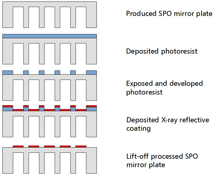
The SPO mirror plates feature a patterned coating on their reflective side in order to enable direct silicon bonding Shimbo1986 ; Maszara1988 (see Section 4.4). The patterning of the coating is performed via optical lithography. This process, sketched in Figure 5, consists of the following steps. Firstly, a photosensitive polymer is deposited on the reflective side of the SPO mirror plate. In a second step, a patterned photoresist layer is created by exposing the photosensitive polymer to ultraviolet light and developing it by immersing the sample in a chemical solution. Subsequently, an X-ray reflective coating is deposited using a sputtering deposition technique. Finally, chemical lift-off is performed to remove the coated photoresist resulting in a patterned coated SPO mirror plate.
Direct current magnetron sputter deposition (MSD) has been applied to produce X-ray reflective coatings on mirrors for a number of X-ray telescopes, and as such, is a method with a good track record. It is a low-cost and well-controlled process. Particularly, iridium films with a thickness of 30 nm have been sputtered onto the Chandra telescope mirrors Gorenstein2010 , and Pt/C and W/Si bilayer systems have been used for the NuSTAR telescope mirrors successfully 10.1117/12.894615 .
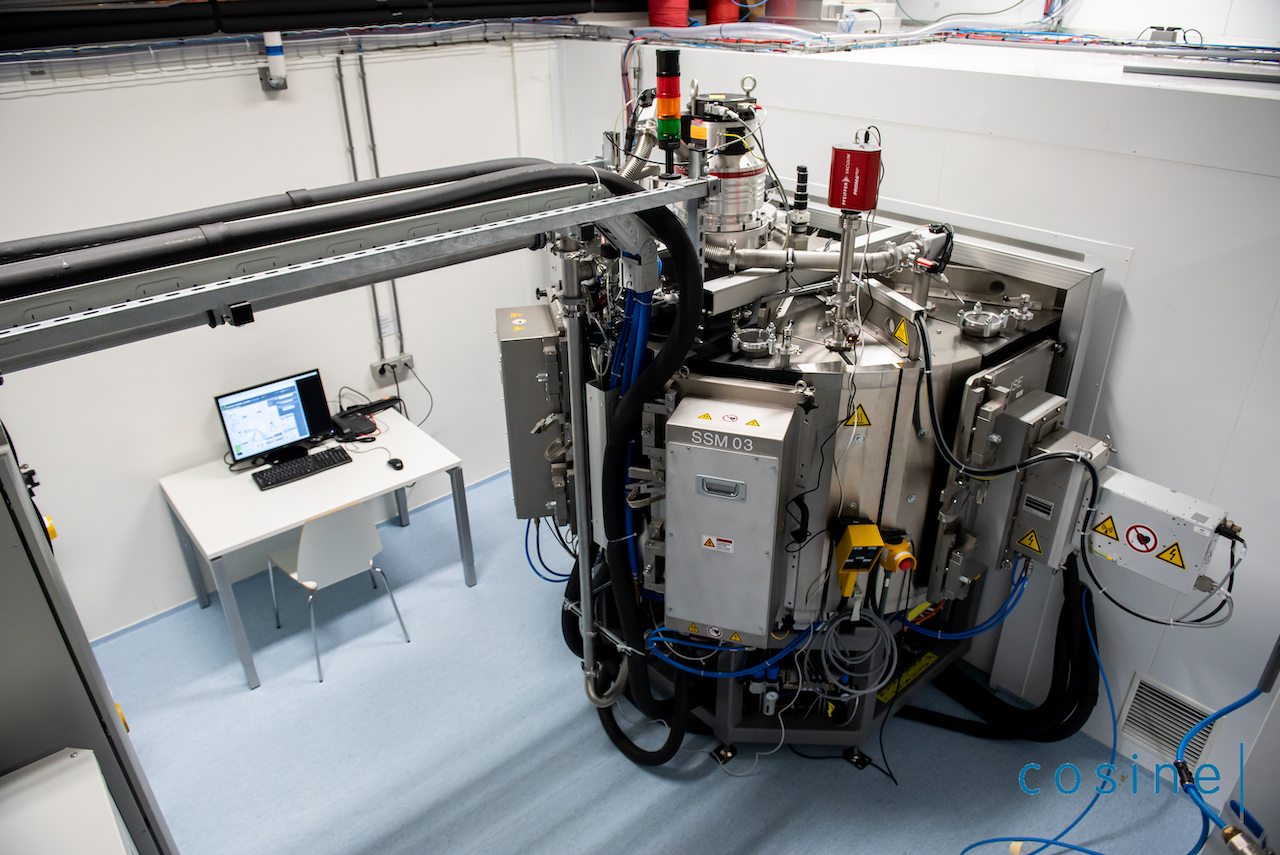
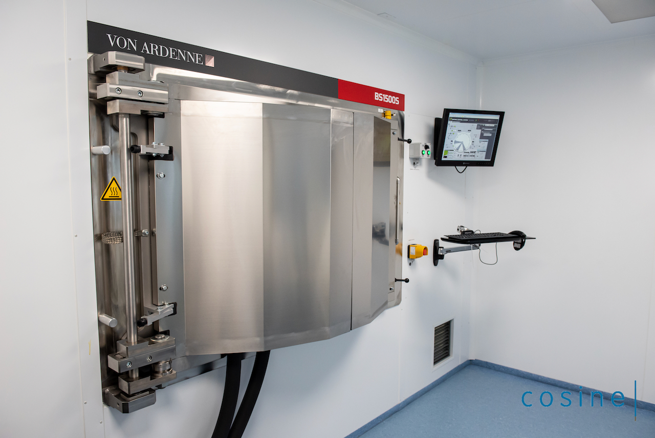
The SPO mirror plate coating process takes place at cosine using an industrial, high-throughput magnetron sputtering system 10.1117/12.2528351 (Figure 6). It features three magnetrons for coating target materials and a plasma cleaning system in order to clean substrates from organic materials before a coating deposition run Girou2020 . It is also possible to accommodate other types of deposition methods, such as thermoionic vacuum arc deposition that may be more suitable to improve the coating quality for particular materials. With this system, substrates as large as full 300 mm wafers can be coated with various high-Z materials such as tungsten, molybdenum, platinum and iridium and low-Z materials such as silicon, silicon carbide, carbon, diamond-like carbon, and boron carbide.
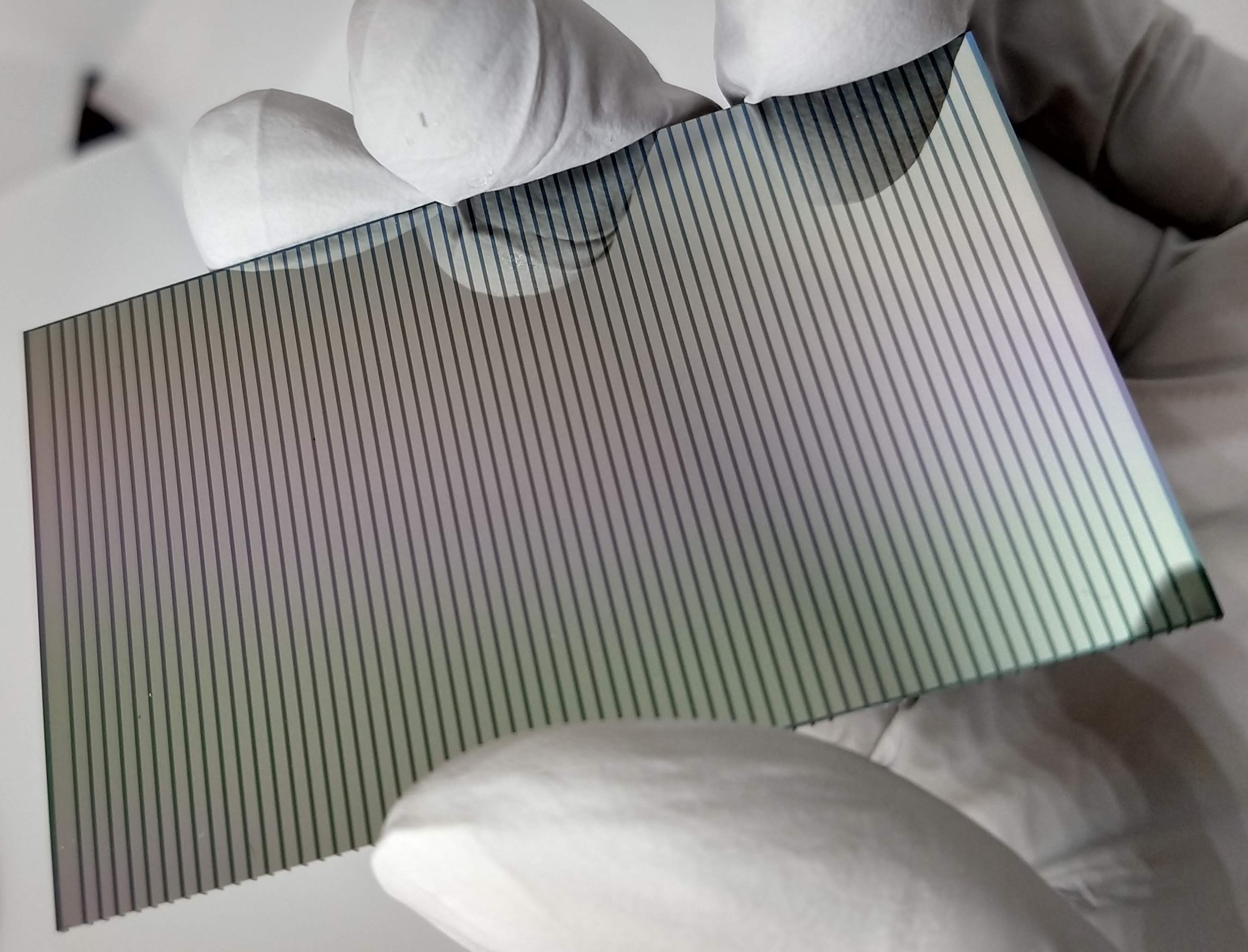
The left photograph in Figure 7 shows an example of the reflective side of a produced patterned iridium-coated SPO mirror plate. In the right photograph, the coating stripes can clearly be distinguished from the silicon bonding areas.
4.3 Cleaning and activation
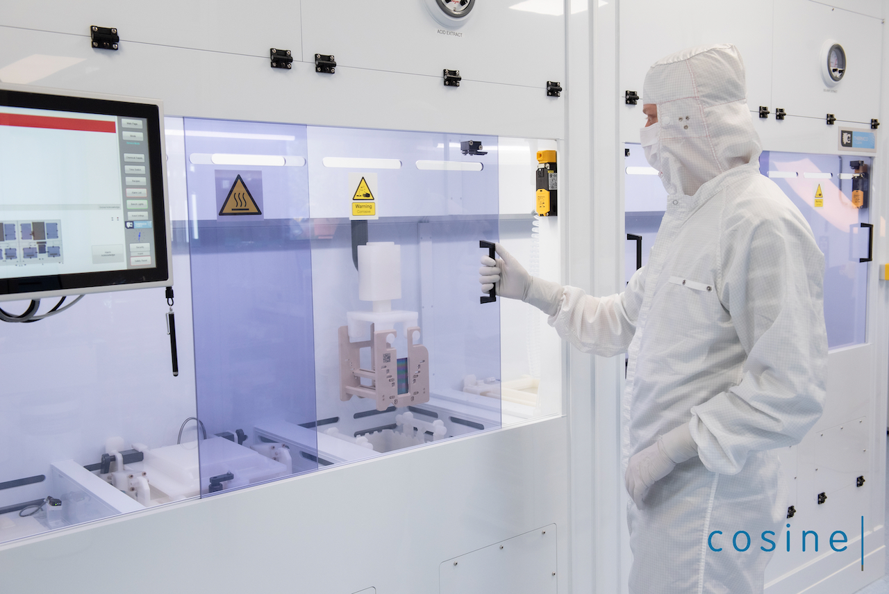
Cleanliness is paramount to the SPO technology. The mirror plates are cleaned in industrial wet benches with a SC-1 cleaning 10003367909 and then dried. This results in hydrophilic (‘activated’) surfaces, free of particulate contamination or drying stains. The hydrophilic surfaces are key to direct silicon bonding, as explained in the next section. The photographs in Figure 8 show the fully automated cleaning wet bench at cosine, which is used to prepare the SPO mirror plates for stacking.
4.4 Stacking of mirror plates
SPO stacks hold together and maintain their shape without adhesive between the mirror plates. This direct bonding process can take place at room temperature and is widely used to join glass or silicon surfaces to each other Shimbo1986 ; Maszara1988 . The two mating surfaces need to be chemically prepared (i.e. activated) and need to be clean, smooth, and conforming for a direct bond to take place. After activation, a thin layer of OH- groups is present on both the ribbed and the reflective sides of each mirror, forming silanol (Si-OH) groups gosele . These absorbed water molecules form a bridge (Si-OH+HO-Si) across the two bonding surfaces that is maintained via Van-der-Waals forces for temperatures ranging from 10∘C to 110∘C gosele . Furthermore, post-stacking thermal treatment, such as annealing above 110∘C, enables the silanol bonds to transform into stronger siloxane (Si-O-Si) bonds gosele . During annealing, the interface dries steadily and siloxane bridges form across the bonding surfaces. For temperatures below 1000∘C, the bonding energy is limited by the area in contact, which is itself limited by surface roughness gosele . Annealing at temperatures above 1000∘C can increase the contact area through viscous flow of the oxide, which then fills up the micro-gaps at the interface to form additional siloxane bonds gosele . SPO mirror surfaces have a micro-roughness lower than 0.5 nm RMS and the flatness over length-scales of several tens of millimetres is better than 100 nm, which means that annealing stacks at temperatures between 150∘C and 1000∘C is sufficient. This is confirmed by environmental testing (see Section 4.6). Note that the excess water can also exude over time and siloxane linkage can form after months of storage gosele .
The plates are stacked in a concave mandrel, starting with a plate placed with the reflective side in contact with the mandrel and ribs pointing inwards, called the base plate. The mandrel is polished with the design shape of the stack. It can be cylindrical or conical, and can feature additional meridional curvature. The next plate is then brought into a similar shape as the base plate by using a ’die’, a tool with the same figure as the mandrel. The plate is attached with the mirror surface to the die, resulting in the ribs pointing outwards. The two plates are brought into close contact such that the two sets of ribs make contact and that direct bonding starts. In that moment, the plate copies the shape of the mandrel. This is the first reflective plate of the stack. The die then releases the plate and the process can be repeated, with the only difference being that the next plates are bonded with their ribs to the mirror surface of the upper plate in the stack. At the end of the process the stack is released from the mandrel and keeps the desired shape through the acting bond forces and the stiffening effect of the ribs.
To achieve good angular resolution, it is important to replicate the initial figure of the mandrels with minimum systematic and stochastic errors. Cleanliness of the plates, mandrel, and die is of prime importance to avoid degrading the figure with bumps created by trapped particles plate after plate. Systematic slope errors can be minimized with optimized plate design and stacking approach.
Note that when it is curved, the mandrel defines only the outer starting radius of a stack. With each plate added, the stacks’ sagittal radius of curvature becomes smaller by the thickness of the mirror plate. In the case of double-reflection optical design such as Wolter I, it is important to align the ribs to several microns. This minimizes loss of open area as the two stacks are aligned one behind the other.
4.4.1 Stacking robots
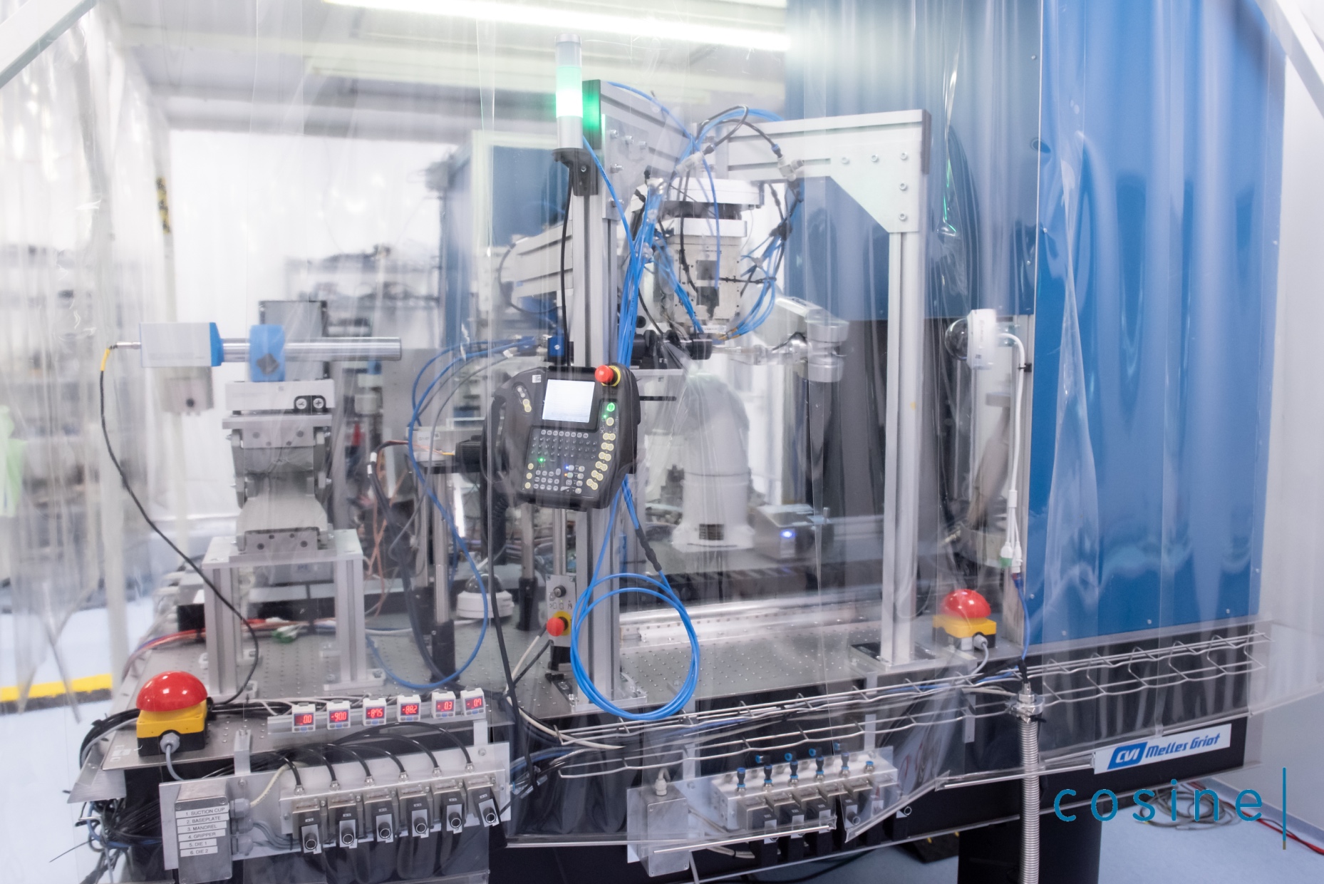
Automated stacking robots have been developed to meet the mass production and quality requirements of SPO technology: automation provides cost-efficiency, improves repeatability for large series, and ensures the highest standard of cleanliness. The robots are composed of a robotic arm equipped with a plate gripper, a die attached upside down, and a mandrel which rests onto an hexapod (Figure 9). The hexapod is on a linear translation stage that allows moving the mandrel and the stack from the die to an optical metrology system.
The stacking process starts with a batch of several tens of plates loaded in a container that are cleaned and activated (Figure 8). The container is loaded into the robot, which is placed inside an ISO-class 5 clean area to keep the plates from accruing particulate contamination. The robot extracts the first plate from the container, aligns it to the gripper, and places it on the mandrel, as described in Section 4.4. A second plate is extracted, aligned to the gripper and attached to the die with the ribs pointing downwards. The mandrel and die are brought into close contact until the ribs align and the bond is created. Then the die releases the plate. The first reflective plate is now bonded to the base-plate. The stack is translated to the in-situ metrology, which measures the figure of the bonded plate, determining not only the shape, but also the cleanliness and therefore the quality of the bond. The robot then proceeds to extracting the next plate, attaches it to the die and the stacking process repeats, this time with the ribs bonding to the mirror surface of the stack on the mandrel.
The process repeats until the desired stack height is reached. Stacks up to 70 plates have been manufactured, 35 plates being the most common so far. Once the stack is finished, it is released from the mandrel and a final inspection is performed to measure the outer geometry and to visually check for defects.
Prior to stacking, the mandrel axis is aligned with the die axis. The plate gripper, which is the reference for the plates alignment, is also aligned with respect to the die and mandrel. A robot is configured for one specific set of stacks defined by its mandrels and plate types. The robot needs to be reconfigured to produce stacks of different radii, plate geometry or figure.
The stacking process takes about 5 minutes per plate and can run completely autonomously. This is the result of more than 15 years of development Gunther:2006uy . The degree of automation, the reliability and speed of the stacking robots is expected to further increase as production of the flight models for Athena are being setup.
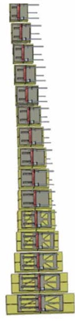
4.5 Mirror modules
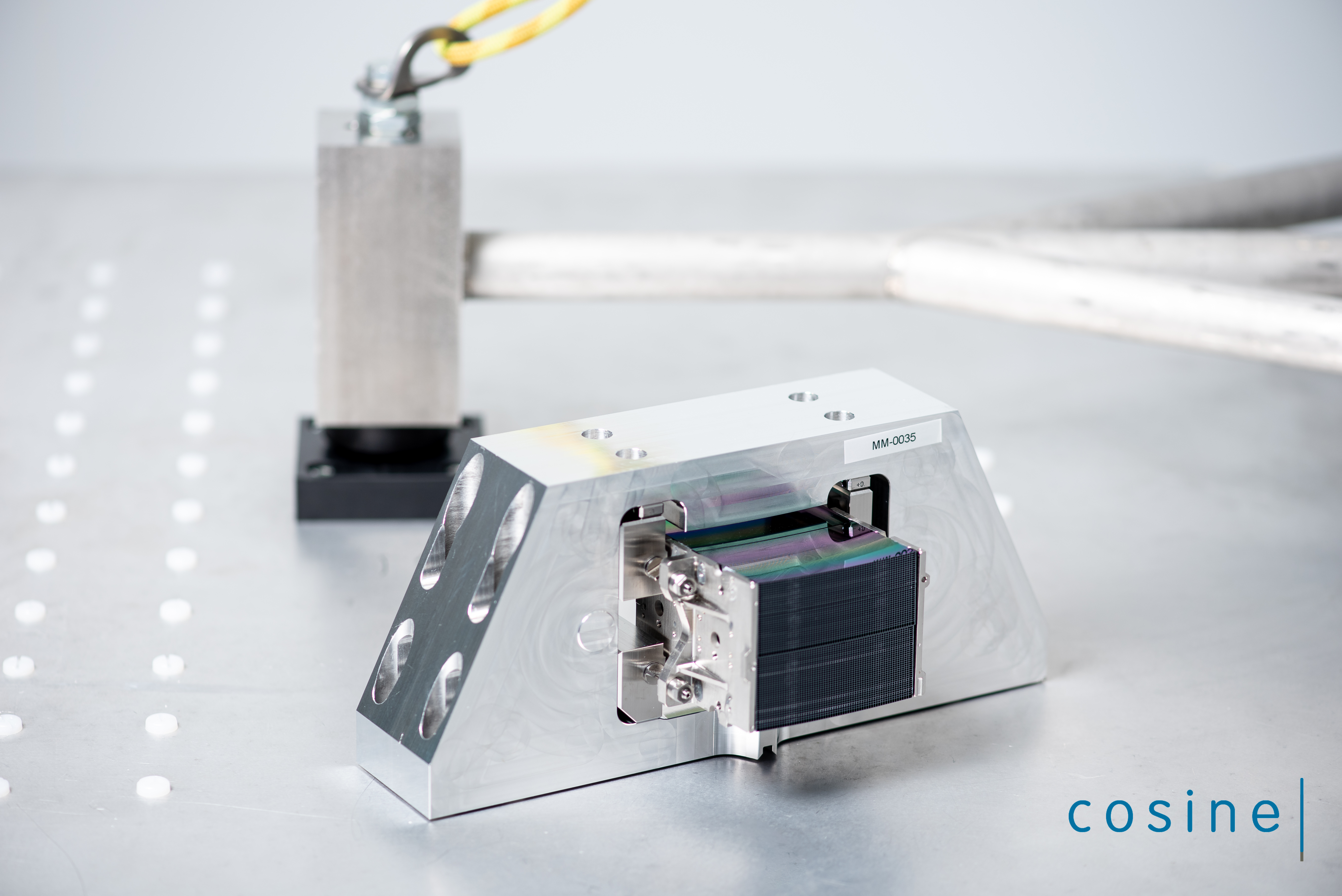
SPO consists of stacks of mirror plates with a shape that is driven by the mandrel. In the case of a Wolter I optical design, two different stack shapes (and consequently, two mandrels) are needed: primary and secondary stacks for the two reflections. When aligned after each other, these stacks form a so-called X-ray Optic Unit (XOU). The fact that the primary and secondary stacks are initially disjoined represents a challenge as their relative alignment can influence greatly the optical quality of the XOU. Their optical axis must be co-aligned along with the mirror plates ribs and membranes. Then this alignment must be frozen. This is done by gluing two side plates to the stacks, commonly referred to as brackets, which then form a mirror module (MM). A MM is thus a stand alone X-ray focusing optics assembly with mechanical interfaces. In the current design, Athena MMs are made of two XOUs co-aligned to be confocal, glued in between a pair of brackets (Figure 10).
The brackets are made of an austenitic nickel-iron alloy containing 36% nickel (Invar 36), a material with very low coefficient of thermal expansion of K-1, close to that of silicon K-1. Their role is to freeze the alignment of the stacks, protect the stacks, provide interfaces between the MM and any support structure or mount, and provide a mechanical reference for the optical axis of the MM. The brackets can also provide interfaces to baffles or aperture mask. Low-outgassing and low-shrinkage epoxy is used to affix the brackets to the sides of the stacks. The interface points of the brackets are called ears (visible on the left hand side of Figure 10).
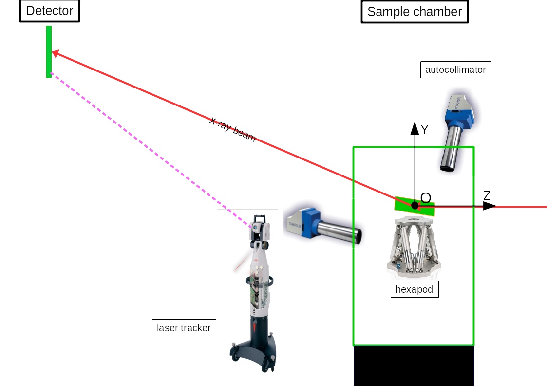
The alignment strategy is as follows Barriere:2019tf ; Barriere:2021vp : the brackets are aligned with respect to each other using a tool providing six degrees of freedom to each bracket. The primary stack is then glued to the brackets. This alignment relies on mechanical metrology with a coordinate measurement machine (CMM). This assembly is then brought to a synchrotron facility where a monochromatic, low-divergence, X-ray pencil beam is available. Currently this is done at the X-ray Parallel Beam Facility 2 (XPBF 2) synchrotron beamline, which is installed in the laboratory of the Physikalisch-Technische Bundesanstalt (PTB) at the synchrotron radiation facility BESSY II in Berlin handick:2020SPIE . An additional beamline is planned to become operational in 2022 at the ALBA synchrotron facility in Barcelona Heinis:2021ud . The XPBF 2, tailored for the development of Athena’s MMs, provides a 1-keV beam monochromatized and collimated by a toroidal mirror with multi-layer coating, allowing beam dimensions between 0.050.05 mm2 and 77 mm2. The detector is placed at 12 m0.5 m from the sample, and its position is monitored by a laser tracker.
At the XPBF 2, the direction of the incident beam is used to define the optical axis for the future MM. The primary stack, already glued within the brackets, is aligned to bring its optical axis parallel to the beam. Then the secondary stack is brought in and the rest of the alignment is done in double reflection. The secondary stack is aligned with respect to the first stack to minimize the intersection of the ribs and membrane (i.e. maximize throughput of the XOU), bring the point spread function (PSF) at the nominal position, and obtain the best possible optical quality (co-align the stacks’ optical axes).
Pencil beam raster scans are used to determine the three-axis orientation of the primary stack with respect to the beam, as well as of the secondary stack with respect to the primary stack Barriere:2019tf . The position of the incident beam onto the primary stack as well as the position of the beamspot recorded on the camera are reconstructed in a common coordinates system. An analytical three-dimensional model of the optic is used in a ray-trace function that transforms incident position into position on the camera. This function is used to fit the orientation of a stack in single reflection or double reflection. This method allows precise and deterministic alignment.
4.6 Ruggedisation
As SPO development progresses, it is necessary to validate the technology under launch and orbit environmental conditions 10.1117/12.2594230 . Payloads undergo high levels of vibrations and shocks during a rocket launch and fairing separation. It is therefore crucial to check that the MMs are robust enough to withstand such conditions and ensure that their mechanical stability and optical performance will remain stable before, during, and after launch. Environmental testing also allows identifying potential design issues and correcting them. A ruggedisation process is a key element of the SPO development.
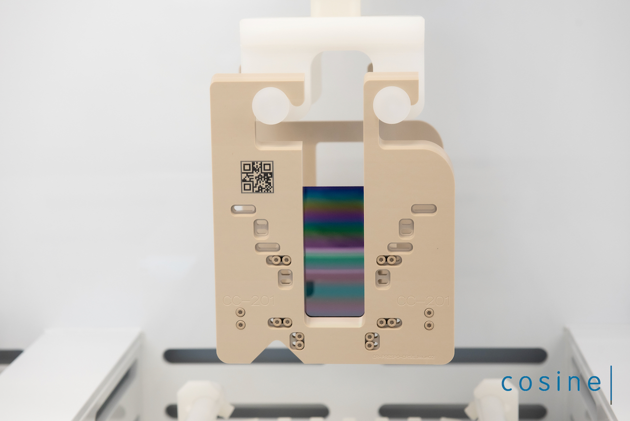
Thanks to its modular nature, SPO can be tested at MM level. MMs are submitted to vibration and shock tests, in accordance with Athena’s launch vehicle and mission requirements. The MMs are characterized with X-rays before and after each test to verify that the performance remains unchanged (Section 4.7). MMs are first integrated into a device under test (DUT, see Figure 11) that is representative of a mirror structure and enables interfacing the MM with test equipment (shock table, shaker, vacuum chamber).
Vibration testing consists of two steps performed successively: sine qualification and random qualification tests. Two triaxial acceleration sensors (pilots) are mounted to the test mount to control the shaker input to the MM. The dynamic response of the MM is monitored on both brackets, close to the MM center of mass. Two single axis accelerometers are also used to monitor the dynamic transfer over the mechanical shims. These mechanical shims are used to preload the dowel pin (DP) flexures used to mount the MM and to statically mimic the expected dynamic structural distortions of the mirror structure during low frequency (sine) and vibro-acoustic (random) mission phases. The Athena sine qualification test levels are shown in Table 1.
For the random test, Athena qualification and notched levels that have been used are presented in Table 2. All random runs at qualification level are preceded by a low level ramp up, meaning a sequence of runs at -12 dB, -9 dB, -6 dB, and -3 dB for 30 seconds each. These runs are used to predict the 0 dB response levels at the MM center of mass and to check that the design limit load (DLL) values are not exceeded.
Frequency signature test runs (also called resonance searches) are performed before and after each high-level qualification test run to detect any potential changes in structural behavior of the MM or test setup. A test run is considered successful if the change in frequency is less than 5%.
| Excitation direction | Frequency | Amplitude | Sweep rate |
|---|---|---|---|
| In-Plane (X, Y) | 5 Hz | 11 mm | 2 Oct/min |
| 17 Hz | 13 g | ||
| 100 Hz | 13 g | ||
| Out-of-plane (Z) | 5 Hz | 11 mm | 2 Oct/min |
| 19 Hz | 16 g | ||
| 100 Hz | 16 g |
| Direction | Frequency | Power Spectral Density (PSD) | Overall input |
|---|---|---|---|
| X | 20-100 Hz | +10 dB/Oct | |
| 100 Hz | 0.05 g2/Hz | ||
| 100-200 Hz | 0.20 g2/Hz | 9.3 g-rms | |
| 200-400 Hz | 0.05 g2/Hz | ||
| 400-2000 Hz | -15 dB/Oct | ||
| Y | 20-100 Hz | +10 dB/Oct | |
| 100 Hz | 0.05 g2/Hz | ||
| 100-200 Hz | 0.20 g2/Hz | 9.3 g-rms | |
| 200-400 Hz | 0.05 g2/Hz | ||
| 400-2000 Hz | -15 dB/Oct | ||
| Z | 20-100 Hz | +10 dB/Oct | |
| 100 Hz | 0.05 g2/Hz | ||
| 100-200 Hz | 0.70 g2/Hz | 6.0 g-rms | |
| 200-400 Hz | 0.05 g2/Hz | ||
| 400-2000 Hz | -15 dB/Oct |
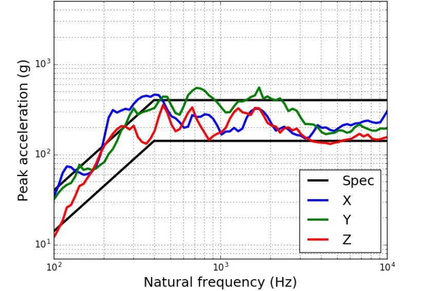
Shock testing is performed with a shock table and shock levels are defined by a shock response spectrum (SRS). Before the test, a calibration of the ringing plate is performed using a dummy middle radius MM.
Mechanical shims are used to preload the DP flexures similarly to the vibration test. There, the preloading and SRS level simulate mirror structure distortions during one of the most dramatic event of the launch sequence as seen by the payload corresponding to the the release of the launch locks that will hold the mirror assembly during launch and are release once in space (shown in Figure 22). Figure 12 displays a SRS as measured on the test mount (also called input SRS) of a MM. Note that the SRS is isotropic, enabling the testing of all three axis in a single shock. Two high-speed cameras, each looking at one side along the optical axis, are used to assist in identifying failures, as well as their modes. Resonance searches are also performed to check on the structural integrity of the MM.
SPO stacks have been tested as standalone items, then again once assembled into MM for the different radii used for development (representative of the inner, middle and outer radii of Athena). At the time of writing, the actual Athena flight configuration is also starting to be tested with the first row-08 MM having passed both vibrations and shock tests at qualification levels (Figure 10). Such testing campaigns at qualification levels will continue and extend to all rows of Athena, further ruggedizing SPO technology in general. For the flight model of Athena, each MM will undergo a workmanship test consisting of random vibration tests at acceptance level; additional environmental tests will be conducted at the mirror assembly level once the MMs are integrated into the mirror structure.
4.7 X-ray characterization
Optical metrology of the SPO stacks taken during manufacturing produces a wealth of information on the eventual X-ray performance of the optics. However, regular X-ray characterization remains an important part of the development process, as it is done at the same energy and incidence angle used during the actual use of the optics during flight.
4.7.1 SPO stack characterization
Given the number of SPO stacks that are made, and the fact that individual stacks are not imaging systems, it has long been recognized that a dedicated facility with a high flux of X-rays is required to meaningfully support the development of the optics Collon:2006wz ; krumrey_x-ray_2010 ; ackermann_performance_2009 ; krumrey_2016 . Characterization by means of a low-divergence () pencil beam of X-rays, as opposed to the more customary full-flood illumination, makes it possible to probe the surface of each plate in a stack with high spatial resolution, and arrive at the characterization of the surface slope errors and of the millimeter-scale defects contributing to the widening of the beam Vacanti:2019wr . At the time of writing, two dedicated beamlines are available in the PTB laboratory at the BESSY II synchrotron krumrey_x-ray_2010 ; krumrey_2016 , and an additional beamline is being assembled at ALBA Heinis:2021ud (Section 4.5).
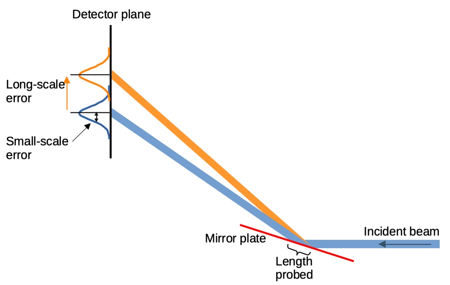
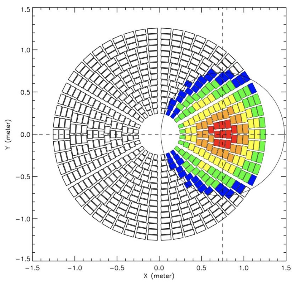
For their characterization, the samples are moved in a rectangular pattern of columns and rows through a X-ray beam. In Figure 13 we show how the samples are placed in the beam and measured. Scan columns are spaced usually by , and scan rows are spaced by . This so-called standard scan pattern probes only a fraction (about ) of the total reflecting area in an SPO stack. Tests have shown that the results obtained in this manner are representative of the complete surface. That is, making the scan columns more densely spaced, or using overlapping beams, does not add any new information on the properties of the stack derived from the data.
The data collected during a standard scan are processed to identify and isolate the reflected X-ray beam, then characterized by its centroid and RMS length and width. After this morphological characterization, the positions of the images and the sample in the laboratory frame are determined and converted to a common coordinate frame for further analysis. Each reflected beam probes between and along each of the pores, depending on the type of stack and the angle of incidence used in the measurement. Maps of the variation of the RMS length of the images already reveal good and bad areas on each plate.
A global quality indicator of the properties of the reflecting surface is derived by superimposing all the reflected images on their barycenters and calculating the half energy width (HEW) of the resulting image. This indicator is called the on centroid performance of the sample and is usually expressed in units of the HEW of the direct beam, and it represents the average surface quality on length scales of the order of a few to several millimeters.
More complex metrics can be obtained by processing the data further. A model of the stack is introduced, and the expected position of the barycenters of the reflected X-ray beam is calculated. By comparing the expected and the measured positions, a displacement vector is obtained for each reflected image. All the images are then superimposed on the common barycenter, where they would all end up if the SPO stack behaved ideally, and shifted by the displacement vector calculated. The HEW of the resulting image (Figure 15) is a metric of the optical quality of the stack, and it represents the contribution of the stack to the optical quality of a pair of stacks arranged to form an imaging system. This indicator is called the on-model centroid performance of the sample.
Data from the raster measurement can be used to derive a variety of performance indicators related to the optical quality of the stack. We mention here three of them, illustrated in Figure 14, they are:
-
•
The broadening of the reflected beam, a marker of short length-scale errors;
-
•
The (best-fit) meridional curvature, a marker of global figure errors;
-
•
The difference between the measured and expected position of the reflected beam taking into account the best-fit meridional curvature, a marker of long length-scale figure errors.
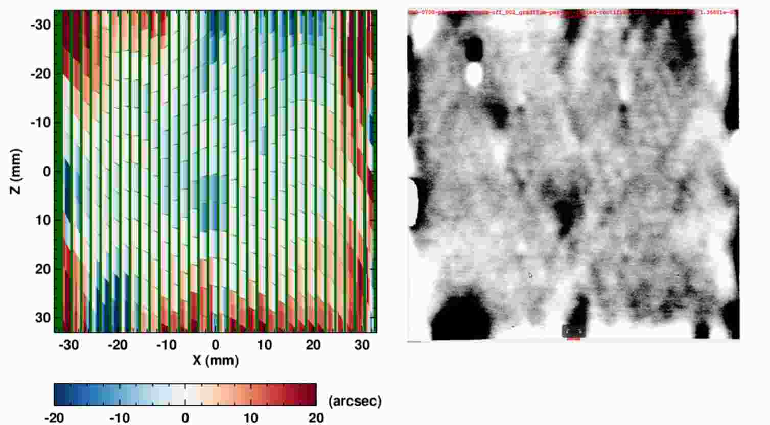
The same analysis that leads to the calculation of the displacement vectors is also able to estimate the local surface normal seen by the X-ray beam, and the difference between ideal and actual surface normal. This information is coded in a synoptic slope error map, an example of which is shown in Figure 16. The map codes information for the entire stack: each block is made of a number of smaller rectangles, one for each plate, color coding the local slope error experienced by the X-ray beam (left to right for increasing plate number). These maps can be compared to similar per-plate maps obtained during manufacturing of the stack. It can be seen in the Figure that the same features are visible in both maps. This proves that cleanroom metrology provides information that is immediately relevant for the X-ray behavior of the optics. The map also shows that the error experienced by the X-ray beam at each location is nearly the same irrespective of plate number. The shape of the first plate in the stack is almost exactly reproduced across the entire stack.
4.7.2 XOU and MM characterization
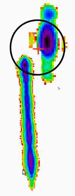
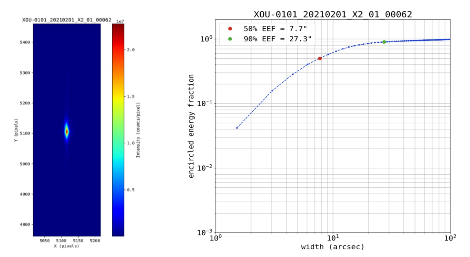
Once assembled into an imaging system (XOU), a primary-secondary stack doublet can be characterized with the same standard scan used for the characterization of single stacks. The analysis of the data proceeds along the same lines described in the previous section, but now the individual images can be combined to arrive at an estimate of the HEW of the imaging system (Figure 17). Owing to the use of a pencil beam, it is now possible to analyze the performance of the optics along different axes, for instance by looking at how the HEW changes with plate number. Other spatial selections are possible, leading to the ability to compare the performance of different regions of the optics, that can be related to the indicators derived from the cleanroom metrology.
5 Athena
5.1 Introduction
The Athena mission – Advanced Telescope for High-ENergy Astrophysics - is an X-ray observatory designed to address the Cosmic Vision science theme ’The Hot and Energetic Universe’. The mission was selected as the second L-class mission in ESA’s Cosmic Vision 2015–25 plan. The mission is in its final preparation stage (Phase B1) at the time of writing and is expect to proceed into implementation soon. Athena will be an X-ray observatory with a wide energy range (0.2 -15 keV) and will include two innovative instruments to accomplish its science goals Nandra:2013ue .
The first instrument, the X-ray Integral Field Unit (X-IFU) X-IFU_pajot , provides spatially-resolved high-energy resolution spectroscopy, 2.5 eV, over a field of view of 5 arcmin, specifically aiming at spectroscopy of faint extended sources. This is an extremely advanced instrument requiring a complex cryogenic chain to allow the operation of a focal plane array based on transition edge sensors cooled down to 50 mK.
The second instrument, the Wide Field Imager WFI_Norbert , is a silicon-based detector using DEPFET active pixel sensor technology with around 150 eV energy resolution over a very large field of view of 40 arcmin, aiming at deep surveys.
To provide signal to these instruments, Athena requires the largest X-ray telescope ever built, targeting an effective around 1.4 m2 at 1 keV and 5 arcsec HEW angular resolution (driven by the faint confusion limited survey mode for the WFI instrument). As illustrated in Figure 18, the Athena optics is coupled to the science instruments via the spacecraft metering structure. Supported by an hexapod system, the optics can be tilted to select the desired instrument, the X-IFU or the WFI. The Athena Mirror Assembly (MA) consists of 600 SPO MMs mounted in metallic structure (details in Section 5.3).
Creating the optics technology for Athena is a formidable task, being addressed in a holistic and structured approach. From the very beginning the performance requirements were considered together with the programmatic constraints, in particular time and cost to build the flight optics, and the compliance with the environmental conditions of launch and space operations. Modularisation and serial production are essential for the production of the Athena optics, given its size, and MMs are rugged by design. Even the first optics demonstrator had to be compatible with mass production requirements of hundreds of mirror modules and hundred thousand mirror plates.
The development of the Athena optics is funded and led by ESA, in very close collaboration with industrial and institutional partners. With increasing maturity a well-coordinated consortium was formed, led by cosine Measurement Systems, which ensures a gradual, evolutionary transition from the study and development to the implementation phase of the Athena mission.
The size of the Athena optics also requires the creation of novel dedicated facilities to:
We discuss hereafter the design and performances of the Athena optics as known at the time of writing, knowing that evolution is still likely to take place. The coordinate system in use is as follows: the Z axis is along the optical axis, with its direction along the propagation of the X-rays. The Y axis is radial, pointing outwards. X completes the orthogonal coordinates system.
5.2 Optical design
With SPO, a given optical design is realized by incrementally copying and modifying the figure provided by a pair of mandrels, one for the primary and one for the secondary. The mandrel defines the figure of a putative ”zero plate” in the stack: each new plate copies the figure of the previous plate, and at the same time it introduces small changes in the figure, so as to keep the aberrations to a minimum. The optical design of the Athena is based on the Wolter-Schwarzschild Chase:73 design of X-ray optics. The Wolter-Schwarzschild condition is only met exactly by one primary-secondary plate pair, called the reference plate pair. Once the relative orientation of this pair is set, the orientation of the remaining plates is given by their physical properties, and this leads to small departures from the ideal configuration.
As described above (Section 4.4), a stack is built from larger to smaller radii. The shape of the plate at the larger radius is given by a mandrel that is designed to realize the ideal optical design at that radius. From there on, as the stack grows, and under the assumption that within a stack the plates have all the same geometry, each new plate takes a smaller sagittal radius until the desired number of plates has been stacked.
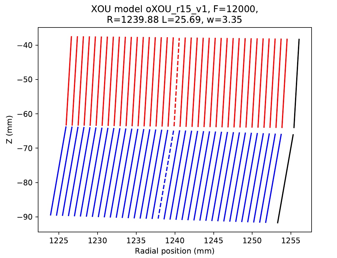
We have therefore the situation described in Figure 19, where each reflecting surface has a different sagittal radius. The figure shows a cut through the central meridional plane of a primary and secondary stack. For the reference plate pair (dashed) the Wolter-Schwarzschild (W-S) condition holds:
| (2) |
and
| (3) |
where and are the angle that the primary and secondary plates form with the optical axis.
The W-S condition shows that plates must be placed at different angles with respect to the optical axis, depending on the (sagittal) radius they are at. For the primary stack the angle variation is then
| (4) |
and similarly for the secondary stack. This angle change is implemented in the plates, and is called the wedge of the plates (Section 4.1). If we take mm, mm and mm we arrive at values of the wedge of the order of 3.3 arcsec for the primary plates, and 3 times as large for the secondary plates. Other wedge combinations are possible ackerman_patent and they are discussed in more detail elsewhere vacanti_2022 .
Improved optical performance can be obtained if instead of the conical approximation a meridional curvature is introduced in the profile of the reflecting surfaces. This must be done by manufacturing suitable mandrels. Just as for conventional replicated shell optics, one can decide to introduce parabolic and hyperbolic profiles vanspeybroeck_design_1972 , or two spherical profiles saha_equal-curvature_2003 , or one conical profile and one spherical one willingale_improving_2010 . Which one to use depends on the parameters of the system and the tolerances that can be achieved in the manufacturing of the mandrels. For Athena the choice has been made to place all the meridional curvature in the secondary stacks, and across the aperture this leads to a meridional radius of curvature of 1 to 4 .
Even with the introduction of a meridional curvature, there are practical manufacturing considerations that contribute to the degradation of the angular resolution. These are discussed in detail elsewhere vacanti_2022 . Here we mention that when building a large segmented X-ray mirror with hundreds of stacks and more than individual plates, it becomes necessary to reduce complexity by manufacturing standard plates; in particular, stacks of the same central sagittal radius will be manufactured to have plates of the same length and with the same wedge, although an ideal design would call for gradual changes in both parameters. These small approximations imply that the best on-axis optical performance that can be achieved by a perfect optical design is of the order of 0.1–0.2 arcsec.
5.3 Design and expected performance for the Athena optics
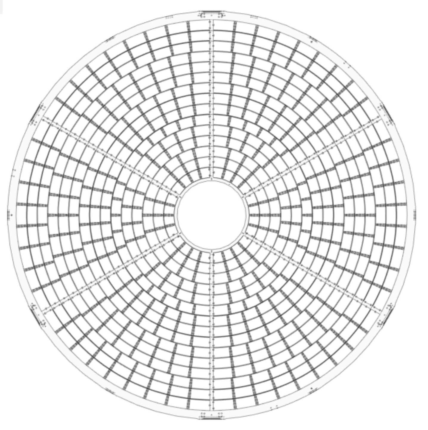
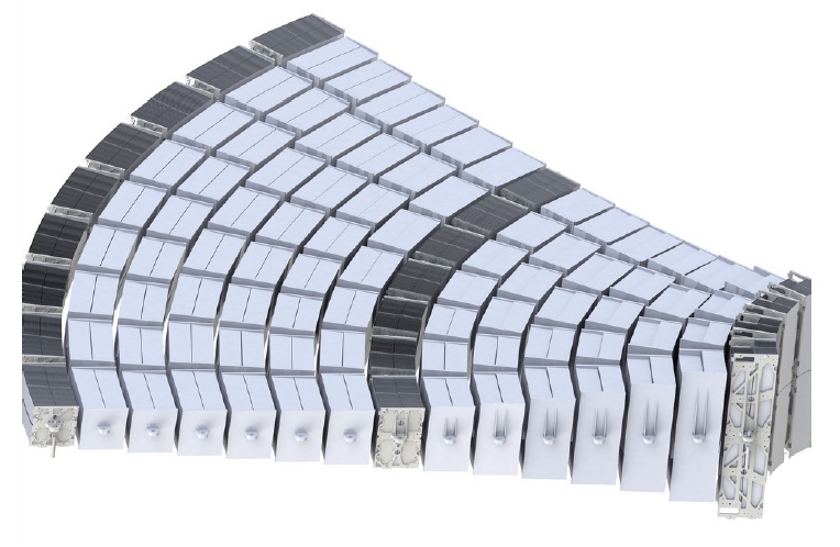
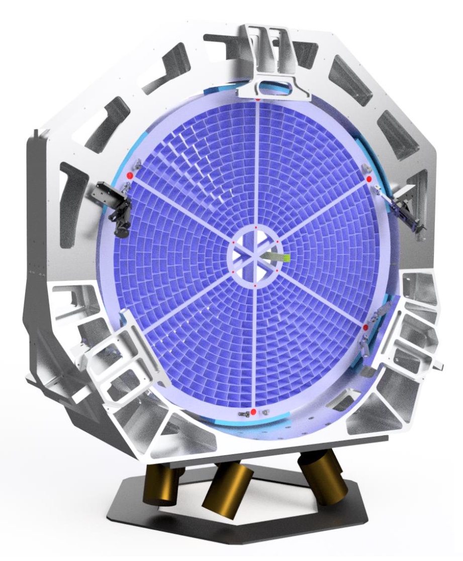
The 600 MMs of the Athena MA are organized in 15 radial rows. The assembly is modular to the row level, where the MM design for a particular row follows the design rules described in Section 5.2. The MMs are placed onto a supporting monolithic Mirror Structure (MS) that has many pockets designed to accommodate the different geometries of the MMs. There is a six-fold symmetry (six petals): structural reinforcement is introduced with six radial spokes running between an inner and an outer rim as shown in Figure 20. The MMs are mounted using sets of DPs which are isostatic mounts that prevent the distortions on the MS to percolate onto the MMs. These DPs are glued to both the MS and the MM brackets.
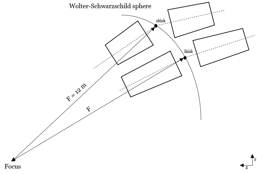
The kinks of the reference plates of each XOU (one MM currently includes two XOUs but can be just a single XOU, see Section 5.2) are placed on a spherical surface with a radius of 12 m (focal length) centred in the design telescope focus (see Figure 21), forming an almost perfect Wolter-Schwarzschild configuration Chase:73 which significantly reduces coma aberrations and therefore provides better angular resolution averaged over the field of view than Wolter I configuration.
|
The width and radial position of each MM design is chosen to maximize the effective area, guaranteeing the necessary clearance to accommodate the mirror structure, the necessary thermal equipment, the range needed for the MM alignment, and the dynamic and thermal distortions expected during launch and operations 10.1117/12.2594443 . An iterative geometric model ensured all the constraints were met which resulted in a layout as described in Table 3.
The MS is thermally controlled with the help of hundreds of heaters and several tens of thermistors. This thermal control system is needed in order to minimize the thermoelastic distortions (and the corresponding optical performance degradation), and to allow the MMs to be kept close to the temperature set-point at which they were assembled and verified on ground (C). At the center of the MS, as close as possible to the mirror node, there are a number of star trackers and other metrology elements needed to achieve the required knowledge of the telescope line of sight (absolute knowledge of 10 arcsec, and relative knowledge of 1 arcsec over 100 ksec).
The MA consisting of the MS, SPO MMs, thermal control system, and other elements is held during launch with the help of six launch lock bipods able to hold up to 60-100 kN each (Figure 20). Once in orbit, these launch locks, which are Hold Down and Release Mechanisms (HDRMs), are released. The MA can then be steered with the help of a set of very accurate actuators in a hexapod configuration, referred to as the Instrument Switching Mechanism (ISM) (Figure 22).
| Row |
|
|
|
|
|
|
|
|
||||||||||||||||||||||||
|---|---|---|---|---|---|---|---|---|---|---|---|---|---|---|---|---|---|---|---|---|---|---|---|---|---|---|---|---|---|---|---|---|
| 1 | 24 | 259.5 | 122.84 | 0.31 | 289.61 | 110.08 | 0.346 | 40.22 | ||||||||||||||||||||||||
| 2 | 24 | 327.7 | 97.29 | 0.392 | 357.81 | 89.11 | 0.428 | 58.08 | ||||||||||||||||||||||||
| 3 | 24 | 395.9 | 80.84 | 0.473 | 426.01 | 74.85 | 0.509 | 75.94 | ||||||||||||||||||||||||
| 4 | 30 | 464.1 | 68.71 | 0.555 | 494.21 | 64.52 | 0.59 | 71.14 | ||||||||||||||||||||||||
| 5 | 30 | 532.31 | 59.91 | 0.636 | 562.42 | 56.7 | 0.672 | 85.42 | ||||||||||||||||||||||||
| 6 | 36 | 600.51 | 53.1 | 0.718 | 630.62 | 50.56 | 0.753 | 79.84 | ||||||||||||||||||||||||
| 7 | 42 | 668.72 | 47.68 | 0.799 | 698.82 | 45.63 | 0.835 | 75.85 | ||||||||||||||||||||||||
| 8 | 42 | 736.92 | 43.26 | 0.881 | 767.03 | 41.57 | 0.917 | 86.06 | ||||||||||||||||||||||||
| 9 | 42 | 805.12 | 39.6 | 0.962 | 835.23 | 38.17 | 0.998 | 96.26 | ||||||||||||||||||||||||
| 10 | 48 | 872.57 | 36.43 | 1.043 | 902.67 | 35.31 | 1.079 | 90.62 | ||||||||||||||||||||||||
| 11 | 48 | 940.02 | 33.91 | 1.124 | 970.12 | 32.85 | 1.16 | 99.45 | ||||||||||||||||||||||||
| 12 | 48 | 1007.47 | 31.63 | 1.204 | 1037.56 | 30.71 | 1.24 | 108.28 | ||||||||||||||||||||||||
| 13 | 54 | 1074.91 | 29.64 | 1.285 | 1105.01 | 28.83 | 1.321 | 101.93 | ||||||||||||||||||||||||
| 14 | 54 | 1142.35 | 27.89 | 1.366 | 1172.44 | 27.17 | 1.402 | 109.77 | ||||||||||||||||||||||||
| 15 | 54 | 1209.79 | 26.33 | 1.447 | 1239.88 | 25.69 | 1.483 | 117.62 |
The ISM enables the focusing of the telescope onto one of the two instruments, and even to different locations within their respective detector arrays in a large range of motion (including movements along the line of sight from +5 to -35 mm). This flexibility is also key to compensate for misalignments introduced during launch or due to thermal effects. The requirement is to be able to position the focal point of the telescope with an accuracy of m onto the detector plane (with a much tighter stability of only m over 100 ks) and m along the line of sight.
 |
 |
|
|
5.3.1 Effective area
The reference telescope design has been simulated using a ray tracing software 10.1117/12.2530682 and is estimated to deliver the effective area performance shown in Table 4. This performance estimation assumes that the mirror plates are coated with a recipe consisting of iridium and an overcoat of silicon carbide (SiC). This coating recipe is still assumed as the baseline at the time of writing due to the demonstrated compatibility of both layers with the SPO process, in particular cleaning and activation 10.1117/12.2562430 . Nevertheless, there is a considerable effort ongoing to verify other overcoats like B4C or carbon, with very promising results. Figure 23 shows the differences in effective area for different coating recipes, showing that a significant improvement can be expected at the low energies for overcoats of either B4C or carbon (see also Section 4.2). Multilayer recipes will also be explored to provide effective area enhancement close to the Fe line, which will be particularly relevant to the X-IFU instrument.
| Row |
|
|
|
|
|
|
||||||||||||
| 1 | 320 | 313 | 311 | 242 | 271 | 263 | ||||||||||||
| 2 | 463 | 450 | 447 | 325 | 364 | 305 | ||||||||||||
| 3 | 599 | 579 | 573 | 390 | 422 | 90 | ||||||||||||
| 4 | 700 | 672 | 665 | 420 | 405 | 6 | ||||||||||||
| 5 | 827 | 790 | 780 | 456 | 279 | 1 | ||||||||||||
| 6 | 916 | 869 | 856 | 461 | 62 | 0 | ||||||||||||
| 7 | 1001 | 944 | 928 | 456 | 11 | 0 | ||||||||||||
| 8 | 1114 | 1045 | 1024 | 456 | 3 | 0 | ||||||||||||
| 9 | 1259 | 1210 | 1348 | 374 | 4 | 0 | ||||||||||||
| 10 | 1335 | 1279 | 1434 | 258 | 1 | 0 | ||||||||||||
| 11 | 1432 | 1367 | 1536 | 158 | 0 | 0 | ||||||||||||
| 12 | 1523 | 1449 | 1636 | 88 | 0 | 0 | ||||||||||||
| 13 | 1584 | 1501 | 1697 | 54 | 0 | 0 | ||||||||||||
| 14 | 1665 | 1571 | 1775 | 48 | 0 | 0 | ||||||||||||
| 15 | 1740 | 1636 | 1844 | 55 | 0 | 0 | ||||||||||||
| Total | 16478 | 15675 | 16854 | 4241 | 1822 | 665 |
The above estimation includes the losses due to the following effects:
-
•
fixed length of plates within a stack,
-
•
-1/+1 wedge optical configuration,
-
•
alignment and figure errors,
-
•
surface roughness of the reflecting surfaces,
-
•
variable axial gap between the primary and secondary stack,
-
•
parallel ribs,
-
•
plate stacking rotation error.
All of these losses (included in the numbers in Table 4) add up to around 10% at 1 keV but go up to 17.5% at 7 keV.
However, there are some additional losses that are not included in the effective area numbers reported here which should be applied on top of the effective area numbers presented. These include:
-
•
coating imperfections,
-
•
particulate contamination (initial and accumulated until launch),
-
•
mirror module rotations around X,Y axes,
-
•
misalignment between MA optical axis and line of sight,
-
•
misalignment between line of sight and target,
-
•
margins (other causes not identified yet).
The amount to be allocated for these additional losses is still uncertain in many cases. It is expected to add up to 10-20% loss depending on the energy, to be subtracted from the numbers in Table 4.
5.3.2 Vignetting
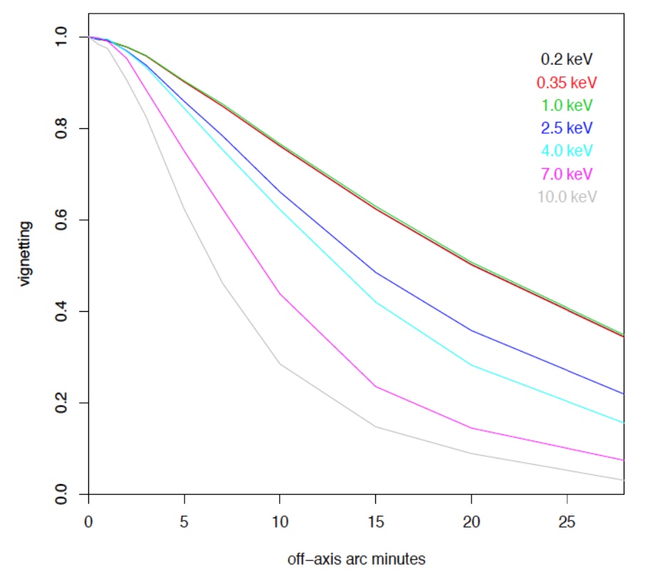
The estimated vignetting factor for the MA was calculated for different energies (Figure 24). The steeper vignetting curve at higher energies reflects the fact that the main contributor for the effective area at these energies are the inner radii MMs. These inner MMs have longer plates and therefore are more susceptible to shadowing by both the membranes and the ribs with off-axis illumination. The need to limit the effective area loss at these high energies is the driver for the alignment of the optical axis with respect to the line of sight, which needs to be accurate to the level of a few arc-seconds.
5.4 Mirror module alignment
In order to achieve the 5 arcsec HEW angular resolution for the Athena MA, a novel method was developed to enable the alignment of the MMs into the MS with an accuracy better than 1.5 arcsec (1 arcsec as a goal). There are a number of other critical requirements to address during MM integration: the cleanliness level needs to be maintained to ISO5/6 level, the process has to allow a rate of 2 MMs/day (in order to be compatible with the schedule allocation for the flight programme), it should be possible to set an arbitrary sequence of the integration and there should be the possibility to remove, re-align or replace any MM along the aperture.
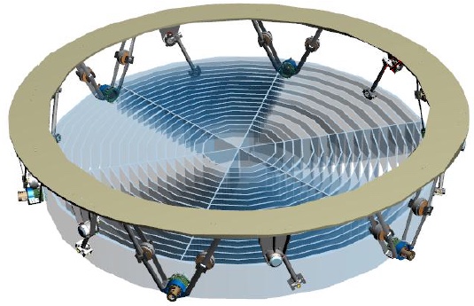
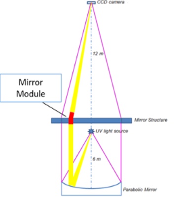
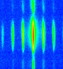
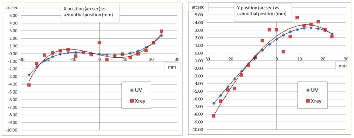
The MM alignment concept was developed at Media Lario (Bosisio Parini, Italy). It consists of a vertical optical bench to capture the focal plane image of each SPO MM while illuminated by a reference plane wave at a wavelength of 218 nm (UV). This is possible because it has been confirmed by simulations and experimentally that the centroid of the PSF is at the same location in UV and X-rays 10.1117/12.2272997 (Figure 25). Working with UV illumination simplifies the alignment operation and allows the use of space-qualified gluing processes in air.
The light emitted by the UV source is reflected by a parabolic mirror to generate a beam collimated to better than 95 km effective source to MM distance, thus approximating illumination from a source at infinity. Each MM focuses the collimated beam onto a CCD camera placed at the focal position and the acquired PSF is processed in real time to calculate the PSF centroid position and intensity parameters (Figure 25). This information is then used to guide the robot-assisted alignment sequence, which makes use of a manipulator providing six degrees of freedom. Four of those result in a change of the position of the PSF (correction of in-plane and focus errors), and the other two result in a change of the intensity (effective area). A robotic arm holds the MM during glue curing and can correct the alignment during curing using real-time feedback from laser trackers.
 |
 |
|
|
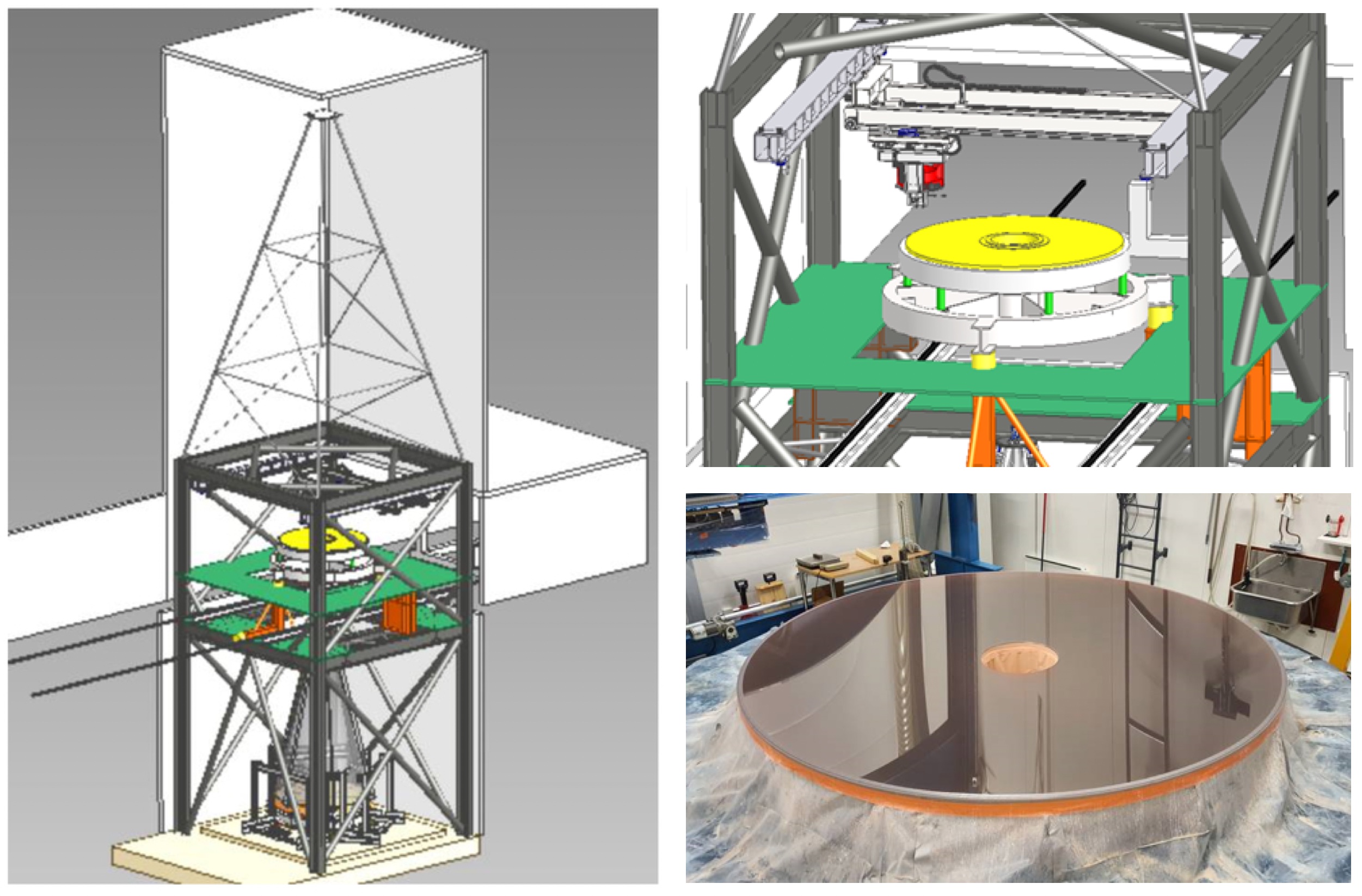
The implementation of this concept is ongoing at the time of writing. The facility requires a building able to accommodate a large UV collimator with 2.5 m diameter (to cover the entire Athena aperture), the MA, and the detector plane necessary for the verification of the PSF centroid position. This is accomplished in a building where the UV collimator is placed around 6.5 m below the ground floor, while the robotic integration and glue injection occur at the level of the ground floor, and the detector is placed 12 m away (total building height of 17 m) to accommodate other necessary equipment (Figure 26).
The UV detector is held in a position 12 m away from the MA, it can be mounted directly on the walls of the clean room of the building or supported by a CFRP structure. Since there is the ability to monitor real time the position of the detector and the MA with the help of an accurate laser tracker system, any relative movements introduced by the building can be monitored and removed in post processing (drifts can also be corrected with the help of a linear actuator stages on which the detector is mounted).
 |
 |
 |
 |
 |
 |
5.5 Mirror assembly X-ray characterization
The need to comply with the tight verification/calibration requirements for the Athena MA is a major challenge, due to its large size. In order to ensure that the uncertainties due to the divergence of the beam are compatible with the accuracy requirements of the calibrations, the source should be positioned at a minimum distance of 300 m. Since the largest X-ray calibration facility in Europe is the MPE Panter facility with a 120 m vacuum tube Panter , this requirement can only be satisfied with either the NASA X-ray & Cryogenic Facility XRCF or a new concept for an X-ray facility, the VERT-X facility 2019SPIE11180E..25P . Both of these approaches are being followed, and the verification and calibration of the Athena MA is expected to be achieved by using both of these facilities.
The NASA XRCF facility has a 518.2 m vacuum tube built for HEAO-B and then rebuilt for the Chandra mirror X-ray characterisation. More recently it has been recommissioned to perform the cryogenic testing of the JWST primary mirrors panels 2009AAS…21342619L . It is now being prepared to perform the first X-ray characterisation with the Athena MA demonstrator (Figure 27). The size of the X-ray beam allows for the testing of one petal of the MA at a time. However, despite the distant location of the X-ray source, there is a significant change in the divergence of the beam within the petal (and even within a MM) that will affect both the effective area and angular resolution characterisation. This will be addressed with post processing enabled by accurate metrology. The MA is mounted vertically in a dedicated structure that limits the effects of sagging due to gravity. This structure interfaces with an hexapod system which enables alignment of the MA in the beam, off-axis characterisation, and defocussing.
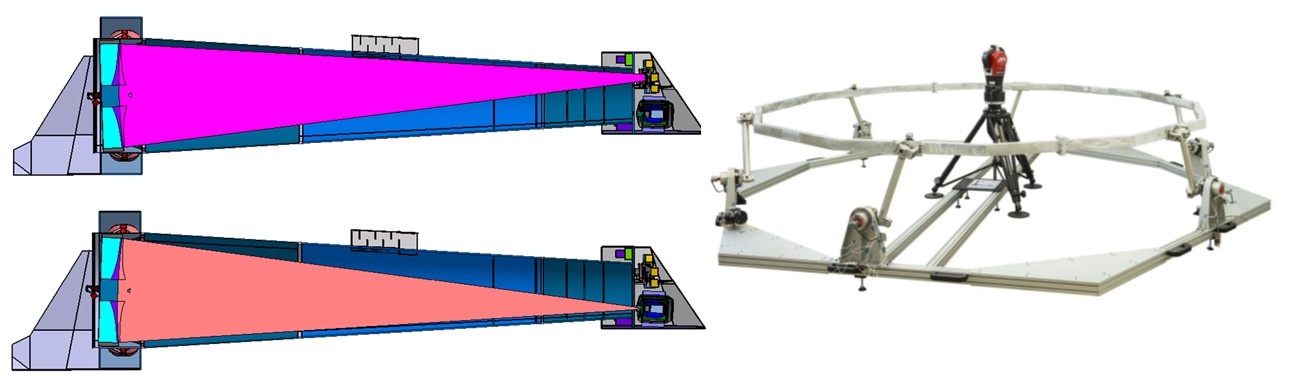
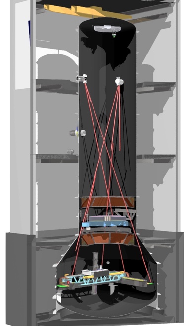
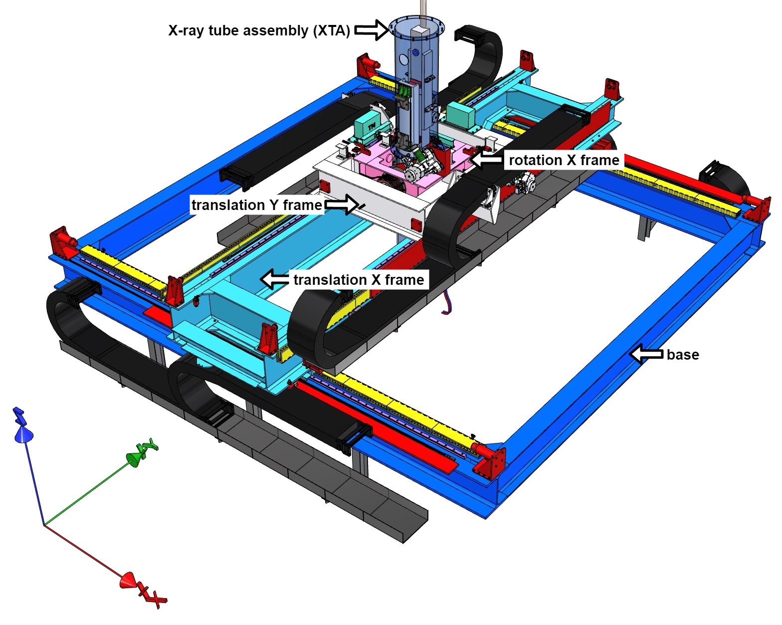
The VERT-X facility relies on a small, highly collimated, vertical X-ray beam that is mounted on a raster scan mechanism, which is able to move along two translations on the horizontal plane and two tilts about the two horizontal axes. In this facility, the source is placed at the bottom, the MA, which is horizontal, is at the ground floor level, and an X-ray detector is placed 12 m from the MA at the top (Figure 28).
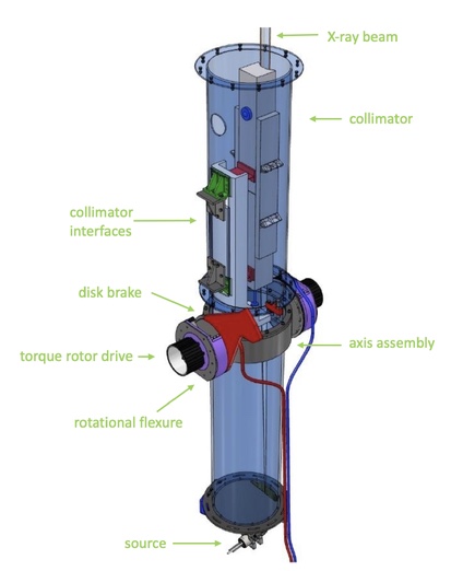
The collimating X-ray mirror of VERT-X is based on a Wolter I configuration of about 1.1 m in length and an average grazing incidence angle of about 0.4 degree. The main driving requirements that led to the definition of the design are related to the needs for high reflectivity in the spectral range between 0.2-12 keV, and the limitation to arcsec for the divergence error of the collimated beam produced by the mirror. The mirror substrate is made of fused silica, and it is held together with a micro-focus X-ray source in a common tube. This assembly generates a collimated X-ray beam of about 61 cm2 cross section.
This X-ray source is moved within the MA aperture with a nominal scan velocity of 30 mm/s. Covering entirely the MA will require a total path length of about 100 m, which is expected to take 1 hr accounting for 15 s of settling time at the start and end of each row. The tube can be tilted not only to cover all the field of view, but also to point up to 3 deg off-axis in order to simulate the stray-light contamination from an off-axis source (Figure 28). Dedicated metrology and a control system is used to correct in real time the misalignments that occur during scanning. The main factors contributing to the wobble of the beam during a measurement are the thermal deformation due to temperature gradient along the raster scan and the non-repeatable runout of the trolley linear guide support system. In both cases the metrology is expected to provide a correction leaving a residual uncertainty of only 0.03 arcsec.
In addition to the collimation advantage (divergence on the order of 1 arcsec, compared to arcmin level at XRCF) VERT-X allows measuring the MA horizontally, which reduces gravity induced sagging errors. The critical items of this facility, the X-ray source and the raster scan mechanism, are being implemented at the time of this writing. The plan is to build the facility next to the MM alignment facility at Media Lario (see Section 5.4). This will significantly ease the logistics associated with the X-ray verification, particularly for intermediate alignment checks in X-ray 10.1117/12.2593670 .
6 Summary and conclusions
SPO uses technology developed over multiple decades by the semiconductor and automotive industries, which have massively invested in the fabrication and processing of silicon wafers. It has become a very mature technology, thanks to the continuous development efforts to prepare the industrial production of the largest X-ray optics yet to be launched into space. SPO is an enabling technology for Athena, and is on-track for meeting the observatory’s ambitous requirements for effective area, angular resolution, and mass. The optics for Athena are under intense development, aiming to start the manufacturing the first flight MMs in 2026. In parallel, facilities for the assembly and testing of the MMs, co-alignment of the MMs in the MA, and ground calibration of the MA are being implemented.
It is already recognized that SPO can be applied to applications other than Wolter I optics for space-borne telescopes. The technique of replication of a mandrel in stand alone stacks of mirror plates can be used for any medium to large series manufacturing of mirrors with pretty much any kind of figure. Whether all the plates are used as mirrors or only the top one is a matter of design. Kirckpatrick-Baez designs or lobster eyes could also be implemented using a similar process. SPO technology also has the potential to create advanced gamma-ray focusing elements via the use of diffraction in the volume of the crystalline plates.
References
- (1) Ackermann, M., Vacanti, G., Vervest, M.: Method for assembling an imaging x-ray optic. NL1041110A;NL1041110B1 (2014)
- (2) Ackermann, M.D., Collon, M.J., Guenther, R., Partapsing, R., Vacanti, G., Buis, E.J., Krumrey, M., Müller, P., Beijersbergen, M.W., Bavdaz, M., Wallace, K.: Performance prediction and measurement of silicon pore optics. In: S.L. O’Dell, G. Pareschi (eds.) Optics for EUV, X-Ray, and Gamma-Ray Astronomy IV, Society of Photo-Optical Instrumentation Engineers (SPIE) Conference Series, vol. 7437, p. 74371N (2009). DOI 10.1117/12.826840
- (3) Barrière, N.M., Babić, L., Bayerle, A., Castiglione, L., Collon, M.J., Eenkhoorn, N., Girou, D., Günther, R., Hauser, E., Jenkins, Y., Landgraf, B., Keek, L., Okma, B., Mendoza Serano, G., Thete, A., Vacanti, G., Verhoeckx, S., Vervest, M., Voruz, L., Beijersbergen, M.W., Bavdaz, M., Wille, E., Ferreira, I., Fransen, S., Olde Riekerink, M., Haneveld, J., Schurink, B., Start, R., van Baren, C., Handick, E., Krumrey, M., Valsecchi, G., Bradshaw, M., Burwitz, V.: Assembly of confocal silicon pore optics mirror modules. In: Society of Photo-Optical Instrumentation Engineers (SPIE) Conference Series, Society of Photo-Optical Instrumentation Engineers (SPIE) Conference Series, vol. 11822, p. 1182208 (2021). DOI 10.1117/12.2594171
- (4) Barrière, N.M., Vacanti, G., Verhoeckx, S., Hauser, E., Vervest, M., Keek, L., Okma, B., Landgraf, B., Günther, R., Voruz, L., Girou, D., Babić, L., Collon, M.J., Beijersbergen, M.W., Bavdaz, M., Wille, E., Fransen, S., Haneveld, J., Koelewijn, A., Start, R., Wijnperle, M., Lankwarden, J.J., van Baren, C., Eigenraam, A., Müller, P., Handick, E., Krumrey, M., Valsecchi, G.: Assembly of confocal silicon pore optic mirror modules for Athena. In: Optics for EUV, X-Ray, and Gamma-Ray Astronomy IX, Society of Photo-Optical Instrumentation Engineers (SPIE) Conference Series, vol. 11119, p. 111190J (2019). DOI 10.1117/12.2530706
- (5) Bavdaz, M., Beijersbergen, M.W.: Optical reflector element, its method of fabrication, and an optical instrument implementing such elements (2005)
- (6) Bavdaz, M., Wille, E., Ayre, M., Ferreira, I., Shortt, B., Fransen, S., Millinger, M., Collon, M.J., Vacanti, G., Barriere, N.M., Landgraf, B., Riekerink, M.O., Haneveld, J., Start, R., van Baren, C., Della Monica Ferreira, D., Massahi, S., Svendsen, S., Christensen, F., Krumrey, M., Handick, E., Burwitz, V., Bradshaw, M., Pareschi, G., Valsecchi, G., Vernani, D., Kailla, G., Mundon, W., Phillips, G., Schneider, J., Korhonen, T., Sanchez, A., Heinis, D., Colldelram, C., Torti, M., Willingale, R.: ATHENA x-ray optics development and accommodation. In: Society of Photo-Optical Instrumentation Engineers (SPIE) Conference Series, Society of Photo-Optical Instrumentation Engineers (SPIE) Conference Series, vol. 11822, p. 1182205 (2021). DOI 10.1117/12.2594689
- (7) Beijersbergen, M., Kraft, S., Gunther, R., Mieremet, A.L., Collon, M., Bavdaz, M., Lumb, D.H., Peacock, A.J.: Silicon pore optics: novel lightweight high-resolution X-ray optics developed for XEUS. In: G. Hasinger, M.J.L. Turner (eds.) UV and Gamma-Ray Space Telescope Systems, Society of Photo-Optical Instrumentation Engineers (SPIE) Conference Series, vol. 5488, pp. 868–874 (2004). DOI 10.1117/12.585122
- (8) Burwitz, V., Bavdaz, M., Wille, E., Collon, M., Vacanti, G., Barriere, N., Valsecchi, G., Marioni, F., Vernani, D., Seure, T., Blum, S., Willingale, R., Smith, R., de Roo, C., Hertz, E., Hartner, G., La Caria, M.M., Pelliciari, C., Langmeier, A., Hartl, S.F.: X-ray testing at PANTER of optics for the ATHENA and Arcus Missions. In: International Conference on Space Optics — ICSO 2018, Society of Photo-Optical Instrumentation Engineers (SPIE) Conference Series, vol. 11180, p. 1118024 (2019). DOI 10.1117/12.2535995
- (9) Chase, R.C., van Speybroeck, L.P.: Wolter-Schwarzschild telescopes for X-ray astronomy. Applied Optics 12, 1042–1044 (1973). DOI 10.1364/AO.12.001042
- (10) Christensen, F.E., Jakobsen, A.C., Brejnholt, N.F., Madsen, K.K., Hornstrup, A., Westergaard, N.J., Momberg, J., Koglin, J., Fabricant, A.M., Stern, M., Craig, W.W., Pivovaroff, M.J., Windt, D.: Coatings for the NuSTAR mission. In: S.L. O’Dell, G. Pareschi (eds.) Society of Photo-Optical Instrumentation Engineers (SPIE) Conference Series, Society of Photo-Optical Instrumentation Engineers (SPIE) Conference Series, vol. 8147, p. 81470U (2011). DOI 10.1117/12.894615
- (11) Collon, M.J., Ackermann, M., Günther, R., Vacanti, G., Beijersbergen, M.W., Bavdaz, M., Wille, E., Wallace, K., Haneveld, J., Olde Riekerink, M., Koelewijn, A., van Baren, C., Müller, P., Krumrey, M., Burwitz, V., Sironi, G., Ghigo, M.: Aberration-free silicon pore x-ray optics. In: S.L. O’Dell, G. Pareschi (eds.) Optics for EUV, X-Ray, and Gamma-Ray Astronomy VI, Society of Photo-Optical Instrumentation Engineers (SPIE) Conference Series, vol. 8861, p. 88610M (2013). DOI 10.1117/12.2024982
- (12) Collon, M.J., Babic, L., Barrière, N.M., Bayerle, A., Castiglione, L., Eenkhoorn, N., Girou, D., Günther, R., Hauser, E., Jenkins, Y., Landgraf, B., Keek, L., Okma, B., Mendoza Serrano, G., Thete, A., Vacanti, G., Verhoeckx, S., Vervest, M., Voruz, L., Beijersbergen, M.W., Bavdaz, M., Wille, E., Ferreira, I., Fransen, S., Shortt, B., Olde Riekerink, M., Haneveld, J., Koelewijn, A., Wijnperle, M., Lankwarden, J.J., Schurink, B., Start, R., van Baren, C., Hieltjes, P., den Herder, J.W., Handick, E., Krumrey, M., Bradshaw, M., Burwitz, V., Massahi, S., Svendsen, S., Della Monica Ferreira, D.e., Christensen, F.E., Valsecchi, G., Kailla, G., Mundon, W., Philips, G., Ball, K.: Silicon pore optics x-ray mirror development for the Athena telescope. In: Society of Photo-Optical Instrumentation Engineers (SPIE) Conference Series, Society of Photo-Optical Instrumentation Engineers (SPIE) Conference Series, vol. 11822, p. 1182206 (2021). DOI 10.1117/12.2593505
- (13) Collon, M.J., Günther, R., Ackermann, M., Partapsing, R., Vacanti, G., Beijersbergen, M.W., Bavdaz, M., Wallace, K., Wille, E., Olde Riekerink, M., Haneveld, J., Koelewijn, A., van Baren, C., Müller, P., Krumrey, M., Freyberg, M., Jakobsen, A.C., Christensen, F.: Design, fabrication, and characterization of silicon pore optics for ATHENA/IXO. In: S.L. O’Dell, G. Pareschi (eds.) Society of Photo-Optical Instrumentation Engineers (SPIE) Conference Series, Society of Photo-Optical Instrumentation Engineers (SPIE) Conference Series, vol. 8147, p. 81470D (2011). DOI 10.1117/12.893418
- (14) Collon, M.J., Kraft, S., Günther, R., Maddox, E., Beijersbergen, M., Bavdaz, M., Lumb, D., Wallace, K., Krumrey, M., Cibik, L., Freyberg, M.: Performance characterization of silicon pore optics. In: M.J.L. Turner, G. Hasinger (eds.) Society of Photo-Optical Instrumentation Engineers (SPIE) Conference Series, Society of Photo-Optical Instrumentation Engineers (SPIE) Conference Series, vol. 6266, p. 62661T (2006)
- (15) Collon, M.J., Vacanti, G., Barrière, N.M., Landgraf, B., Günther, R., Vervest, M., van der Hoeven, R., Dekker, D., Chatbi, A., Girou, D., Sforzini, J., Beijersbergen, M.W., Bavdaz, M., Wille, E., Fransen, S., Shortt, B., Haneveld, J., Koelewijn, A., Booysen, K., Wijnperle, M., van Baren, C., Eigenraam, A., Müller, P., Krumrey, M., Burwitz, V., Pareschi, G., Massahi, S., Christensen, F.E., Della Monica Ferreira, D., Valsecchi, G., Oliver, P., Checquer, I., Ball, K., Zuknik, K.H.: Development of ATHENA mirror modules. In: Society of Photo-Optical Instrumentation Engineers (SPIE) Conference Series, Society of Photo-Optical Instrumentation Engineers (SPIE) Conference Series, vol. 10399, p. 103990C (2017). DOI 10.1117/12.2273704
- (16) Collon, M.J., Vacanti, G., Barrière, N.M., Landgraf, B., Günther, R., Vervest, M., Voruz, L., Verhoeckx, S., Babić, L., Keek, L., Girou, D., Okma, B., Hauser, E., Beijersbergen, M.W., Bavdaz, M., Wille, E., Fransen, S., Shortt, B., Ferreira, I., Haneveld, J., Koelewijn, A., Start, R., Wijnperle, M., Lankwarden, J.J., van Baren, C., Hieltjes, P., den Herder, J.W., Müller, P., Handick, E., Krumrey, M., Bradshaw, M., Burwitz, V., Pareschi, G., Massahi, S., Svendsen, S., Della Monica Ferreira, D., Christensen, F.E., Valsecchi, G., Oliver, P., Chequer, I., Ball, K.: Status of the silicon pore optics technology. In: Optics for EUV, X-Ray, and Gamma-Ray Astronomy IX, Society of Photo-Optical Instrumentation Engineers (SPIE) Conference Series, vol. 11119, p. 111190L (2019). DOI 10.1117/12.2530696
- (17) Collon, M.J., Vacanti, G., Günther, R., Yanson, A., Barrière, N., Landgraf, B., Vervest, M., Chatbi, A., Beijersbergen, M.W., Bavdaz, M., Wille, E., Haneveld, J., Koelewijn, A., Leenstra, A., Wijnperle, M., van Baren, C., Müller, P., Krumrey, M., Burwitz, V., Pareschi, G., Conconi, P., Christensen, F.E.: Silicon pore optics development for ATHENA. In: Society of Photo-Optical Instrumentation Engineers (SPIE) Conference Series, Society of Photo-Optical Instrumentation Engineers (SPIE) Conference Series, vol. 9603, p. 96030K (2015). DOI 10.1117/12.2188988
- (18) Conti, G., Mattaini, E., Santambrogio, E., Sacco, B., Cusumano, G., Citterio, O., Braeuninger, H.W., Burkert, W.: X-ray characteristics of the Italian X-Ray Astronomy Satellite (SAX) flight mirror units. In: R.B. Hoover, A.B. Walker (eds.) Advances in Multilayer and Grazing Incidence X-Ray/EUV/FUV Optics, Society of Photo-Optical Instrumentation Engineers (SPIE) Conference Series, vol. 2279, pp. 101–109 (1994). DOI 10.1117/12.193179
- (19) de Korte, P.A.J., Bleeker, J.A.M., den Boggende, A.J.F., Branduardi-Raymont, G., Brinkman, A.C., Culhane, J.L., Gronenschild, E.H.B.M., Mason, I., McKechnie, S.P.: The X-Ray Imaging Telescopes on EXOSAT. Space Sci. Rev.30(1-4), 495–511 (1981). DOI 10.1007/BF01246070
- (20) Della Monica Ferreira, D., Svendsen, S., Massahi, S., Jafari, A., Vu, L.M., Korman, J., Gellert, N.C., Christensen, F.E., Kadkhodazadeh, S., Kasama, T., Shortt, B., Bavdaz, M., Collon, M.J., Landgraf, B., Krumrey, M., Cibik, L., Schreiber, S., Schubert, A.: Performance and stability of mirror coatings for the ATHENA mission. In: J.W.A. den Herder, S. Nikzad, K. Nakazawa (eds.) Space Telescopes and Instrumentation 2018: Ultraviolet to Gamma Ray, Society of Photo-Optical Instrumentation Engineers (SPIE) Conference Series, vol. 10699, p. 106993K (2018). DOI 10.1117/12.2313275
- (21) Ferreira, I., Bavdaz, M., Ayre, M., Fransen, S., Pacros, A., Linder, M., Stefanescu, A., Branco, M., Guainazzi, M., Ness, J.U., Oosterbroek, T., Willingale, R.: ATHENA reference telescope design and recent mission level consolidation. In: Society of Photo-Optical Instrumentation Engineers (SPIE) Conference Series, Society of Photo-Optical Instrumentation Engineers (SPIE) Conference Series, vol. 11822, p. 1182204 (2021). DOI 10.1117/12.2594443
- (22) Girou, D., Ford, E., Wade, C., van Aarle, C., Uliyanov, A., Hanlon, L., Tomsick, J.A., Zoglauer, A., Collon, M.J., Beijersbergen, M.W., Barrière, N.M.: Design and modeling of a laue lens for radiation therapy with hard x-ray photons. Physics in Medicine & Biology 66(24), 245007 (2021). DOI 10.1088/1361-6560/ac3840
- (23) Girou, D., Massahi, S., Ferreira, D.D.M., Christensen, F.E., Landgraf, B., Shortt, B., Collon, M., Beijersbergen, M.: Plasma etching for the compatibility of thin film metallic coatings and direct bonding of silicon pore optics. Journal of Applied Physics 128(9), 095302 (2020). DOI 10.1063/5.0010212
- (24) Girou, D.A., van Baren, C., te Kloeze, I., Castiglione, L., Okma, B., Vacanti, G., Hauser, E., Babic, L., Bayerle, A., Barrière, N.M., Eenkhoorn, N., Günther, R., Jenkins, Y., Landgraf, B., Keek, L., Thete, A., Verhoeckx, S., Vervest, M., Voruz, L., Collon, M., Beijersbergen, M., Fransen, S., Campoli, G., Ferreira, I., Wille, E., Bavdaz, M., Marioni, F., Valsecchi, G.: Environmental testing of the Athena telescope mirror modules. In: Society of Photo-Optical Instrumentation Engineers (SPIE) Conference Series, Society of Photo-Optical Instrumentation Engineers (SPIE) Conference Series, vol. 11822, p. 1182209 (2021). DOI 10.1117/12.2594230
- (25) Gondoin, P., van Katwijk, K., Aschenbach, B.R., Schulz, N., Boerret, R., Glatzel, H., Citterio, O.: X-ray spectroscopy mission (XMM) telescope development. In: M.G. Cerutti-Maori, P. Roussel (eds.) Space Optics 1994: Earth Observation and Astronomy, Society of Photo-Optical Instrumentation Engineers (SPIE) Conference Series, vol. 2209, pp. 438–450 (1994). DOI 10.1117/12.185278
- (26) Gorenstein, P.: Focusing X-Ray Optics for Astronomy. X-Ray Optics and Instrumentation 2010, 109740 (2010). DOI 10.1155/2010/109740
- (27) Günther, R., Collon, M., Kraft, S., Beijersbergen, M., Bavdaz, M., Lumb, D., Peacock, A., Wallace, K.: Production of silicon pore optics. In: M.J.L. Turner, G. Hasinger (eds.) Society of Photo-Optical Instrumentation Engineers (SPIE) Conference Series, Society of Photo-Optical Instrumentation Engineers (SPIE) Conference Series, vol. 6266, p. 626619 (2006). DOI 10.1117/12.673248
- (28) Gösele, U., Tong, Q.Y.: Semiconductor wafer bonding. Annual Review of Materials Science 28(1), 215–241 (1998). DOI 10.1146/annurev.matsci.28.1.215
- (29) Handick, E., Cibik, L., Krumrey, M., Müller, P., Barrière, N., Collon, M., Hauser, E., Vacanti, G., Verhoeckx, S., Bavdaz, M., Wille, E.: Upgrade of the x-ray parallel beam facility XPBF 2.0 for characterization of silicon pore optics. In: Society of Photo-Optical Instrumentation Engineers (SPIE) Conference Series, Society of Photo-Optical Instrumentation Engineers (SPIE) Conference Series, vol. 11444, p. 114444G (2020). DOI 10.1117/12.2561236
- (30) Harrison, F.A., Craig, W.W., Christensen, F.E., Hailey, C.J., Zhang, W.W., Boggs, S.E., Stern, D., Cook, W.R., Forster, K., Giommi, P., Grefenstette, B.W., Kim, Y., Kitaguchi, T., Koglin, J.E., Madsen, K.K., Mao, P.H., Miyasaka, H., Mori, K., Perri, M., Pivovaroff, M.J., Puccetti, S., Rana, V.R., Westergaard, N.J., Willis, J., Zoglauer, A., An, H., Bachetti, M., Barrière, N.M., Bellm, E.C., Bhalerao, V., Brejnholt, N.F., Fuerst, F., Liebe, C.C., Markwardt, C.B., Nynka, M., Vogel, J.K., Walton, D.J., Wik, D.R., Alexander, D.M., Cominsky, L.R., Hornschemeier, A.E., Hornstrup, A., Kaspi, V.M., Madejski, G.M., Matt, G., Molendi, S., Smith, D.M., Tomsick, J.A., Ajello, M., Ballantyne, D.R., Baloković, M., Barret, D., Bauer, F.E., Blandford, R.D., Brandt, W.N., Brenneman, L.W., Chiang, J., Chakrabarty, D., Chenevez, J., Comastri, A., Dufour, F., Elvis, M., Fabian, A.C., Farrah, D., Fryer, C.L., Gotthelf, E.V., Grindlay, J.E., Helfand, D.J., Krivonos, R., Meier, D.L., Miller, J.M., Natalucci, L., Ogle, P., Ofek, E.O., Ptak, A., Reynolds, S.P., Rigby, J.R., Tagliaferri, G., Thorsett, S.E., Treister, E., Urry, C.M.: The Nuclear Spectroscopic Telescope Array (NuSTAR) High-energy X-Ray Mission. ApJ770(2), 103 (2013). DOI 10.1088/0004-637X/770/2/103
- (31) Heinis, D., Carballedo, A., Colldelram, C., Cuní, G., Valls Vidal, N., Matilla, Ó., Marcos, J., Sánchez, A., Casas, J., Nicolàs, J., Barrière, N., Collon, M.J., Vacanti, G., Handick, E., Müller, P., Krumrey, M., Ferreira, I., Bavdaz, M.: X-ray facility for the characterization of the Athena mirror modules at the ALBA synchrotron. In: Society of Photo-Optical Instrumentation Engineers (SPIE) Conference Series, Society of Photo-Optical Instrumentation Engineers (SPIE) Conference Series, vol. 11852, p. 1185222 (2021). DOI 10.1117/12.2599350
- (32) Jafari, A., Ferreira, D.D.M., Kadkhodazadeh, S., Kasama, T., Massahi, S., Svendsen, S., Vu, L.M., Henriksen, P.L., Balogh, Z.M., Krumrey, M., Cibik, L., Christensen, F.E., Shortt, B.: Long-term performance and durability of Ir/B4C multilayer x-ray mirrors: focusing on composition, structure, and reflectivity properties. Journal of Astronomical Telescopes, Instruments, and Systems 6, 034005 (2020). DOI 10.1117/1.JATIS.6.3.034005
- (33) Jansen, F., Lumb, D., Altieri, B., Clavel, J., Ehle, M., Erd, C., Gabriel, C., Guainazzi, M., Gondoin, P., Much, R., Munoz, R., Santos, M., Schartel, N., Texier, D., Vacanti, G.: XMM-Newton observatory. I. The spacecraft and operations. A&A365, L1–L6 (2001). DOI 10.1051/0004-6361:20000036
- (34) Kegley, J.: XRCF Handbook. NASA Marshall Space Flight Center Huntsville, AL United States (2016). URL https://ntrs.nasa.gov/api/citations/20160003530/downloads/20160003530.pdf
- (35) KERN, W.: Cleaning solutions based on hydrogen peroxide for use in silicon semiconductor technology. RCA Review 31, 187–206 (1970). URL https://ci.nii.ac.jp/naid/10003367909/en/
- (36) Kirkpatrick, P., Baez, A.V.: Formation of optical images by x-rays. Journal of the Optical Society of America (1917-1983) 38(9), 766 (1948)
- (37) Krumrey, M., Cibik, L., Müller, P., Bavdaz, M., Wille, E., Ackermann, M., Collon, M.J.: X-ray pencil beam facility for optics characterization. p. 77324O. San Diego, California, USA (2010). DOI 10.1117/12.857335
- (38) Krumrey, M., Müller, P., Cibik, L., Collon, M., Barrière, N., Vacanti, G., Bavdaz, M., Wille, E.: New x-ray parallel beam facility XPBF 2.0 for the characterization of silicon pore optics. p. 99055N. Edinburgh, United Kingdom (2016). DOI 10.1117/12.2231687
- (39) Landgraf, B., Babić, L., Barrière, N.M., Bayerle, A., Castiglione, L., Collon, M.J., Eenkhoorn, N., Girou, D., Günther, R., Hauser, E., Jenkins, Y., Keek, L., Okma, B., Serano, G.M., Thete, A., Vacanti, G., Verhoeckx, S., Vervest, M., Voruz, L., Beijersbergen, M.W., Bavdaz, M., Wille, E., Ferreira, I., Fransen, S., Shortt, B., Riekerink, M.O., Haneveld, J., Koelewijn, A., Wijnperlé, M., Lankwarden, J.J., Schurink, B., Start, R., van Baren, C., Hieltjes, P., den Herder, J.W., Handick, E., Krumrey, M., Bradshaw, M., Burwitz, V., Massahi, S., Svendsen, S., Ferreira, D.D.M., Christensen, F.E., Valsecchi, G., Kailla, G., Phillips, G., Mundon, W., Chequer, I., Ball, K.: SPO mirror plate production and coating. In: Society of Photo-Optical Instrumentation Engineers (SPIE) Conference Series, Society of Photo-Optical Instrumentation Engineers (SPIE) Conference Series, vol. 11822, p. 1182207 (2021). DOI 10.1117/12.2594234
- (40) Landgraf, B., Collon, M.J., Vacanti, G., Barrière, N.M., Günther, R., Vervest, M., Voruz, L., Verhoeckx, S., Babić, L., Keek, L., Girou, D., Okma, B., Beijersbergen, M.W., Bavdaz, M., Wille, E., Fransen, S., Shortt, B., Ferreira, I., Haneveld, J., Koelewijn, A., Start, R., Wijnperlé, M., Lankwarden, J.J., van Baren, C., Hieltjes, P., den Herder, J.W., Burwitz, V., Pareschi, G., Massahi, S., Della Monica Ferreira, D., Christensen, F.E., Valsecchi, G., Oliver, P., Chequer, I., Ball, K.: Development and manufacturing of SPO X-ray mirrors. In: Optics for EUV, X-Ray, and Gamma-Ray Astronomy IX, Society of Photo-Optical Instrumentation Engineers (SPIE) Conference Series, vol. 11119, p. 111190E (2019). DOI 10.1117/12.2530941
- (41) Lightsey, P., Gallagher, B., Chaney, D., Brown, B.: James Webb Space Telescope Primary Mirror Manufacturing. In: American Astronomical Society Meeting Abstracts #213, American Astronomical Society Meeting Abstracts, vol. 213, p. 426.19 (2009)
- (42) Massahi, S., Christensen, F.E., Ferreira, D.D.M., Jafari, A., Svendsen, S., Henriksen, P.L., Shortt, B., Ferreira, I., Bavdaz, M., Collon, M., Landgraf, B., Girou, D., Langer, A., Schönberger, W., Wellner, T., Krumrey, M., Cibik, L.: Installation and commissioning of the silicon pore optics coating facility for the ATHENA mission. In: Optics for EUV, X-Ray, and Gamma-Ray Astronomy IX, Society of Photo-Optical Instrumentation Engineers (SPIE) Conference Series, vol. 11119, p. 111190F (2019). DOI 10.1117/12.2528351
- (43) Maszara, W.P., Goetz, G., Caviglia, A., McKitterick, J.B.: Bonding of silicon wafers for silicon-on-insulator. Journal of Applied Physics 64(10), 4943–4950 (1988). DOI 10.1063/1.342443
- (44) Meidinger, N., Albrecht, S., Beitler, C., Bonholzer, M., Emberger, V., Frank, J., Lederhuber, A., Müller-Seidlitz, J., Nandra, K., Oser, J., Ott, S., Plattner, M., Strecker, R.: Development status of the wide field imager instrument for Athena. In: Society of Photo-Optical Instrumentation Engineers (SPIE) Conference Series, Society of Photo-Optical Instrumentation Engineers (SPIE) Conference Series, vol. 11444, p. 114440T (2020). DOI 10.1117/12.2560507
- (45) Merloni, A., Predehl, P., Becker, W., Böhringer, H., Boller, T., Brunner, H., Brusa, M., Dennerl, K., Freyberg, M., Friedrich, P., Georgakakis, A., Haberl, F., Hasinger, G., Meidinger, N., Mohr, J., Nandra, K., Rau, A., Reiprich, T.H., Robrade, J., Salvato, M., Santangelo, A., Sasaki, M., Schwope, A., Wilms, J., German eROSITA Consortium, t.: eROSITA Science Book: Mapping the Structure of the Energetic Universe. arXiv e-prints arXiv:1209.3114 (2012)
- (46) Moretti, A., Pareschi, G., Basso, S., Spiga, D., Ghigo, M., Tagliaferri, G., Sironi, G., Civitani, M., Cotroneo, V., La Palombara, N., Uslenghi, M., Tordi, M., Delorenzi, S., Valsecchi, G., Zocchi, F., Marioni, F., Vernani, D., Amisano, F., Parissenti, G., Parodi, G., Ottolini, M., Corradi, P., Bavdaz, M., Ferreira, I.: The VERT-X calibration facility: development of the most critical parts. In: Society of Photo-Optical Instrumentation Engineers (SPIE) Conference Series, Society of Photo-Optical Instrumentation Engineers (SPIE) Conference Series, vol. 11822, p. 118220K (2021). DOI 10.1117/12.2593670
- (47) Nandra, K., Barret, D., Barcons, X., Fabian, A., den Herder, J.W., Piro, L., Watson, M., Adami, C., Aird, J., Afonso, J.M., Alexander, D., Argiroffi, C., Amati, L., Arnaud, M., Atteia, J.L., Audard, M., Badenes, C., Ballet, J., Ballo, L., Bamba, A., Bhardwaj, A., Stefano Battistelli, E., Becker, W., De Becker, M., Behar, E., Bianchi, S., Biffi, V., Bîrzan, L., Bocchino, F., Bogdanov, S., Boirin, L., Boller, T., Borgani, S., Borm, K., Bouché, N., Bourdin, H., Bower, R., Braito, V., Branchini, E., Branduardi-Raymont, G., Bregman, J., Brenneman, L., Brightman, M., Brüggen, M., Buchner, J., Bulbul, E., Brusa, M., Bursa, M., Caccianiga, A., Cackett, E., Campana, S., Cappelluti, N., Cappi, M., Carrera, F., Ceballos, M., Christensen, F., Chu, Y.H., Churazov, E., Clerc, N., Corbel, S., Corral, A., Comastri, A., Costantini, E., Croston, J., Dadina, M., D’Ai, A., Decourchelle, A., Della Ceca, R., Dennerl, K., Dolag, K., Done, C., Dovciak, M., Drake, J., Eckert, D., Edge, A., Ettori, S., Ezoe, Y., Feigelson, E., Fender, R., Feruglio, C., Finoguenov, A., Fiore, F., Galeazzi, M., Gallagher, S., Gandhi, P., Gaspari, M., Gastaldello, F., Georgakakis, A., Georgantopoulos, I., Gilfanov, M., Gitti, M., Gladstone, R., Goosmann, R., Gosset, E., Grosso, N., Guedel, M., Guerrero, M., Haberl, F., Hardcastle, M., Heinz, S., Alonso Herrero, A., Hervé, A., Holmstrom, M., Iwasawa, K., Jonker, P., Kaastra, J., Kara, E., Karas, V., Kastner, J., King, A., Kosenko, D., Koutroumpa, D., Kraft, R., Kreykenbohm, I., Lallement, R., Lanzuisi, G., Lee, J., Lemoine-Goumard, M., Lobban, A., Lodato, G., Lovisari, L., Lotti, S., McCharthy, I., McNamara, B., Maggio, A., Maiolino, R., De Marco, B., de Martino, D., Mateos, S., Matt, G., Maughan, B., Mazzotta, P., Mendez, M., Merloni, A., Micela, G., Miceli, M., Mignani, R., Miller, J., Miniutti, G., Molendi, S., Montez, R., Moretti, A., Motch, C., Nazé, Y., Nevalainen, J., Nicastro, F., Nulsen, P., Ohashi, T., O’Brien, P., Osborne, J., Oskinova, L., Pacaud, F., Paerels, F., Page, M., Papadakis, I., Pareschi, G., Petre, R., Petrucci, P.O., Piconcelli, E., Pillitteri, I., Pinto, C., de Plaa, J., Pointecouteau, E., Ponman, T., Ponti, G., Porquet, D., Pounds, K., Pratt, G., Predehl, P., Proga, D., Psaltis, D., Rafferty, D., Ramos-Ceja, M., Ranalli, P., Rasia, E., Rau, A., Rauw, G., Rea, N., Read, A., Reeves, J., Reiprich, T., Renaud, M., Reynolds, C., Risaliti, G., Rodriguez, J., Rodriguez Hidalgo, P., Roncarelli, M., Rosario, D., Rossetti, M., Rozanska, A., Rovilos, E., Salvaterra, R., Salvato, M., Di Salvo, T., Sanders, J., Sanz-Forcada, J., Schawinski, K., Schaye, J., Schwope, A., Sciortino, S., Severgnini, P., Shankar, F., Sijacki, D., Sim, S., Schmid, C., Smith, R., Steiner, A., Stelzer, B., Stewart, G., Strohmayer, T., Strüder, L., Sun, M., Takei, Y., Tatischeff, V., Tiengo, A., Tombesi, F., Trinchieri, G., Tsuru, T.G., Ud-Doula, A., Ursino, E., Valencic, L., Vanzella, E., Vaughan, S., Vignali, C., Vink, J., Vito, F., Volonteri, M., Wang, D., Webb, N., Willingale, R., Wilms, J., Wise, M., Worrall, D., Young, A., Zampieri, L., In’t Zand, J., Zane, S., Zezas, A., Zhang, Y., Zhuravleva, I.: The Hot and Energetic Universe: A White Paper presenting the science theme motivating the Athena+ mission. arXiv e-prints arXiv:1306.2307 (2013)
- (48) Okajima, T., Soong, Y., Serlemitsos, P., Mori, H., Olsen, L., Robinson, D., Koenecke, R., Chang, B., Hahne, D., Iizuka, R., Ishida, M., Maeda, Y., Sato, T., Kikuchi, N., Kurashima, S., Nakaniwa, N., Hayashi, T., Ishibashi, K., Miyazawa, T., Tachibana, K., Tamura, K., Furuzawa, A., Tawara, Y., Sugita, S.: First peek of ASTRO-H Soft X-ray Telescope (SXT) in-orbit performance. In: J.W.A. den Herder, T. Takahashi, M. Bautz (eds.) Space Telescopes and Instrumentation 2016: Ultraviolet to Gamma Ray, Society of Photo-Optical Instrumentation Engineers (SPIE) Conference Series, vol. 9905, p. 99050Z (2016). DOI 10.1117/12.2231705
- (49) Pajot, F., Barret, D., Lam-Trong, T., den Herder, J.W., Piro, L., Cappi, M., Huovelin, J., Kelley, R., Mas-Hesse, J.M., Mitsuda, K., Paltani, S., Rauw, G., Rozanska, A., Wilms, J., Barbera, M., Douchin, F., Geoffray, H., den Hartog, R., Kilbourne, C., Le Du, M., Macculi, C., Mesnager, J.M., Peille, P.: The Athena X-ray Integral Field Unit (X-IFU). Journal of Low Temperature Physics 193(5-6), 901–907 (2018). DOI 10.1007/s10909-018-1904-5
- (50) Pareschi, G., Moretti, A., Salmaso, B., Sironi, G., Tagliaferri, G., Uslenghi, M., Fiorini, M., Attinà, P., Bressan, R., Marchiori, G., Tordi, M., Marioni, F., Valsecchi, G., Zocchi, F.: A vertical facility based on raster scan configuration for the x-ray scientific calibrations of the ATHENA optics. In: International Conference on Space Optics — ICSO 2018, Society of Photo-Optical Instrumentation Engineers (SPIE) Conference Series, vol. 11180, p. 1118025 (2019). DOI 10.1117/12.2535996
- (51) Saha, T.T., Zhang, W.: Equal-curvature grazing-incidence x-ray telescopes. Applied Optics 42(22), 4599 (2003). DOI 10.1364/AO.42.004599
- (52) Serlemitsos, P.J., Jalota, L., Soong, Y., Kunieda, H., Tawara, Y., Tsusaka, Y., Suzuki, H., Sakima, Y., Yamazaki, T., Yoshioka, H., Furuzawa, A., Yamashita, K., Awaki, H., Itoh, M., Ogasaka, Y., Honda, H., Uchibori, Y.: The X-Ray Telescope on board ASCA. PASJ47, 105–114 (1995)
- (53) Shimbo, M., Furukawa, K., Fukuda, K., Tanzawa, K.: Silicon-to-silicon direct bonding method. Journal of Applied Physics 60(8), 2987–2989 (1986). DOI 10.1063/1.337750
- (54) Smith, R.K.: The Arcus soft x-ray grating spectrometer explorer. In: Society of Photo-Optical Instrumentation Engineers (SPIE) Conference Series, Society of Photo-Optical Instrumentation Engineers (SPIE) Conference Series, vol. 11444, p. 114442C (2020). DOI 10.1117/12.2576047
- (55) Svendsen, S., Ferreira, D.D.M., Massahi, S., Jafari, A., Gellert, N.C., Christensen, F.E., Henriksen, P.L., Vu, L.M., Jegers, A.S., Shortt, B., Landgraf, B., Girou, D.A., Collon, M.J., Cibik, L., Handick, E., Krumrey, M.: Status of the Ir and Ir/SiC coating development for the Athena optics. In: Society of Photo-Optical Instrumentation Engineers (SPIE) Conference Series, Society of Photo-Optical Instrumentation Engineers (SPIE) Conference Series, vol. 11444, p. 114444K (2020). DOI 10.1117/12.2562430
- (56) Truemper, J.: The ROSAT mission. Advances in Space Research 2(4), 241–249 (1982). DOI 10.1016/0273-1177(82)90070-9
- (57) Vacanti, G., Barrière, N., Bavdaz, M., Chatbi, A., Collon, M., Dekker, D., Girou, D., Günther, R., van der Hoeven, R., Krumrey, M., Landgraf, B., Müller, P., Schreiber, S., Vervest, M., Wille, E.: Measuring silicon pore optics. In: Society of Photo-Optical Instrumentation Engineers (SPIE) Conference Series, Society of Photo-Optical Instrumentation Engineers (SPIE) Conference Series, vol. 10399, p. 103990N (2017). DOI 10.1117/12.2274357
- (58) Vacanti, G., Barrière, N., Collon, M.J.: On the optical design of a large X-ray mirror based on silicon pore optics. In: Society of Photo-Optical Instrumentation Engineers (SPIE) Conference Series, Society of Photo-Optical Instrumentation Engineers (SPIE) Conference Series, vol. 11822, p. 118220E (2021). DOI 10.1117/12.2594228
- (59) Vacanti, G., Barrière, N.M., Collon, M.J., Hauser, E., Babić, L., Bayerle, A., Girou, D., Günther, R., Keek, L., Landgraf, B., Okma, B., Verhoeckx, S., Vervest, M., Voruz, L., Bavdaz, M., Wille, E., Krumrey, M., Müller, P., Handick, E.: X-ray testing of silicon pore optics. In: Optics for EUV, X-Ray, and Gamma-Ray Astronomy IX, Society of Photo-Optical Instrumentation Engineers (SPIE) Conference Series, vol. 11119, p. 111190I (2019). DOI 10.1117/12.2530977
- (60) Vacanti, G., et al.: The optical design of x-ray mirrors based on Silicon Pore Optics (2022)
- (61) Valsecchi, G., Marioni, F., Bianucci, G., Zocchi, F.E., Gallieni, D., Parodi, G., Ottolini, M., Collon, M., Civitani, M., Pareschi, G., Spiga, D., Bavdaz, M., Wille, E.: Optical integration of SPO mirror modules in the ATHENA telescope. In: Society of Photo-Optical Instrumentation Engineers (SPIE) Conference Series, Society of Photo-Optical Instrumentation Engineers (SPIE) Conference Series, vol. 10399, p. 103990E (2017). DOI 10.1117/12.2272997
- (62) van Speybroeck, L.P.: Einstein Observatory /HEAO-B/ mirror design and performance. In: M. Weisskopf (ed.) Space optics: Imaging X-ray optics workshop, Society of Photo-Optical Instrumentation Engineers (SPIE) Conference Series, vol. 184, pp. 2–11 (1979). DOI 10.1117/12.957428
- (63) VanSpeybroeck, L.P., Chase, R.C.: Design Parameters of Paraboloid-Hyperboloid Telescopes for X-ray Astronomy. Applied Optics 11(2), 440 (1972). DOI 10.1364/AO.11.000440
- (64) Weisskopf, M.C., Brinkman, B., Canizares, C., Garmire, G., Murray, S., Van Speybroeck, L.P.: An Overview of the Performance and Scientific Results from the Chandra X-Ray Observatory. PASP114(791), 1–24 (2002). DOI 10.1086/338108
- (65) Willingale, R.: Stray x-ray flux in the Athena Mirror. In: Optics for EUV, X-Ray, and Gamma-Ray Astronomy IX, Society of Photo-Optical Instrumentation Engineers (SPIE) Conference Series, vol. 11119, p. 111190Q (2019). DOI 10.1117/12.2530682
- (66) Willingale, R., Spaan, F.H.P.: Improving the angular resolution of the conical Wolter-I silicon pore optics (SPO) mirror design for the International X-ray Observatory (IXO). p. 773241. San Diego, California, USA (2010). DOI 10.1117/12.857027
- (67) Wolter, H.: Spiegelsysteme streifenden Einfalls als abbildende Optiken für Röntgenstrahlen. Annalen der Physik 445(1), 94–114 (1952). DOI 10.1002/andp.19524450108