Beamforming in Integrated Sensing and Communication Systems with Reconfigurable Intelligent Surfaces
Abstract
We consider transmit beamforming and reflection pattern design in reconfigurable intelligent surface (RIS)-assisted integrated sensing and communication (ISAC) systems to jointly precode communication symbols and radar waveforms. We treat two settings of multiple users and targets. In the first, we use a single RIS to enhance the communication performance of the ISAC system and design beams with good cross-correlation properties to match a desired beam pattern while guaranteeing a desired signal-to-interference plus noise ratio (SINR) for each user. In the second setting, we use two dedicated RISs to aid the ISAC system, wherein the beams are designed to maximize the worst-case target illumination power while guaranteeing a desired SINR for each user. We propose solvers based on alternating optimization as the design problems in both cases are non-convex optimization problems. Through a number of numerical simulations, we demonstrate the advantages of RIS-assisted ISAC systems. In particular, we show that the proposed single-RIS assisted ISAC system improves the minimum user SINR while suffering from a moderate loss in radar target illumination power. On the other hand, the dual-RIS assisted ISAC system improves both minimum user SINR as well as worst-case target illumination power at the targets, especially when the users and targets are not directly visible.
Index Terms:
Dual function radar communication system, integrated sensing and communication, mmWave MIMO, reconfigurable intelligent surfaces, transmit beamforming.I Introduction
Integrated sensing and communication (ISAC) systems are envisioned to play a crucial role in 5G advanced and 6G wireless networks [1, 2, 3, 4]. Dual function radar communication base station (DFBS) is an example of an ISAC system that aims to establish communications between user equipments while using the same resources to carry out sensing tasks [5, 6, 7]. The integration of communication and sensing functionalities is usually achieved by using communication waveforms to also carry out radar sensing, embedding communication symbols in radar waveforms, or designing precoders to jointly transmit communication and sensing waveforms [8, 9].
One of the main drawbacks of using radar (communication) signals to carry out both communication and sensing is the inevitable degradation in the communication (respectively, radar) performance. For example, using radar waveforms for ISAC limits the communication data rate to the order of the pulse repetition interval of the radar waveform. This issue can be alleviated by using dedicated beamformers to carry out communication and sensing functionalities [10, 11, 12]. Furthermore, even though dedicated beams are used for sensing, DFBS can exploit communication waveforms for radar sensing as well without treating it as interference as it has full knowledge of both waveforms.
Transmit beamformers in multiple input multiple output (MIMO) radar systems are typically designed to either achieve a desired beampattern at the transmitter or to maximize the illumination power at different target directions [13]. The design of transmit beamformers in [13] has been extended to ISAC systems in [10, 11], where different beamformers for UEs and target directions are designed to guarantee a minimum signal-to-interference-plus-noise ratio (SINR) to the UEs while matching a desired beampattern at the transmitter [10] or to minimize the radar sensing Cramér-Rao lower bound [11]. In [12], the authors propose a radar priority approach, wherein the radar signal-to-noise ratio (SNR) is maximized while serving as many users as possible, each with a minimum SINR.
Large available bandwidths at mmWave frequency bands can be exploited to achieve high data rates and to obtain improved range resolution for radar sensing. Operating at mmWave frequencies is challenging due to the pathloss, which is so severe that the non-line-of-sight (NLoS) paths can be too weak to be of any practical use, preventing reliable communication or sensing. However, when the direct links to the UEs or targets are weak or absent, the aforementioned methods [10, 12, 11] will not be able to provide desired levels of radar or communication performance. To combat such harsh propagation environments, an emerging technology with large two-dimensional array of passive reflectors, referred to as reconfigurable intelligent surfaces is receiving significant attention, separately for wireless communications [14, 15], localization [16], and radar sensing [17, 18, 19, 20].
RIS is a two-dimensional array of phase shifters, which can be independently tuned from a controller often at the base station. Although RISs do not have any signal processing capabilities to perform data acquisition, channel estimation, or symbol decoding, its phase profile can be designed to favorably alter the wireless propagation environment and introduce virtual line-of-sight (LoS) paths, which enable communication or sensing even when the direct path is weak or blocked.
Integrating RIS into ISAC has been considered recently in several works [21, 22, 23, 24, 25, 26, 27, 28, 29, 30, 31, 32] to achieve improved per user SINR and/or sum target illumination power, especially when the direct path from the DFBS to the UEs or targets are blocked. Typically, the design of transmit beamformers (or waveforms) and the RIS phase shifts is carried out to achieve desired levels of communication and sensing performance. Usual choices of communication performance metric are SNR [21, 22, 23, 26], SINR [30, 32], sum-rate [25, 31], or multi-user interference [28, 29, 27]. Commonly used radar performance metrics are target received SNR [21, 22, 25, 26, 27], sum-SNR [32], worst-case target illumination power [23], transmit beampattern mismatch error [28, 30], direction of arrival estimation Cramér-Rao bound [29], or the interference of communication waveforms on radar [31]. Most of the aforementioned works consider relatively simple settings such as single user multiple targets [23], multiple users single target [27, 25, 26], or using only single-antenna for communications [22]. Methods designed to work with single UE often use SNR as the communication metric. However, in the presence of multiple users, it is typical to use SINR as a metric, which is a fractional function that cannot be readily handled using the solvers in [21, 22, 23]. Similarly, methods intended to sense only a single target such as [21, 25, 26, 27] use radar SNR as the metric. In presence of multiple targets, metrics such as worst-case target illumination power, beampattern mismatch error, or sum-radar SNR is preferred. Hence algorithms designed for handling a single target [21, 25, 26, 27] cannot be readily extended to sense multiple targets.
The most general setting of RIS-assisted ISAC systems for multiple users and targets is considered in [30, 31, 28, 29, 32]. In [28, 29], a single dedicated transmit waveform is used for communication and sensing. In [30], transmit beamformers and reflection coefficients are designed for an ISAC system having separate colocated subarrays for sensing and communication. Due to the close proximity of radar and communication subarrays, the signal received at the RIS will also receive a significant amount of radar waveforms, resulting in increased interference at the UEs, that is however ignored in [30]. Moreover, target sensing is not possible whenever the direct paths to the targets are blocked since the targets are directly sensed by the DFBS without any aid from the RIS.
An RIS assisted radar-communication-coexistence (RCC) system is considered in [31], where geographically separated transceivers are used for sensing and communication. However, the design of radar waveforms to achieve a certain radar performance is not considered in [31] with the study being limited to the reduction of communication interference on the radar system. In [32], the sum radar SNR due to multiple targets is used as the radar performance metric to design separate communication and sensing beamformers. Considering the sum radar SNR as a radar metric leads to scenarios with the entire power being transmitted towards one of the targets, resulting in the radar system completely missing one or more targets (see Fig. 3(a) and 3(b) in Section V-A). Furthermore, [30, 31, 32, 28, 29] consider a setting where the RIS is not used for radar sensing. Hence, whenever the targets are not directly visible to the DFBS, it is not possible to leverage the benefit of RIS to introduce additional paths that enable reliable sensing [17].
In this paper, we focus on multi-user multi-target scenarios and propose two algorithms to circumvent the limitations in the prior art, such as the possibility of ISAC systems missing a few targets and enabling sensing even when the direct path to the targets is absent. To this end, we form multiple beams towards all target directions by using a fairness-promoting radar metric to ensure that all the targets are illuminated. We propose to use an additional dedicated RIS to enable reliable sensing even when the direct paths to some or all of the targets are blocked. Major contributions in the paper are summarized as follows.
RIS only for assisting communications:
In the first setting, a single RIS, referred to as comm-RIS, is solely used to enhance the communication performance. We assume that the targets and users are well separated with the comm-RIS located closer to the UEs. We design the RIS phase shifts and transmit beamformers to form uncorrelated beams by matching it to a desired beampattern while ensuring a minimum received SINR for the UEs. This is a non-convex optimization problem. Therefore, we design the beamformers and phase shifts in an alternating manner by designing the transmit beamformers while keeping the RIS phase shifts fixed and vice versa. Given the beamformers, we design the comm-RIS phase shifts to maximize the SINR, which leads to a multi-ratio fractional problem. We solve the multi-ratio fractional problem using an iterative procedure based on the Dinkelbach method [33].
Due to the specific choice of radar and communication metrics, the proposed method also enforces fairness to all the UEs and targets.
Dual RIS for both communications and sensing: In the second setting, we propose a dual-RIS assisted ISAC system, where we use geographically separated dedicated RISs for sensing and communication. As before, we assume that the users and targets are spatially well separated and that a single comm-RIS located close to the UEs cannot efficiently sense the targets, hence motivating the need to use an additional RIS, referred to as radar-RIS, for sensing. Due to the fully passive nature of both RISs, we cannot form uncorrelated beams for radar sensing as before. Hence, we maximize the worst-case target illumination power while ensuring a minimum received SINR for the UEs.
We solve the resulting non-convex design problem using alternating optimization. While the procedure for designing the comm-RIS phase shifts is the same as in the first setting, to design the radar-RIS phase shifts, we propose to use a method based on semi-definite relaxation followed by Gaussian randomization. In contrast to [32], our scheme ensures that even the weakest target is illuminated so that the DFBS can reliably sense all the targets present in the scene even if the targets are not directly visible to the DFBS.
Through numerical simulations, we demonstrate the benefits of the proposed design of RIS-assisted ISAC systems. The comm-RIS assisted ISAC system significantly improves the fairness SINR of the communication UEs (often by about dB when compared with [32] in the considered simulation setting) while suffering a moderate loss of about dB in the worst-case target illumination power as compared to systems without RIS [10]. This loss is due to the fraction of the total power sent to the comm-RIS. For the dual-RIS assisted setup with dedicated RISs for sensing and communications, due to the enhanced degrees of freedom in the design due to the radar-RIS, both the fairness SINR and worst-case target illumination power are significantly improved (by about and , respectively, in the considered simulation setting) as compared with an ISAC system without RIS [10], especially when all the targets are not directly visible to the DFBS.
The remainder of the paper is organized as follows. We present the system model in Section II. We describe the performance metrics and formulate the design problems in Section III. The proposed solvers are developed in Section IV. Numerical simulations demonstrating the performance of the proposed algorithms are presented in Section V. We conclude the paper in Section VI.
Throughout the paper, we use lowercase letters to denote scalars and boldface lowercase (uppercase) to denote vectors (matrices). We use , , and to denote transpose, complex conjugation, and Hermitian (i.e., complex conjugate transpose) operations, respectively and or is the -th entry of the vector . We define the set of dimensional vectors with unit modulus entries as and the set of all positive semi-definite matrices are denoted by .
II System model
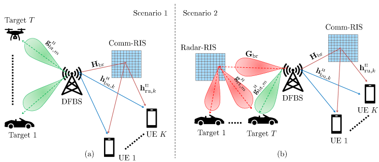
Consider an RIS-assisted MIMO ISAC system with a DFBS communicating with single antenna users and simultaneously transmitting radar waveforms towards point targets in the far field of the DFBS and RIS. The DFBS has a uniform linear array (ULA) with antennas, which transmits both communication symbols and radar waveforms. We assume that the targets and users are spatially well separated with the comm-RIS (the radar-RIS) located closer to the UEs (respectively, the targets) as illustrated in Fig. 1. Hence, the wireless links between the comm-RIS (the radar-RIS) and the targets (respectively, the UEs) are very weak, and effect of the corresponding wireless channels on the system can be safely ignored. The first setting is well suited when the targets are directly visible to the DFBS via a direct path, like for aerial surveillance or for environments with limited scattering. On the other hand, the second setting is suited for scenarios where the direct path to the targets is blocked or very weak, e.g., localization of cars or pedestrians in an urban setting, i.e., for environments with rich scattering.
II-A Downlink transmit signal model
Let denote the discrete-time baseband radar waveforms at time instance . We define the discrete-time complex baseband downlink communication symbols transmitted to the UEs as . We precode with the communication beamformer and precode using the sensing beamformer . The precoded radar waveforms and communication symbols are superimposed and transmitted from the DFBS. The complex baseband signal transmitted by the DFBS is
| (1) |
We assume that the UEs do not cooperate with each other and hence the communication symbols transmitted towards different UEs are assumed to be uncorrelated. We also assume that the radar and communication symbols are uncorrelated with each other and have unit power, i.e., , , and . Thus, the transmit signal covariance matrix is given by
| (2) | ||||
where we have introduced the rank-1 matrix .
II-B RIS model
We model the RIS as a collection of discrete passive phase shifters, which can be individually controlled from the DFBS via a low-rate control link. Specifically, we assume that the RIS comprises elements and model its spatial response as that of a uniform rectangular array (URA). The phase shifts of the RIS are collected in the vector , where denotes the phase shift introduced by the th RIS element. Here, with and denoting the comm-RIS and radar-RIS, respectively.
In the first setting, the RIS empowers only the communication part of ISAC, wherein the transmit signal reaches the UEs via a direct and an indirect path through the RIS and the transmit signal reaches the target only via a direct path. In the second setting, we have a dual-RIS setup with one RIS dedicated to sensing and one to communications. In the second setting, in addition to both users and targets receiving signals via the direct path, users (targets) also receive signal through the comm-RIS (respectively, the radar-RIS).
II-C Communication channel model
We consider a multi-user MIMO setting in which the DFBS communicates with single antenna UEs. Let denote the MIMO channel matrix for the DFBS-comm-RIS link. Let and denote the multiple input single output (MISO) channel vectors of the th UE corresponding to the DFBS-UE and RIS-UE links, respectively. The overall channel vector comprising of the direct link and the additional link via the RIS is given by
| (3) |
The signal received at the th UE is then
| (4) |
where is the additive Gaussian receiver noise having zero mean and variance .
II-D Radar channel model
Let denote the angular location of the th target with respect to (w.r.t.) the DFBS. Then the DFBS-target channel for the th target is modeled as an LoS channel and is given by
| (5) |
where is the complex path gain and is the array response vector of the DFBS. We denote the channel from the radar-RIS to the th target by . The overall channel between the DFBS and the th target is then
| (6) |
where is the channel between the DFBS and radar-RIS. Whenever the radar-RIS is not used or available, we simply set to zero.
III Problem formulation
The performance of an ISAC system is characterized by the communication and radar sensing metrics, which are used to design the transmit beamformers and the RIS reflection patterns.
III-A Communications metric
The quality of service for the multi-user MIMO communication system is determined by the spectral efficiency or rate of the UEs. For multi-user MIMO systems, the spectral efficiency or rate of the UEs is determined by the SINR at each user. To ensure a minimum SINR for all the UEs, we consider the worst-case SINR or the so-called fairness SINR as the communication metric.
To arrive at an expression for the SINR, let us express the received signal at the th UE, i.e., (4) as
where the first term corresponds to the intended symbol received at the th UE, the second term corresponds to the interference arising from the communication symbols intended for other UEs, and the third term corresponds to the interference arising from radar waveforms. Thus, the SINR for the th UE is a function of and is given by
| (7) |
with the worst-case SINR
| (8) |
III-B Radar sensing metrics
Next, we describe sensing performance metrics that we use for the two scenarios: when we do not use radar-RIS and when we use radar-RIS.
III-B1 Beampattern matching and cross-correlation error
A MIMO radar system detects and tracks targets by transmitting signals in certain desired directions. This is achieved by designing multiple beams that match a desired beampattern while keeping the correlation between different beams as small as possible [13, 10].
To ensure that sufficient power reaches different target locations, we need to choose a desired pattern that has main beams pointing in the direction of different targets. Furthermore, the comm-RIS is useful only if sufficient power reaches the comm-RIS in the first place. Thus, the desired pattern should also form a beam towards the direction of the comm-RIS from the DFBS, denoted by . Hence, the desired pattern is chosen to be a superposition of multiple rectangular beams of width degrees with centers around and as
| (9) |
The power radiated from the DFBS towards the direction is given by
| (10) |
For a desired beampattern , the beampattern mismatch error evaluated over a discrete grid of angles is a function of and is given by
| (11) |
where is the unknown autoscale parameter. The cross-correlation of the signals reflected back by the targets at directions and is given by
with the average squared cross-correlation being
| (12) |
We design radar beams that minimize a weighted sum of beampattern mismatch error and the average squared cross-correlation [13]
| (13) |
where and are the known weights that determine the relative importance of the two terms.
III-B2 Worst-case target illumination power
Whenever the direct paths between the DFBS and the targets are weak or blocked, forming multiple beams at the DFBS towards different targets by adopting a beampattern mismatch criterion will not be useful as the target illumination power will be very small. To enable sensing in such scenarios, radar-RIS can be used. However, due to the fully passive nature of the RIS, obtaining cross-correlation optimal beams directed towards targets is not possible. Therefore, we adopt an alternative metric and propose to maximize the worst-case target illumination power to design the sensing beamformers.
The power of the signal received at the th target corresponding to the transmitted waveform is . The worst-case target illumination power is given by
| (14) |
where and depends on through [c.f. (6)].
III-C Design problems
We now introduce the problems of designing the transmit beamformers at the DFBS and the RIS phase shifts for the two settings. For the setting [cf. Fig. 1(a)] with the comm-RIS assisting DFBS in communicating with multiple users, we design the transmit beamformers () and the comm-RIS phase shifts by minimizing the sensing cost function (13) while ensuring a minimum SINR for all users. For the setting [cf. Fig. 1(b)], we propose to design the transmit beamformers () and the radar- and comm-RIS phase shifts and , to maximize the worst-case target illumination power [cf. (14)] while ensuring a minimum SINR for all the users. We mathematically formulate the design problem in the first setting as
| (15a) | ||||
| (15b) | ||||
| (15c) | ||||
| (15d) | ||||
and the second setting as
| (16a) | ||||
| (16b) | ||||
| (16c) | ||||
| (16d) | ||||
where is the total transmit power with (15b) and (16b) denoting the power constraint per antenna element, is the SINR requirement of each user, and recall that is the autoscale parameter. The constraints (15d) and (16d) are due to the fact that the RIS is fully passive and can only reflect (i.e., phase shift) the incident signal to different directions. The optimization problem (15) is non-convex because of the quadratic equality in (15a), fractional term in (15c), and unit-modulus constraint in (15d).
In contrast to , we use a different objective function in . In addition to the design of the transmit beamformers and comm-RIS phase shifts, we also design the radar-RIS phase shifts in (). Optimization problem is also non-convex because of the quadratic equality (16a), fractional term in the constraint (16c), and unit-modulus constraints (16d).
IV Proposed solvers
In this section, we develop the proposed solvers for and .
IV-A Proposed solver for
Problem to design the transmit beamformers and comm-RIS phase shifts is not convex in the variables. Therefore, we propose to solve the optimization problem by alternatingly optimizing the beamformers and the autoscale parameter (i.e., ) while keeping the phase shifts (i.e., ) fixed, and vice versa. Specifically, in the first subproblem, we fix the comm-RIS phase shifts and design the beamformers to minimize the beampattern mismatch error while ensuring a minimum SINR for the users. Next, keeping the beamformers fixed, we optimize the comm-RIS phase shifts to maximize the worst-case SINR for all the UEs.
We repeat the aforementioned steps till convergence.
IV-A1 Updating , and , given
Let us now consider the subproblem of designing the beamformers and by fixing comm-RIS phase shifts for an appropriately selected SINR threshold . That is, we solve [10]:
| (17) | ||||
| subject to | ||||
which is still a non-convex optimization problem. To solve (17), we use the procedure from [10], which is provided here for self containment. From (2) and (7), the SINR constraints can be expressed as
| (18) |
for . Thus the subproblem (17) can be equivalently written as
| subject to | ||||
| (19) |
By dropping the quadratic equality constraint and rank constraints, we obtain the following relaxed convex optimization problem
| subject to | ||||
| (20) |
which is a semi-definite quadratic program (SQP) that can be efficiently solved using off-the-shelf solvers.
Let us call the solution of (20) as . Now we compute the beamformers as
| (21) |
and using the Cholesky decomposition as
| (22) |
By construction, satisfies the SINR constraints as . Since and
for any due to the Cauchy-Schwartz inequality, we have Thus, also form a feasible solution to (20). Further, the constructed solution does not change the objective value, and thus will yield the smallest objective value for (20).
IV-A2 Updating , given , , and
The subproblem of finding the comm-RIS phase shifts, given , , and , simplifies to the feasibility problem
| (23) |
However, the fixed choice of in (17) is already a solution to the above problem. Since different choices of lead to different achievable SINRs at the UEs, i.e., better , we can alternatively design to improve the achievable SINR at the UEs by solving
| (24) |
where . Due to the unit modulus constraint and the fractional nature of the cost function, (24) is a non-convex optimization problem in and its exact solution is difficult to compute.
To solve (24), we first express it as a generalized linear fractional program with multiple ratios by expressing the SINR explicitly in terms of . Define the vectors and of length . Let us also define the square matrices and of size . From (3), we can then express SINR in (7) as
| (25) |
where . By letting , we rewrite (24) as
| (26) |
where we have introduced a less restrictive and convex semi-definite constraint on instead of the rank one constraint. The problem in (26) is a generalized linear fractional program with a convex constraint set. Next, we develop an iterative procedure to solve (26) using the generalized Dinkelbach-type method [34], which is guaranteed to converge to the solution of (26).
Let us denote the iterate at step as . We first compute an estimate of the worst-case SINR as
| (27) |
Next, we update as
| (28) |
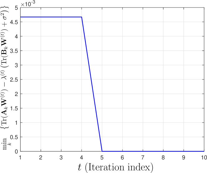
where and
at optimality. This condition can be used to stop the iterations (see Fig. 4). In practice, we may update and till , where Tol is the tolerance value.
Let us denote the solution from this iterative procedure as . To recover a rank-1 solution from , we use Gaussian randomization [35]. That is, we generate realization of complex Gaussian random vectors with zero mean and covariance matrix . We then normalize to obtain unit modulus vectors with entries
We choose the realization that results in the largest worst-case SINR as
| (29) |
and the optimal comm-RIS phase shift as for . The actual worst-case SINR corresponding to the rank-1 solution obtained from this Gaussian randomization will be in the interval and .
IV-A3 Practical considerations for choosing
Let us denote , and at the th iteration as , , and , respectively. Since we have more degrees of freedom in choosing in the relaxed problem (26) than with a unit modulus (or rank) constraint as in (24), we have , in general. In other words, the achievable SINR is much higher if we ignore the passive nature of the RIS, but is not practically realizable. At each iteration, we can only evaluate and , but we cannot compute .
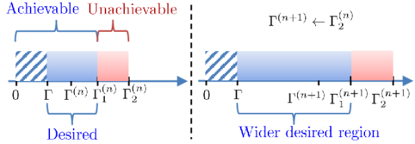
To design the beamformers and the comm-RIS phase shifts, starting from an initial comm-RIS phase shift, we update and using (21) and (22), respectively. Then, we update as in (29). Specifically, in the th iteration, we solve (20) with the desired SINR set to . We repeat the alternating optimization until , where recall that is the actual SINR that can be achieved after Gaussian randomization. We refer to the interval as the achievable region. The interval with values of SINR that are both achievable and desired, i.e., the interval between and is referred to as the desired region. Whenever the width of the desired region is small, it is less likely that the Gaussian randomization procedure (described in the previous subsection) produces realization in the desired region. Therefore, it is possible to have , thereby violating the communication SINR requirements. A narrow desired region, in other words, indicates that the RIS phase shifts alone cannot significantly improve the SINR of UEs. At the same time, a higher SINR is often achievable by designing beamformers since we have higher flexibility (i.e., without unit modulus constraints). To circumvent this issue, in the th iteration, we design the beamformers so as to achieve an SINR higher than by setting , thereby increasing the width of the desired region. With a widened desired region, it is more likely that Gaussian randomization produces realization with as desired. This is illustrated in Fig. 2. The proposed procedure for solving is summarized as Algorithm 1.
IV-A4 Computational complexity
For an -accurate solution, the worst-case complexity for computing the beamformers, given the RIS phase shifts is that of an SDP with constraints and is of the order of about [10]. For the subproblem of computing the RIS phase shifts, given the beamformers, we solve an SDP for Dinkelbach-like iterations in the inner loop. Thus, the complexity involved in obtaining the RIS phase shifts given the beamformers is of the order of about . Suppose be the number of iterations in the outer loop of the proposed alternating optimization algorithm. Then, the overall complexity is about .
IV-B Proposed solver for
We next develop a solver to design the transmit beamformers and the phase shifts of both the radar-RIS and comm-RIS, i.e., we present a solver for Problem . As before, we adopt an alternating optimization based procedure to solve the non-convex optimization problem (), wherein we design the beamformers while keeping the phase shifts fixed and vice versa.
IV-B1 Updating and , given and
Given and , simplifies to a problem with exactly the same constraints as (20), but with a different objective function, i.e., we have
| subject to | ||||
| (30) |
where we have replaced the SINR constraint in with an equivalent inequality in (18) and dropped the rank one constraint on as we did from (19) to (20). A rank-1 solution and is obtained using (21) and (22), respectively, after solving the above convex program. The constructed solution will yield the largest objective value for (30).
For a fixed and , the subproblems of finding and are independent of each other and can be solved separately.
IV-B2 Updating , given and
IV-B3 Updating , given and
We now discuss the design of radar-RIS phase shifts, where we maximize the worst-case target illumination power , given the beamformers (, ).
From (6), we can express (14) explicitly in terms of as
where and and
To obtain the optimal phase shifts, we solve the following optimization problem:
| (31) | ||||
| subject to |
where we dropped the non-convex rank constraint () as before. The optimization problem (31) is convex and is then solved using off-the-shelf convex solvers. Let be the solution to (31). The required rank-1 solution is then extracted from using Gaussian randomization (refer to Sec. IV-A2).
To ensure that sufficient power is radiated towards different target directions, we initialize radar-RIS phase shifts so that equally powerful beams are formed towards all target directions. The selection and update of the target SINR at each iteration is as before. The proposed procedure to solve is summarized as Algorithm 2.
IV-B4 Computational complexity
Similar to the update of comm-RIS phase shifts, updation of radar-RIS phase shifts also involves solving an SDP with an associated complexity of . Hence, the overall complexity is about flops, which is of the same order as that of Algorithm 1.
V Numerical simulations
| Parameter | Value |
|---|---|
| DFBS location | m |
| comm-RIS location | m |
| radar-RIS location | m |
| Target angles w.r.t. DFBS | |
| Target distance from DFBS | m |
In this section, we present results from a number of numerical experiments to illustrate the benefits of RIS-enabled ISAC systems and performance of the proposed algorithms. Throughout the simulations, we model the DFBS as a ULA with half-wavelength spaced elements. Both the comm- and radar-RISs are modeled as URAs comprising of quarter-wavelength spaced elements [15]. We model the entries of the channels , , and for as Rician distributed random variables with a Rician factor of . The direct channel for the communication UEs, i.e., for is assumed to undergo Rayleigh fading. The remaining channels, namely, and for are modeled as LoS channels.
The receiver noise variance at the UEs is set to dBm. The targets are assumed to be located in the far-field of both the DFBS and radar-RIS. User locations are drawn randomly from a rectangular grid having corners m, m, m, and m. The pathlosses of radar-RIS and target links and DFBS and UE links are modeled as dB and dB , respectively. Pathlosses for the rest of the links are modeled as dB with being the distance between concerned terminals in m. Rest of the simulation parameters are presented in Table I.
V-A Comm-RIS assisted ISAC system
We begin by presenting the designed transmit beampattern and the reflection profile of the comm-RIS. Then we present results from the Monte-Carlo experiments to show the benefits of RIS in ISAC systems in terms of the achievable SINR and worst-case illumination power at the target locations of interest by varying different system parameters such as SINR requirement (), number of RIS elements (), and number of users with direct path (). In this section, we consider a two-target scenario, i.e., with and .
We compare the performance of the proposed method in terms of transmit pattern, the fairness SINR (or min-rate), and the worst-case target illumination power with the following four schemes: (i) joint active and passive beamforming design (JAPBD) in [32], (ii) RIS manual selection, wherein we select the RIS phase profile to form equally powerful beams towards all the UEs, and (iii) no RIS, wherein we consider an ISAC system without RIS [10]. We compute the beamformers at the DFBS by solving (20) for both RIS manual selection and no RIS schemes. Although such manual selection of RIS phase shifts seem intuitive, they are agnostic to the task at hand and are not fairness SINR optimal. We also compare the proposed method with (iv) sensing-only system, which does not have any communication functionality or RIS [13]. For the sensing-only system, we solve only w.r.t. ( is set to zero) without the constraints (15c) and (15d). To simulate different schemes, we first run JAPBD to compute the minimum total transmit power required to achieve certain radar SNR, communication SINR, and average squared cross-correlation between the beams. We then choose the resulting power as the total power constraint for the remaining schemes, thereby ensuring that all schemes utilize the same amount of transmit power.
V-A1 Transmit beampattern and RIS reflection pattern
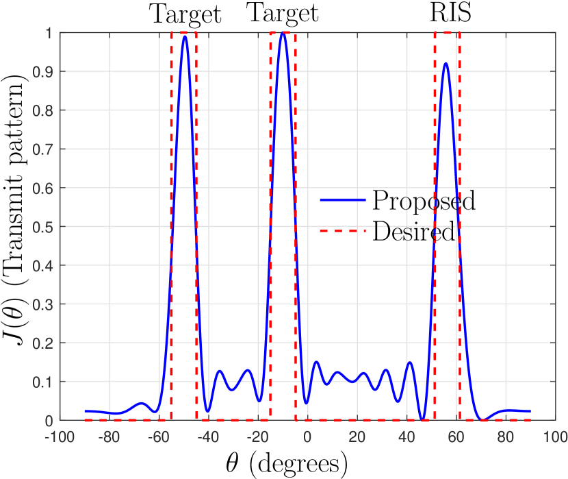
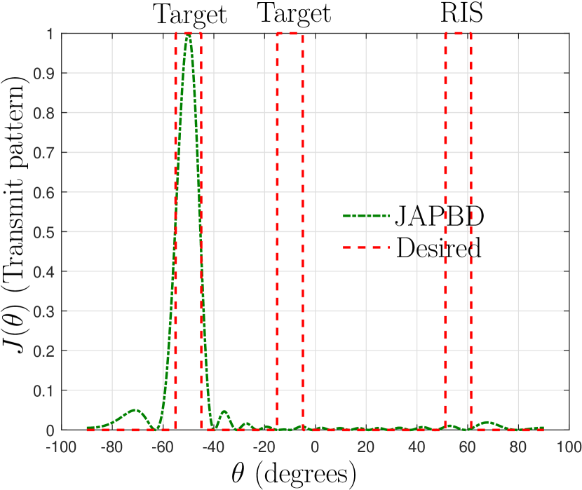
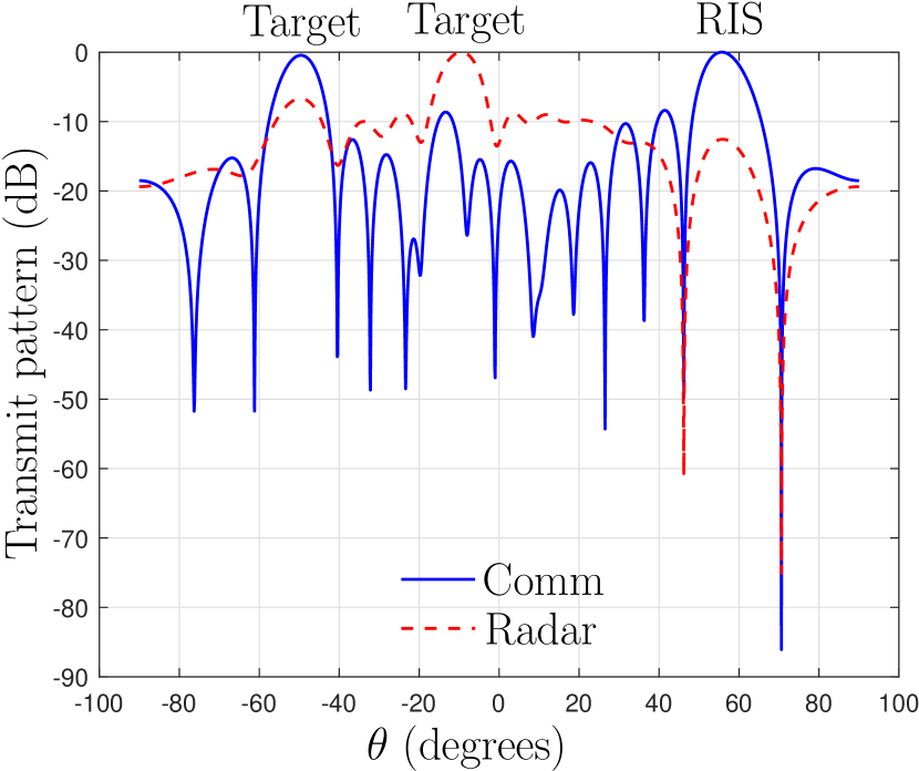
For the ideal beampattern in (9), we use a superposition of rectangular box functions of width degrees. We set in [cf. (13)]. To illustrate the beampattern obtained from Algorithm 1, we consider . We use RIS elements and . The transmit beampattern at the DFBS is shown in Fig. 3(a) and 3(b). The transmit pattern of a scheme that considers sum received SNR as the radar metric [32] results in a peak only towards one of the targets. As a consequence, a system designed using the metric presented in [32] completely misses one of the targets. On the other hand, the transmit beampattern of the proposed algorithm has a response towards the two target locations of interest as well as towards the comm-RIS, as desired, thereby ensuring that none of the targets are missed.
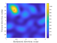
To gain further insights, we consider individual beampatterns of the radar and communication beamformers, where the radar beampattern is defined as and the beampattern related to the th communication user is defined as To visualize the reflection pattern at RIS, we define the beampattern of RIS towards the direction cosine vector for a signal incident on the RIS from the DFBS from the direction as follows where is the array response vector of the RIS. The separate beampatterns (related to the sensing and communication beamformers) at the RIS is shown in Fig. 3(c). We observe that the radar beam has peaks towards target directions of interest and the communication beam has a stronger peak towards the RIS. Further, the radar beam has a dip in the direction of the RIS. This is desired since the comm-RIS is used solely to serve the UEs, and any amount of radar signals transmitted towards the UEs via the RIS could lead to potentially increased interference (hence lower SINR) at the communication UEs. While transmitting radar signals to communication UEs leads to interference, transmitting communication signals (known at the DFBS) to target locations actually helps in improving the target illumination power, and this explains the peaks of communication beams towards the targets. In Fig. 3(d), we show the reflection pattern of the RIS, where we can see that the RIS beampattern has a peak towards the user direction. This is intuitive since the RIS attempts to steer all the energy incident on it towards the single UE to maximize the received SINR. For larger values of , unlike the case, the reflection pattern at the RIS is often not interpretable as the SINR optimal design is not necessarily the pattern that forms beams towards users.
V-A2 Monte-Carlo simulations
We now consider a multi-user, multi-target scenario with , , and , unless mentioned otherwise. We present a number of results from Monte-Carlo experiments that are obtained by averaging over 100 independent realizations of the fading channel with different user locations. Unless mentioned otherwise, we use radar SNR requirement of dB and a average squared cross-correlation of .
In Fig. 5(a), we show the impact of SINR constraint () on the fairness SINR of different methods. While the benchmark schemes provide exactly the minimum required SINR, the proposed method provides significantly high SINR, without consuming any additional power. This is due to the fact that the selection of comm-RIS phase shifts is carried out to maximize the SINR itself, unlike the other schemes. Impact of on the worst-case target illumination power is presented in Fig. 5(b). The worst-case target illumination power of JAPBD is significantly less than that of other schemes. This happens due to the choice of sum radar SNR as the performance metric in JAPBD which results in scenarios like the one presented in Fig. 3(a) wherein not all targets are illuminated. On the other hand, due to the use of a weighted sum of beampattern mismatch error and average squared cross-correlation as the radar metric, the radar performance of the rest of the schemes are much higher than that of JAPBD. Moreover, performance of the proposed scheme is also comparable to that of a sensing-only system, which is the benchmark method since an ISAC system cannot achieve better sensing performance than a comparable sensing-only system. The worst-case target illumination power of the proposed method is only about dB worse than that of an ISAC system without the RIS. This degradation is due to the fact that we form a beam towards the RIS in addition to the beams towards the target directions of interest. We can also observe that the worst-case target illumination power of no RIS and sensing-only system are comparable as these do not form any beam towards the RIS.
In Fig. 5(c) and Fig. 5(d), we present the communication and radar performance of different methods for varying number of RIS elements. As before, SINR of the proposed method is significantly higher than that of other benchmark schemes. The worst-case target illumination power of the proposed scheme is also remarkably better than that of JAPBD and is comparable to that of the benchmark scheme sensing-only system. The fairness SINR of the proposed method also increases with an increase in the number of comm-RIS elements due to the increased array gain offered by the RIS. On the other hand, since the comm-RIS is not involved in sensing, changes in will not affect the worst-case target illumination power. Albeit a moderate loss of about dB in due to the formation of an additional beam towards the RIS, the fairness SINR is significantly improved, often by more than dB by properly designing the phase profile of the comm-RIS.
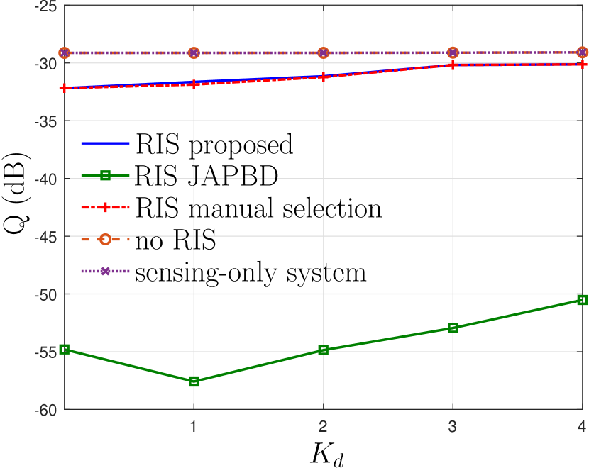
Next, we consider a setting where only out of users have a direct path from the DFBS and the direct paths to the remaining UEs are blocked. For the considered scenario, an ISAC system without RIS would only be able to serve users out of . We show the minimum-rate, i.e., and the worst-case target illumination power for different number of UEs with direct path, i.e., , in Fig. 5(e) and Fig. 5(f), respectively. We can see that with the comm-RIS, all the users, irrespective of the presence of a direct path or not, is guaranteed a minimum SINR of (or min-rate of 2.05 bps/Hz). However, without the RIS, only users are served with an SINR higher than . Although RIS manual selection and JAPBD also offer a min-rate of bps/Hz, the proposed method offers a significantly higher min-rate of about bps/Hz. As before, the value of of ISAC systems with RIS degrades by about dB compared to an ISAC system without RIS. We wish to re-emphasize that JAPBD often results in scenarios where not all targets are properly illuminated, leading to low values of the worst-case target illumination power, as indicated in Fig. 5(f). On the other hand, the proposed scheme ensures that all targets are illuminated with sufficient power even when the direct path to a few of the users is blocked. Throughout the simulations, we have also observed (not shown here) that the mean squared cross-correlation of the proposed method is comparable, often better, than that of JAPBD scheme.
V-B Dual RIS-assisted ISAC system
In this subsection, we demonstrate the advantages of using dedicated RISs for sensing and communications in an ISAC system. We assume that two identical RIS with elements assist the communication and sensing functionalities of the ISAC system. We use the same simulation parameters as before and the parameters are provided in Table I. Unless otherwise mentioned, we use , , , , and .
Let us recall that the dual RIS-assisted ISAC system is particularly suited for scenarios where some or all of the targets are not directly visible to the DFBS. Let denote the number of targets that are directly visible to the DFBS. In this section, we present the fairness SINR (or min-rate) and the worst-case target illumination power of different schemes for varying simulation parameters such as SINR constraints (), number of RIS elements (), number of users with direct path , and the number of targets that are directly visible to the DFBS (). All the results in this subsection are obtained by averaging over 100 independent channel realizations with varying user locations.
As before, we compare the performance of the proposed method, i.e., RIS proposed, with that of manually designing beams at each RIS. Specifically, we select the radar-RIS (respectively, comm-RIS) phase shifts to form equally powerful beams towards all the targets locations of interest (respectively, all UEs). The transmit beamformers are then obtained by solving (20). We consider four different scenarios of ISAC systems for comparison: dual RIS with manually selected phase shifts to form interpretable beams, indicated as manual selection (both RISs); only single radar-RIS with manually designed phase shifts, indicated as manual selection (only radar RIS); only single comm-RIS with manually designed phase shifts, indicated as manual selection (only comm RIS); and ISAC system without RIS, indicated as no RIS. The methods with manual selection of RIS phase shifts are agnostic to the considered task. In addition, we also use sensing-only system [13] as a baseline system for radar performance.
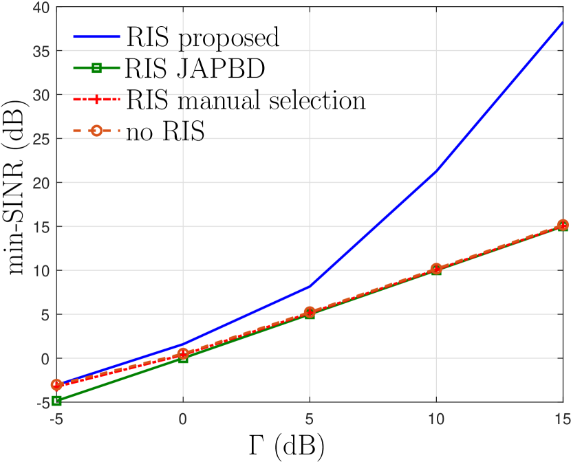
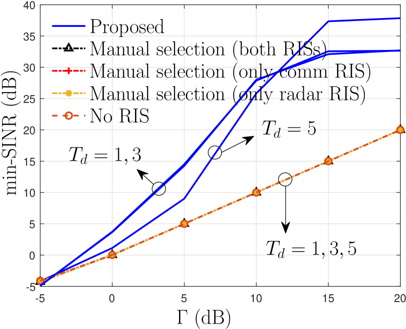
In Fig. 6(a), we present the fairness SINR of different methods. The proposed method clearly outperforms baseline systems based on manual selection of RIS phase shifts, ISAC system without RIS [10] and sensing-only system [13] while improving the fairness SINR by often more than dB, irrespective of whether all targets are directly visible to the DFBS or not. Since the precoder design phase attempts to maximize while satisfying the fairness SINR, the fairness SINR will be about . This is the reason why all the baseline methods achieve a fairness SINR of dB. However, in the proposed method, once the precoders and are designed, the comm-RIS phase shifts are also updated so as to maximize the SINR. This leads to a significantly high fairness SINR for the proposed scheme.
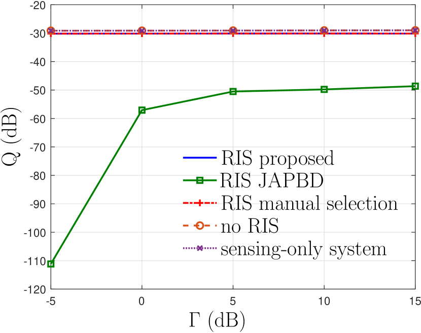
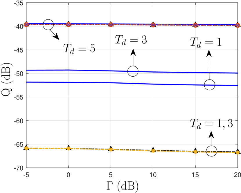
The worst-case target illumination power of different methods is presented in Fig. 6(b). As expected, schemes that do not utilize a dedicated radar-RIS are not able to illuminate all targets efficiently whenever a few targets (say, ) are not directly visible to the DFBS. While manual selection (only radar RIS) and manual selection (both RISs) results in a non-zero worst-case target illumination power, the proposed scheme offers more than dB higher than the next best benchmark scheme. As increase from to , the of the proposed method also increase by about 3 dB. This is expected since more number of targets can be now served directly via the DFBS. When all targets are visible to the DFBS (i.e., ), the performance of all methods are comparable with the proposed scheme offering a slight improvement. Furthermore, with an increase in the SINR requirement, of all schemes decrease. This is because of the higher amount of power that needs to be transmitted towards the UEs to meet the increased fairness SINR requirement.
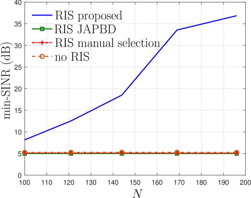
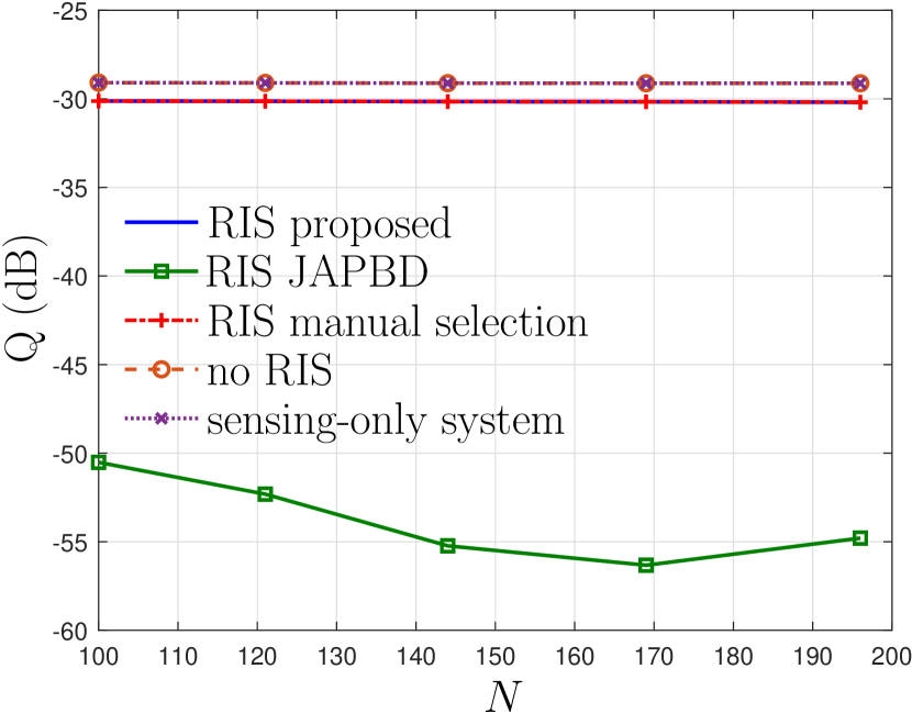
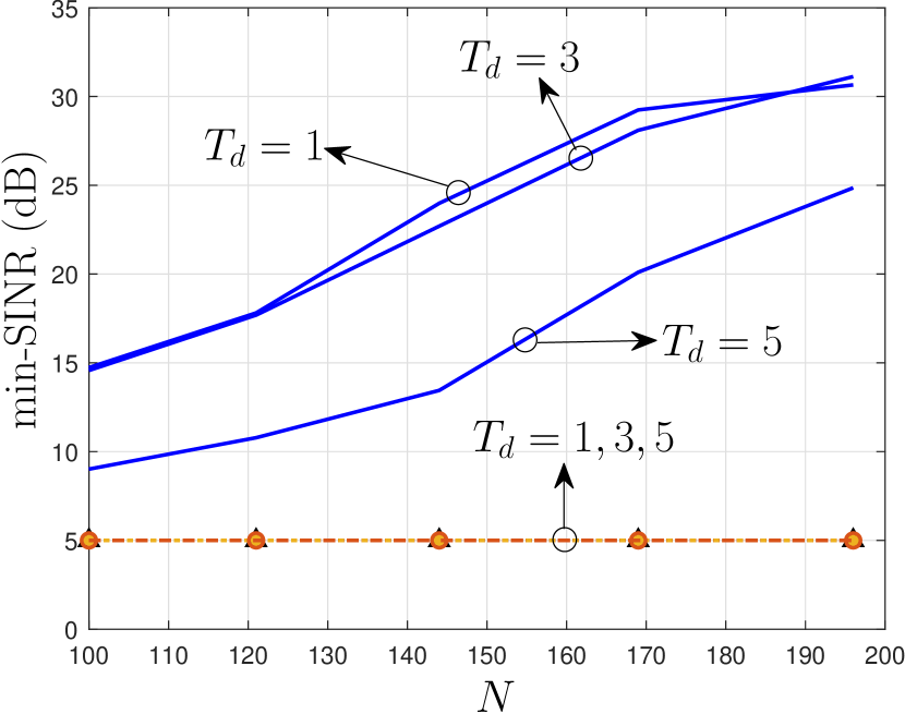
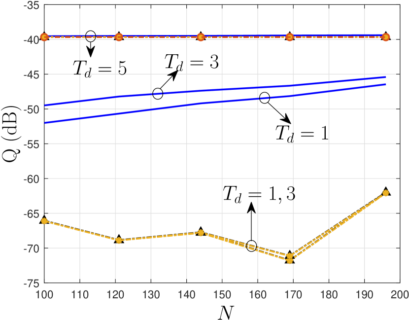
In Fig. 6(c) and Fig. 6(d), we illustrate the impact of number of RIS elements () on the fairness SINR and worst-case target illumination power, respectively. As before, irrespective of the number of targets with direct paths, the proposed scheme offers significant improvements in the fairness SINR over other benchmark schemes. Moreover, of the proposed method is also remarkably high when compared with schemes where the radar-RIS phase shifts are manually designed, especially when few of the targets are not directly visible to the DFBS. As the number of radar-RIS (respectively, comm-RIS) elements increase, the array gain offered by the radar-RIS (respectively, comm-RIS) also increase leading to an increase in the worst-case target illumination power (respectively, fairness SINR). Since the comm-RIS is not involved in radar sensing, of manual selection (only radar RIS) and manual selection (both RISs) overlap with each other. Similarly, both manual selection (only comm RIS) and no RIS also have identical values of because both these scenarios correspond to a setting without the radar-RIS.
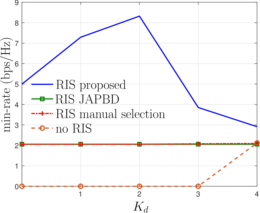
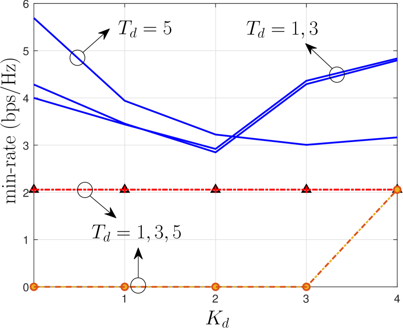
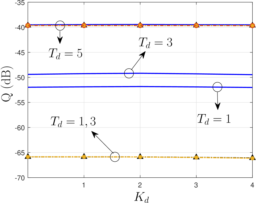
Finally, we show the performance of the proposed dual-RIS-assisted ISAC system in a scenario with the direct paths to a few of the users is blocked in Fig. 6(e) and Fig. 6(f). As before, with the use of the comm-RIS, all users are served with a minimum SINR of (i.e., min-rate of bps/Hz). Moreover, with the proposed scheme, all users are served with a higher rate irrespective of . As can be observed from Fig. 6(f), the proposed method results in remarkably improved worst-case target illumination powers, especially when the direct paths to a few of the targets are blocked. In sum, albeit the inability to form uncorrelated beams due to the fully passive nature of RISs, using an additional RIS for radar sensing along with the comm-RIS leads to significant improvements in both radar and communication performance of ISAC systems especially when not all targets are directly visible to the DFBS.
VI Conclusions
We considered two settings of RIS-assisted ISAC systems, namely, a setting with a single RIS that assists only the communication functionality of an ISAC system and a setting with two RISs wherein dedicated RISs are used for sensing and communications. We developed algorithms to design the transmit beamformers to jointly precode communication symbols and radar waveforms and to also design RIS phase shifts to achieve certain sensing performance in terms of the beampattern matching error or worst-case target illumination power while ensuring a minimum SINR for the communication UEs. Since the resulting optimization problems are non-convex, we have developed alternating optimization solvers for the design problems that appear in the two settings. A semi-definite convex problem is used to solve for transmit beamformers with fixed RIS phase shifts. With fixed transmit beamformers, the design of comm-RIS phase shifts is carried out using generalized Dinkelbach iterations. With fixed transmit beamformers, the design of radar-RIS phase shifts is carried out using SDP followed by Gaussian randomization. The performance of the proposed algorithms is then demonstrated through numerical simulations. Specifically, the comm-RIS assisted ISAC system is found to significantly improve the fairness SINR while suffering from a moderate loss in radar performance. On the other hand, the dual-RIS assisted ISAC system is found to remarkably improve both communication and radar performance metrics, especially in scenarios where all the targets are not directly visible to the DFBS.
References
- [1] N. Rajatheva et.al, “White paper on broadband connectivity in 6G,” arXiv preprint arXiv:2004.14247, Apr. 2020.
- [2] F. Liu, Y. Cui, C. Masouros, J. Xu, T. X. Han, Y. C. Eldar, and S. Buzzi, “Integrated sensing and communications: Towards dual-functional wireless networks for 6G and beyond,” IEEE J. Sel. Areas Commun., vol. 40, no. 6, pp. 1728–1767, Mar. 2022.
- [3] Henk Wymeersch et.al, “Integration of communication and sensing in 6G: a joint industrial and academic perspective,” arXiv preprint arXiv:2106.13023, Jun. 2021.
- [4] M. Nemati, Y. H. Kim, and J. Choi, “Toward joint radar, communication, computation, localization, and sensing in IoT,” IEEE Access, vol. 10, pp. 11 772–11 788, Jan. 2022.
- [5] K. V. Mishra, M. R. Bhavani Shankar, V. Koivunen, B. Ottersten, and S. A. Vorobyov, “Toward millimeter-wave joint radar communications: A signal processing perspective,” IEEE Signal Process. Mag., vol. 36, no. 5, pp. 100–114, Sept. 2019.
- [6] D. Ma, N. Shlezinger, T. Huang, Y. Liu, and Y. C. Eldar, “Joint radar-communication strategies for autonomous vehicles: Combining two key automotive technologies,” IEEE Signal Process. Mag., vol. 37, no. 4, pp. 85–97, Jul 2020.
- [7] A. R. Chiriyath, B. Paul, and D. W. Bliss, “Radar-communications convergence: Coexistence, cooperation, and co-design,” IEEE Trans. Cogn. Commun. Netw., vol. 3, no. 1, pp. 1–12, Mar. 2017.
- [8] L. Zheng, M. Lops, Y. C. Eldar, and X. Wang, “Radar and communication coexistence: An overview: A review of recent methods,” IEEE Signal Process. Mag., vol. 36, no. 5, pp. 85–99, Sep. 2019.
- [9] F. Liu, C. Masouros, A. P. Petropulu, H. Griffiths, and L. Hanzo, “Joint radar and communication design: Applications, state-of-the-art, and the road ahead,” IEEE Trans. Commun., vol. 68, no. 6, pp. 3834–3862, Feb. 2020.
- [10] X. Liu, T. Huang, N. Shlezinger, Y. Liu, J. Zhou, and Y. C. Eldar, “Joint transmit beamforming for multiuser MIMO communications and MIMO radar,” IEEE Trans. Signal Process., vol. 68, pp. 3929–3944, Jun. 2020.
- [11] F. Liu, Y.-F. Liu, A. Li, C. Masouros, and Y. C. Eldar, “Cramér-rao bound optimization for joint radar-communication beamforming,” IEEE Trans. Signal Process., vol. 70, pp. 240–253, Dec. 2021.
- [12] J. Pritzker, J. Ward, and Y. C. Eldar, “Transmit precoder design approaches for dual-function radar-communication systems,” arXiv preprint arXiv:2203.09571, Mar. 2022.
- [13] P. Stoica, J. Li, and Y. Xie, “On probing signal design for MIMO radar,” IEEE Trans. Signal Process., vol. 55, no. 8, pp. 4151–4161, Jul. 2007.
- [14] E. Basar, M. Di Renzo, J. De Rosny, M. Debbah, M. Alouini, and R. Zhang, “Wireless communications through reconfigurable intelligent surfaces,” IEEE Access, vol. 7, pp. 116 753–116 773, Aug. 2019.
- [15] M. Di Renzo, A. Zappone, M. Debbah, M.-S. Alouini, C. Yuen, J. de Rosny, and S. Tretyakov, “Smart radio environments empowered by reconfigurable intelligent surfaces: How it works, state of research, and the road ahead,” IEEE J. Sel. Areas Commun., vol. 38, no. 11, pp. 2450–2525, July 2020.
- [16] H. Wymeersch and B. Denis, “Beyond 5G wireless localization with reconfigurable intelligent surfaces,” in Proc. of the IEEE Int. Commun. Conf. (ICC), Dublin, Ireland, Jun. 2020.
- [17] S. Buzzi, E. Grossi, M. Lops, and L. Venturino, “Foundations of MIMO radar detection aided by reconfigurable intelligent surfaces,” IEEE Trans. Signal Process., vol. 70, pp. 1749–1763, Mar. 2022.
- [18] F. Wang, H. Li, and J. Fang, “Joint active and passive beamforming for IRS-assisted radar,” IEEE Signal Process. Lett., vol. 29, pp. 349–353, Dec. 2021.
- [19] W. Lu, B. Deng, Q. Fang, X. Wen, and S. Peng, “Intelligent reflecting surface-enhanced target detection in MIMO radar,” IEEE Sens. Lett., vol. 5, no. 2, pp. 1–4, Jan. 2021.
- [20] X. Shao, C. You, W. Ma, X. Chen, and R. Zhang, “Target sensing with intelligent reflecting surface: Architecture and performance,” IEEE J. Sel. Areas Commun., early access, Mar. 2022.
- [21] Z. M. Jiang, M. Rihan, P. Zhang, L. Huang, Q. Deng, J. Zhang, and E. M. Mohamed, “Intelligent reflecting surface aided dual-function radar and communication system,” IEEE Syst. J., pp. 1–12, Feb. 2021.
- [22] Y. He, Y. Cai, H. Mao, and G. Yu, “RIS-assisted communication radar coexistence: Joint beamforming design and analysis,” IEEE J. Sel. Areas Commun., early access, Mar. 2022.
- [23] X. Song, D. Zhao, H. Hua, T. X. Han, X. Yang, and J. Xu, “Joint transmit and reflective beamforming for IRS-assisted integrated sensing and communication,” in Proc. of the IEEE Wireless Communications and Networking Conference (WCNC), Austin, TX, USA, May 2022.
- [24] R. S. P. Sankar, B. Deepak, and S. P. Chepuri, “Joint communication and radar sensing with reconfigurable intelligent surfaces,” in Proc. of the IEEE Int. Wrksp. on Signal Process. Adv. Wireless Commun. (SPAWC), Lucca, Italy, Sep. 2021.
- [25] R. Liu, M. Li, and A. L. Swindlehurst, “Joint beamforming and reflection design for RIS-assisted ISAC systems,” arXiv preprint arXiv:2203.00265, Mar. 2022.
- [26] Y. Li and A. Petropulu, “Dual-function radar-communication system aided by intelligent reflecting surfaces,” arXiv preprint arXiv:2204.04721, Apr. 2022.
- [27] R. Liu, M. Li, Y. Liu, Q. Wu, and Q. Liu, “Joint transmit waveform and passive beamforming design for RIS-aided DFRC systems,” IEEE J. Sel. Topics Signal Process., early access, May 2022.
- [28] X. Wang, Z. Fei, Z. Zheng, and J. Guo, “Joint waveform design and passive beamforming for RIS-assisted dual-functional radar-communication system,” IEEE Trans. Vehicular Tech., vol. 70, no. 5, pp. 5131–5136, May 2021.
- [29] X. Wang, Z. Fei, J. Huang, and H. Yu, “Joint waveform and discrete phase shift design for RIS-assisted integrated sensing and communication system under Cramer-Rao bound constraint,” IEEE Trans. Vehicular Tech., vol. 71, no. 1, pp. 1004–1009, Jan. 2022.
- [30] Z. Zhu, Z. Li, Z. Chu, G. Sun, W. Hao, P. Xiao, and I. Lee, “Intelligent reflecting surface assisted integrated sensing and communications for mmWave channels,” arXiv preprint arXiv:2202.00552, Jan. 2022.
- [31] E. Shtaiwi, H. Zhang, A. Abdelhadi, and Z. Han, “Sum-rate maximization for RIS-assisted radar and communication coexistence system,” in Proc. of the IEEE Global Commun. Conf. (GLOBECOM), Madrid, Spain, Dec. 2021.
- [32] M. Hua, Q. Wu, C. He, S. Ma, and W. Chen, “Joint active and passive beamforming design for irs-aided radar-communication,” arXiv preprint arXiv:2203.14532, Mar. 2022.
- [33] W. Dinkelbach, “On nonlinear fractional programming,” Management Science, vol. 13, no. 7, pp. 492–498, Mar. 1967.
- [34] J.-P. Crouzeix and J. A. Ferland, “Algorithms for generalized fractional programming,” Mathematical Programming, vol. 52, pp. 191–207, May 1991.
- [35] Z.-Q. Luo, W.-K. Ma, A. M.-C. So, Y. Ye, and S. Zhang, “Semidefinite relaxation of quadratic optimization problems,” IEEE Signal Process. Mag., vol. 27, no. 3, pp. 20–34, May 2010.