A Note on Low-Pass Filter Conditioning
for Current-Mode Control
Abstract
Low-pass filter is a classic control conditioning approach for high frequency current-mode control. However, no existing literature discusses the large-signal stability criterion for the current-mode control with low-pass filters. This paper provides a mathematically rigorous large-signal stability criterion. The result can directly benefit the practical engineering implementation of the low-pass filter in high-frequency current-mode control.
I Introduction
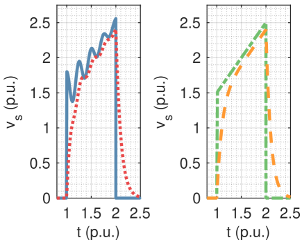
Low-pass filters, the traditional way to signal condition the interference, stabilize the current control loop by attenuating the amplitude of interference. However, as shown in Fig. 1, the actual inductor current may be distorted. Low-pass filters are traditionally not recommended to cut off before the switching frequency; however, this makes the filters unable to effectively suppress the interference whose spectrum is near or below the switching frequency. Because of our results on the robustness of peak current-mode control, we can allow the cut-off frequency of filters to be well below the switching frequency and still have good performance.
II System description
We take constant off-time current-mode control as an example. The current control loop using constant off-time can be modeled as
| (1) |
where is the convolution operator, is the impulse response function of the low-pass filter, is the zero input response of filter, and is the unit step function. Equation (1) captures the low-pass filter response. The variable represents the current sensor output and filter input;
can be expressed as the additive summation of the inductor current on the bottom switch and interference
| (2) |
We exemplify this idea with a first-order low-pass filter with the impulse response function and , where represents the time constant. A continuous static mapping is a prerequisite for stability. Theorem 1 provides a sufficient condition for the filter to guarantee a continuous static mapping. As long as the time constant satisfies Theorem 1, the static mapping is continuous. We denote the lower bound of the frequency of interference by .
Theorem 1.
A current control loop using constant off-time has minimum on time and off time . The time constant of the first-order low-pass filter is . The interference is amplitude and bandwidth-limited. The condition for to guarantee a continuous static mapping is
| (3) |
where
| (4) |
Proof.
II-A Continuity Theorem for General Linear Filter
The continuous static mapping is equivalent to the monotonic current sensor output. Therefore, the continuity condition can be equivalently expressed as
| (5) |
for all .
For all , and are differentiable
| (6) | ||||
| (7) |
The zero state response of the filter given input signal is
| (8) |
where is the forced response and the rest is natural response. We denote the forced response as . For all , is differentiable
| (9) |
By substituting (6), (7), (9) into (5), the continuity condition for the static mapping can be equivalently expressed as
| (10) |
II-B Continuity Theorem for First-Order Low-Pass Filter
For a first-order low-pass filter with time constant , the impulse response and zero input response
| (11) |
The frequency response function of the filter is
| (12) |
From (11) and (12), we can bound from the top as
| (13) |
| (14) |
| (15) |
| (16) |
| (17) |
In the worst-case, . We substitute (14) and (II-B) into (5). When , (5) can be bounded from below by
| (18) |
where , and . As long as we impose a positive lower bound for (18), the static mapping is continuous. The proof is complete.
∎
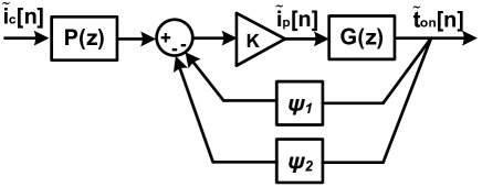
We next examine how the filter affects the stability of the current control loop. At the operating point defined by the desired peak inductor current , the actual peak inductor current , the actual valley inductor current , at on time , we linearize system (1) as
| (19) |
where
| (20) |
System (II-B) is represented by the block diagram in Fig. 2(a). The detailed derivations are provided in Appendix A.
The gain term , pole-zero pair, and feedback gains and are introduced as
| (21) |
| (22) |
| (23) |
| (24) |
Theorem 2 provides the condition for so that the current control loop is globally asymptotically stable. If satisfies the condition, the globally asymptotic stability is guaranteed.
Theorem 2.
A current control loop using constant off-time has a minimum on time and fixed off time . The time constant of the first-order, low-pass filter is . The interference is amplitude and bandwidth limited. The bound on to guarantee the globally asymptotic stability of the current control loop is
| (25) |
and
| (26) |
where
| (27) |
Proof.

The current control loop with filter can be modeled as the block diagram in Fig. 3, where
| (28) | ||||
| (29) | ||||
| (30) |
From the small gain theorem,
| (31) |
is defined as
| (32) |
The nonlinear subsystem follows
| (33) |
We can find the gain of the subsystem and as
| (34) | ||||
| (35) |
We can find the gain of the nonlinear function by evaluating its derivatives
| (36) |
where
| (37) | ||||
| (38) | ||||
| (39) |
can be bounded from above as
| (40) |
To bound , we have the following relationship of , and in transition as
| (41) |
We substitute (II-B) into (38)
| (42) |
where , , and .
We observe that is a monotonic increasing function of because
| (43) |
can be bounded from below by substituting and . We denote this lower bound by ,
| (44) |
where , and .
can be bounded from above by substituting and . We denote this upper bound by ,
| (45) |
where , , and .
We denote the upper bound of the gain of by
| (46) |
From (31), the stability of the current control loop is guaranteed if the filter satisfies the condition
| (47) |
∎
III Conclusion
By applying the 5S framework [1] and Small Gain Theorem [2], this paper develops two theoretical results for high-frequency current-mode control using low-pass filters: (1) the continuity condition of the static mapping; (2) a large-signal stability criterion of the dynamical mapping. The results allow the cut-off frequency of filters to be well below the switching frequency and still have good performance.
Appendix A Linearized Model of the Current Control Loop with Low-Pass Filter
A-A Linearized Model of the Current Control Loop with the General Linear Filter
A-B Linearized Model of the Current Control Loop with First-Order Low Pass Filter
The zero state response of the first-order low-pass filter given input signal is
| (55) |
The zero state response of the first-order low-pass filter given input signal is
| (56) |
By substituting (55) and (56) into (A-B), the equilibrium can be expressed as
| (57) |
The resulting model is
| (58) |
where
| (59) |
References
- [1] X. Cui and A.-T. Avestruz, “A New Framework for Cycle-by-Cycle Digital Control of Megahertz-Range Variable Frequency Buck Converters,” in 2018 IEEE 19th Workshop on Control and Modeling for Power Electronics (COMPEL), (Padova), pp. 1–8, 2018.
- [2] Y. Okuyama, Discrete Control Systems. Springer, Nov 2014.