figurec
Rashba-like spin textures in graphene promoted by ferromagnet-mediated electronic hybridization with a heavy metal
Abstract
Epitaxial graphene/ferromagnetic metal (Gr/FM) heterostructures deposited onto heavy metals (HM) have been proposed for the realization of novel spintronic devices because of their perpendicular magnetic anisotropy and sizeable Dzyaloshinskii-Moriya interaction (DMI), allowing for both enhanced thermal stability and stabilization of chiral spin textures. However, establishing routes towards this goal requires the fundamental understanding of the microscopic origin of their unusual properties. Here, we elucidate the nature of the induced spin-orbit coupling (SOC) at Gr/Co interfaces on Ir. Through spin- and angle-resolved photoemission along with density functional theory, we show that the interaction of the HM with the C atomic layer via hybridization with the FM is the source of strong SOC in the Gr layer. Furthermore, our studies on ultrathin Co films underneath Gr reveal an energy splitting of 100 meV (negligible) for in-plane (out-of-plane) spin polarized Gr bands, consistent with a Rashba-SOC at the Gr/Co interface, which is either the fingerprint or the origin of the DMI. This mechanism vanishes at large Co thicknesses, where neither in-plane nor out-of-plane spin-orbit splitting is observed, indicating that Gr states are electronically decoupled from the HM. The present findings are important for future applications of Gr-based heterostructures in spintronic devices.
I INTRODUCTION
Spintronics aims at exploiting the spin degree of freedom of electrons for new forms of information storage and logic devices Spi (2015). A major challenge for innovative, high-speed, low-power operation spintronic devices is to develop suitable spin transport channels with long spin lifetime and propagation length. Graphene (Gr) is an ideal spin channel material, exhibiting the longest spin relaxation length ever measured at room temperature, of several micrometers Castro Neto et al. (2009); Han et al. (2014); Avsar et al. (2019); Drögeler et al. (2016); Guimarães et al. (2014); Ingla-Aynés et al. (2015), as well as enhanced spin-to-charge conversion and spin Hall effect when interfaced with heavier atoms Yan et al. (2017); Savero Torres et al. (2017). This is due to the spin-orbit coupling (SOC), which is an important spin interaction that relates the spin to the momentum of electrons. While this interaction can drive to a modification of spin relaxation or spin diffusion lengths, strong SOC also dictates a vast variety of related intriguing phenomena, especially when reduced dimensions are at place. Prominent examples are the quantum spin Hall and anomalous Hall states Soumyanarayanan et al. (2016); Kane and Mele (2005); Tse et al. (2011); Bernevig et al. (2006); Chang et al. (2013); Weeks et al. (2011); Zhang et al. (2012), skyrmions Fert et al. (2013); Yu et al. (2010), as well as the interfacial Rashba and the Dzyaloshinskii-Moriya interaction (DMI), enabling the development of efficient non-volatile storage technologies Cai et al. (2017); Yu et al. (2014); Cao et al. (2020, 2022).
However, Gr is a material that presents a negligible SOC in its pristine state. At the point of the Gr surface Brillouin zone (SBZ), where the Dirac point (DP) is located at the Fermi level (E), the SOC-induced gap is very small, of only 24-50 eV Gmitra et al. (2009). To observe spin-orbit effects suitable for applications, it is thus necessary to enhance the SOC in Gr while preserving its Dirac cone structure. The high nuclear charge required can in principle be achieved by combining Gr with the appropriate substrates Marchenko et al. (2013); Avsar et al. (2014); Balakrishnan et al. (2014); Dedkov et al. (2008), or by intercalation of heavy atoms in suitable geometries Marchenko et al. (2012); Otrokov et al. (2018); Calleja et al. (2015); Varykhalov et al. (2015); Klimovskikh et al. (2015), resulting in a strong hybridization and a spin-splitting, which can be deliberately induced in the vicinity of the DP. For instance, gold intercalation at the Gr/Ni interface has been demonstrated to create a giant spin-orbit splitting ( 100 meV) of the Gr Dirac cone up to the Fermi energy Marchenko et al. (2012), attributed to an in-plane Rashba spin polarization caused by hybridization with Au states. Besides, in the case of Gr/Pb bilayers grown on Pt(111) Calleja et al. (2015); Klimovskikh et al. (2017), the observed enhancement of SOC has been explained in terms of intrinsic (Kane and Mele type Kane and Mele (2005)) and extrinsic (Rashba Otrokov et al. (2018)) SOC contributions, responsible for out-of-plane and in-plane spin polarizations, respectively.
In this context, the intercalation of thin ferromagnetic metal (FM) layers underneath Gr is considered a promising approach for developing multifunctional devices with advanced capabilities as it enables unprecedented control of the spin filtering and injection efficiency Karpan et al. (2007); Anadón et al. (2021); Piquemal-Banci et al. (2020), exchange coupling Gargiani et al. (2017), tunnel magnetoresistance Cobas et al. (2012), Rashba effect Otrokov et al. (2018); Rader et al. (2009); Varykhalov et al. (2008) and perpendicular magnetic anisotropy (PMA) Rougemaille et al. (2012); Blanco-Rey et al. (2021a); Yang et al. (2016, 2018); Ajejas et al. (2018); Vo-Van et al. (2010), as well as the stabilization of magnetic skyrmions Olleros-Rodríguez et al. (2020); Wang et al. (2020). The combination of these properties opens up exciting possibilities for efficient electrical control of topologically-protected chiral spin textures in Gr/FM heterostructures, where an unexpectedly large interfacial DMI has been observed to play a key role Yang et al. (2018); Ajejas et al. (2018). However, this raises questions about how Gr can induce a large interfacial DMI as it lacks strong SOC. While the strong hybridization between Gr and FM states Usachov et al. (2015); Pacilé et al. (2014); Vita et al. (2014); Jugovac et al. (2020) has been previously identified as one of the key ingredients underlying the enhancement of interfacial PMA Blanco-Rey et al. (2021a); Yang et al. (2016), direct spectroscopic evidence of the exact microscopic mechanism that is ultimately responsible for the significant increase of DMI at Gr/FM interfaces remains elusive.
Earlier on, it has been suggested that Gr plays an essential role in determining the unusual properties of Gr/FM interfaces in the absence of strong SOC. For instance, on the one hand, in the case of Gr/Co interfaces, it has been experimentally found that the hybridization of Co 3 orbitals with Gr bands can lead to an enhancement of the interfacial PMA Blanco-Rey et al. (2021a); Yang et al. (2016) via the anisotropy of the orbital magnetic moments Blanco-Rey et al. (2021a). On the other hand, based on density functional theory (DFT) calculations of the electronic structure of Gr/Co bilayers on Ru(0001), the physical origin of the DMI at Gr/Co interfaces has been attributed to a Rashba effect originating from large variations of the SOC energy in the Co layer Yang et al. (2018). These variations have been explained by the strong influence that the change in the potential gradient induced by Gr at the interface has on the Co 3 orbitals Yang et al. (2018); Ajejas et al. (2018). However, in this case, a Rashba splitting as small as 1.28 meV is predicted to be the reason for a considerable enhancement of the effective SOC value at the interface Yang et al. (2018). This is in contrast to the case of Co/Pt interfaces, where the DMI has been explained by a Fert-Levy model Fert and Levy (1980); Fert (1991), according to which the DMI at the vacuum/FM interface should scale with the SOC in the material that is on the non-magnetic side of the interface underneath the FM layer. Conversely, very recent DFT calculations revealed that the DMI at both Gr/Co and Co/Pt interfaces may have a common physical origin, with the effect of Gr being to reduce the total DMI of the hererostructure by the inversion of the chirality of the vacuum/Co interfacial DMI Blanco-Rey et al. (2021b).
To resolve these issues, we experimentally investigate the electronic origin of the large DMI at Gr/FM interfaces. To this end, we use angle-resolved photoemission (ARPES) with and without spin resolution to systematically characterize the electronic structure of high quality Gr-based heterostructures with atomically flat interfaces and a homogeneous intercalated Co layer sandwiched between Gr and an epitaxial Ir(111) buffer layer. Unlike previous studies in which Gr/FM interfaces of high quality were only grown on metallic single-crystal substrates, our heterostructures consist of interfaces of the same excellent quality grown on either metallic or insulating commercial oxide substrates. The latter enable their suitability for real spintronic devices in which injected currents (electrical or spin) are not drained by the substrate Blanco-Rey et al. (2021a); Ajejas et al. (2018, 2020). Our main finding is that a strong SOC induced in the Gr layer underlies the significant enhancement of interfacial DMI. The effect manifests itself by an in-plane energy spin-splitting of Gr -states which is consistent with a Rashba SOC at the Gr/Co interface two orders of magnitude larger than what was previously assumed. The experimental results are supported by DFT calculations pinpointing the tunable interaction between Gr and the heavy metal (HM) layer via the FM as the main source of SOC for C atoms. Our findings are important for the implementation of Gr-based heterostructures with advanced functionalities in future spintronic devices.
II RESULTS AND DISCUSSION
II.1 Electronic properties of pristine and Co-intercalated Gr/Ir/Al2O3 heterostructures
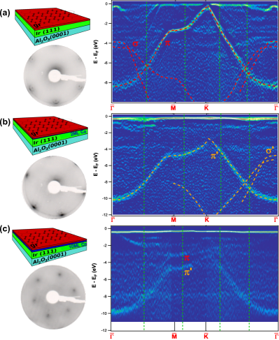
In order to understand the importance of the hybridization effects involving Gr -states for the enhancement of SOC at the interface, we first performed ARPES measurements of the electronic structure before and after Co intercalation. The procedure adopted for the preparation of epitaxial Gr-based heterostructures is described in more detail in the Methods section. A 30-nm-thick Ir buffer was DC sputtered at 670 K on an insulating Al2O3(0001) substrate, onto which epitaxial Gr was subsequently grown by ethylene dissociation at 1025 K. After Gr growth, Co was deposited by electron-beam evaporation at room temperature, while its intercalation under Gr was promoted by a moderate thermal annealing. The high quality of the interfaces and the completion of the intercalation process were checked by ARPES and low-energy electron diffraction (LEED), see Figs. 1 and 2. The Gr/Ir(111) structure was demonstrated to exhibit the well-known 1010 moiré pattern due to the coexistence of the incommensurate unit cells of Ir and Gr Blanco-Rey et al. (2021a); Ajejas et al. (2020); N’Diaye et al. (2008), as can be seen in Fig. 2(a).
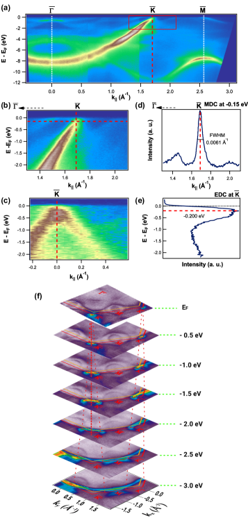
The energy-momentum band dispersion of Gr/Ir/Al2O3 (0001) measured by ARPES along the -- direction of the Gr SBZ is depicted in Figs. 1(a)-1(c). The overall electronic structure is consistent with the characteristic quasi-freestanding character of the Gr layer on Ir(111), and comparable to the case of Gr grown on Ir(111) single-crystal substrates Klimovskikh et al. (2015); Pletikosic et al. (2009); Kralj et al. (2011); Pletikosic et al. (2010), proving the high quality of the interface. The measured Gr and bands are very sharp and intense, as evidenced by the momentum-distribution curve (MDC) at an energy of E-E = -150 meV and the energy-distribution curve (EDC) at the point of the Gr SBZ (Figs. 1(d) and 1(e), respectively), confirming again the interface quality. The dominant feature in the spectrum is the Gr band. The bottom of the band at is located at an energy of E-E -8.28 eV and disperses linearly towards the E, resulting in the formation of a slightly -doped Dirac cone, as inferred from the MDC and EDC analyses. The narrowest MDC corresponding to an energy of -150 meV can be fitted to a Lorentzian function, whose full width at half maximum (FWHM) is 0.0061 Å-1, similar to the FWHM value obtained for Gr grown on Ir(111) single-crystal substrates Kralj et al. (2011). In the band dispersion the band replicas can be distinguished, which appear due to the additional periodicity of the moiré lattice despite their much lower intensity when compared to the main Gr Dirac cone at this photon energy (h = 64 eV).
The Dirac cones are also visible at the Fermi surface (FS) and constant energy (CE) maps shown in Fig. 1(f). Here, the main Dirac cones at and points, whose dispersion is indicated by red dashed lines, exhibit the characteristic trigonal symmetry of quasi-freestanding Gr on Ir(111), and coexist with the band dispersion of Ir 5 states typically observed in Ir(111) bulk single crystals Vita et al. (2014); Starodub et al. (2011). Note that these main Ir 5 ellipsoidal-shaped features close to the E are also visible in the curvature ARPES band maps of Fig. 2(a). The Gr and Ir SBZs, indicated by red and orange hexagons in Fig. 1(f), can be clearly identified from the intensity of the CE contours associated to the different features. Additionally, hybridization between Ir 5 and Gr states can be observed in the energy region between -1 and -4 eV, resulting into a reduction of the spectral weight at the band crossings as seen along the - direction. Nonetheless, the hybridization effects are sufficiently weak that the overall quasi-relativistic Dirac-like dispersion is largely preserved, as in the case of weakly bonded systems, where the electronic structure is usually similar or close to that of freestanding Gr.
In Fig. 2 and Fig. S1 in Supplementary Information (SI), we provide an overview of the electronic band structure as seen by ARPES along the --- direction before (Fig. 2(a)) and after intercalation of an epitaxial Co film of 2 and 10 monolayers (ML) thickness (Figs. 2(b) and 2(c), respectively). The LEED images in Figs. 2(a) and 2(b) display signatures of a moiré pattern and a clear commensurate Gr structure can be observed in the corresponding panel of Fig. 2(c), indicating in all cases a complete Co intercalation. In-line with previous discussion, the overall energy-momentum dispersion of Gr and states is close to that of a weakly interacting layer system (Fig. 2(a)). Similar to Fig. 1, here one can recognize between -4 eV and the E the dispersing Ir-derived bands which, as also observed in Figs. 3(a) and 4(a), consist mainly of the two concentrical ellipsoidal pockets centered at the point of Ir SBZ Vita et al. (2014); Starodub et al. (2011) and the Rashba-split Ir surface state (SS) dispersing towards Varykhalov et al. (2012).
Upon Co intercalation, the overall electronic band structure of Gr/Ir becomes highly modified because of the strong interaction with the Co layer. As a result, the Gr band for a 2-ML-thick intercalated Co film is already significantly shifted down in energy by 2 eV, as seen in Fig. 2(b) and Figs. S1 and S2 in SI. In particular, the bottom of the band at the point is shifted from -8.28 to -10.08 eV, and the Dirac cone merges with Co 3 states at an energy of -2.80 eV in the vicinity of the point. Despite the fact that the intensity and sharpness of the Gr bands are reduced when compared to the case of Gr/Ir in Fig. 2(a), the resulting changes in the overall band dispersion can still be clearly observed. Further Co intercalation results in a double-like band dispersion as seen in the ARPES maps of Fig. 2(c) and in the EDC profiles extracted at the momentum positions indicated by green dashed lines in Fig. 2 and reported in Fig. S2 (SI). The double band feature can be interpreted as a nearly-undisturbed Gr/Ir band closer to the E plus the more electronically doped Gr/Co at higher binding energies, associated with a highly-interacting, commensurate phase. As reported earlier Blanco-Rey et al. (2021a), the intercalation of further Co layers leads to a relaxation of the Co lattice resulting in a strong corrugation of the Gr layer. Although the intercalation of Co underneath Gr is layer-by-layer and epitaxial Blanco-Rey et al. (2021a), the formation of Co clusters or inhomogeneities at large thicknesses cannot be completely ruled out and can eventually lead to a more corrugated Gr layer Blanco-Rey et al. (2021a); Pacilé et al. (2014). The double-like band dispersion can thus be associated to a corrugated Gr layer where the band feature would appear due to weakly interacting, hill, C atoms, while the band would arise from highly interacting, valley, C atoms. As indicated by the EDC profiles shown in Fig. S2 (SI), this doubly-dispersing state is consistent with a simultaneous contribution from both highly interacting Gr-Co states and a less interacting Gr-Ir band (blue and red dashed lines in Fig. S2), respectively), in qualitative agreement with previous findings on other intercalated systems Pacilé et al. (2014).
Furthermore, in Figs. 2(b) and 2(c) several prominent Co electronic states can be identified: (i) a narrow and highly intense Co peak close to the E, present along the entire --- direction in an energy range between -0.2 and -0.5 eV, and common to the two selected Co thicknesses; (ii) for the thicker Co system (Fig. 2(c)), a highly localized and broad state located at an energy of -8.0 eV is present in the band structure, which could be indicative of a more disordered thicker, though epitaxial, Co layer; (iii) another Co-derived band strongly dispersing from -1.9 eV to the E towards , which confirms that, aside from the possible disorder, the intercalation of the thickest Co layer is mainly epitaxial; (iv) other localized states can be observed for the 10 ML Co system at -1.1 and -2.9 eV, while Ir features disappear as the Co thickness is increased.
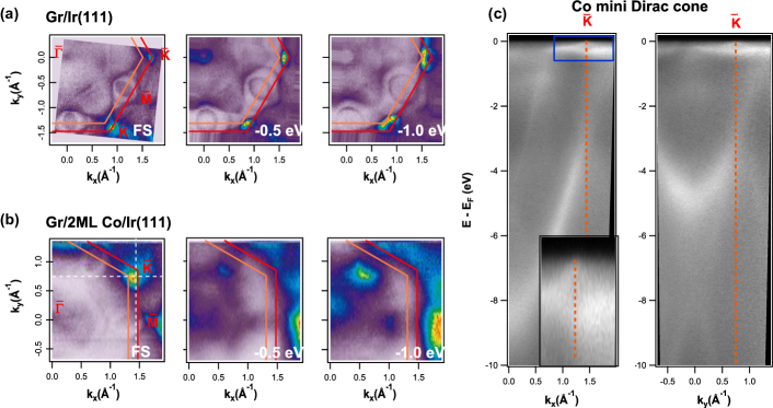
Let us now turn our attention to the electronic properties of the 2 ML Co system in more detail. Previous ARPES measurements have shown how after intercalation of one or more Co layers, the Ir bands close to the E can barely be distinguished, while the Co 3 states are so intense and broad that the Ir 5 bands become blurred and diffuse Pacilé et al. (2014); Vita et al. (2014). A zoom-in on the electronic structure from the E to -5.5 eV for both Gr/Ir and Gr /2 ML Co /Ir systems along the - and - directions is shown in Fig. 3 and Fig. S3 (SI), respectively. Raw and curvature ARPES band maps are displayed for both systems. Correspondingly, the FS and CE maps are also presented in Figs. 4(a) and 4(b), as well as Fig. S4 in SI.
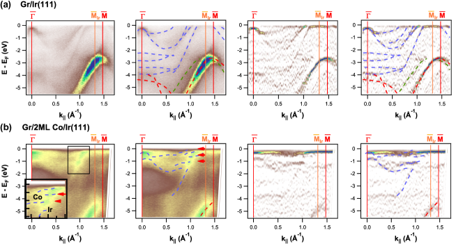
First, it should be noted that, contrary to previous studies, different bands corresponding to the electronic states of the underlying Ir(111) layer can always be detected. Noticeably, the electronic states that make up the ellipsoidal electron pockets centered at (Fig. 4(a)) are unambiguously resolved at the FS (Fig. 4(b)), namely the prominent Ir-derived band dispersing from -3.8 eV at 0.6 Å-1 to the E at 1.13 Å-1 along the - direction (Fig. 3(b)), which coincides with the same band for the Gr/Ir system (Fig. 3(a)). Particularly, hybridization between Co 3 states at -0.5 and -1.2 eV (clearly resolved between 0.5 and 0.8 Å-1 along the -) direction and the Ir dispersing band becomes evident, as reflected in the regions of increased intensity (red arrows on raw ARPES band maps in Fig. 3(b), left) and by the gap opening observed in both, raw and curvature, ARPES band maps (blue dashed lines in Fig. 3(b), right). The main gap opening of Ir dispersing band occurs between -1.1 and -0.65 eV at 0.99 Å-1 along the - direction(magnified in the inset of Fig. 3(b)).
This hybridization is also reflected in the CE maps at -0.5 and -1.0 eV in Figs. 4(a) and 4(b): the Ir ellipsoidal pockets near the E in Gr/Ir (Fig. 4(a)), become closed ellipses when interacting with these Co 3 states (Fig. 4(b)). Note also that, besides the Co-Ir hybridization close to , the Ir Rashba SS Varykhalov et al. (2012), with negative effective mass and maximum intensity at -0.26 eV at , is still preserved after Co intercalation (albeit slightly modified by the interaction with Co 3 states), as it can be inferred from the band maps along both - (Fig. 3) and - (Fig. S3 in SI) directions. Therefore, the Ir Rashba SS at and Ir 5 bands close to are preserved and hybridized after the intercalation of 2 ML Co. Another significant feature of the electronic structure of the 2 ML Co system is the development of mini Dirac cones in a narrow energy region of 0.2 eV below the E at the point (Fig. 4(c)). These mini Dirac cones have been previously observed in a perfectly oriented Gr layer on a Co(0001) surface and they strongly depend on the epitaxial quality of the interface Usachov et al. (2015). The mini Dirac cones are due to the interaction of C 2 and Co 3 orbitals, have a fully two-dimensional character with their wave functions located at the interface, and are spin polarized. The development of the mini Dirac cone in the measured band dispersions is another hallmark of both the Co-C interaction and our interface quality.
To summarize this part, after 2 ML of intercalated Co, the SS and Ir 5 bands are preserved at the E and become strongly modified just below it due to the interaction with Co 3 electronic states. Moreover, the perfectly oriented epitaxial layer leads to the formation of the mini Dirac cone as a result of the Co-C interaction. Further Co intercalation decouples Ir(111) electronic structure from the Gr/Co interface, resulting in the possibility of introducing some disorder effects. From our ARPES results we have provided direct spectroscopic evidence of the Co-Ir electronic hybridization, including the Ir(111) Rashba SS, as well as the Co-C electronic interaction. Thus, based on our findings, we can assign the Ir(111) layer interaction with the C atoms via the intercalated Co layer (at least for the lower Co thickness) as the main source of SOC at the Gr/Co interface. We note, however, that while this mechanism can result in high DMI values at Gr/Co interfaces, it also induces a strong SOC in the Gr layer which has previously been thought to be negligible and, therefore, not the reason for the observed enhancement of interfacial DMI Yang et al. (2018); Ajejas et al. (2018); Blanco-Rey et al. (2021b).
II.2 Large Rashba-type spin-orbit splitting of Gr -states at the Gr/Co interface
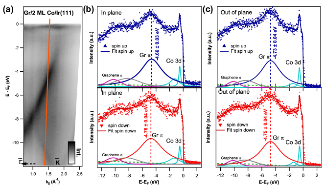
In order to investigate whether an extrinsic or intrinsic spin-orbit induced spin-splitting is generated in the Gr states by Co intercalation, we performed spin-resolved ARPES measurements and DFT calculations. To this end, spin-resolved ARPES spectra were acquired at selected wave vectors, , of the Gr SBZ (Figs. 5(a)). The spin-resolved EDCs for Gr /2 ML Co /Ir /Al2O3(0001) are presented in Figs. 5(b) and 5(c) (in-plane chiral and out-of-plane spin components, respectively), measured at 1.48 Å-1 along the - direction, as indicated by the dashed vertical line in the ARPES band map of Fig. 5(a), which crosses the region of the doped main Dirac cone with a stronger Gr character.
To isolate and extract the precise contribution from the Gr band in each spin channel separately, the spin-resolved EDCs in Fig. 5 have been normalized and fitted using five different components, which correspond to: the two peaks closer to the E arising from Co 3 states (turquoise in Figs. 5(b) and 5(c); the Gr band contribution (purple); the wider feature appearing after Co intercalation (grey, almost negligible contribution from disordered or localized states); and the intense contribution from Gr states (blue for spin up, and red for spin down). This analysis has been applied consistently to both spin up and spin down spectra (blue and red colors respectively), which were simultaneously acquired using independent electron counters.
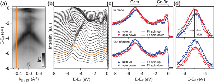
As clearly seen in Fig. 5(b), there is a large energy spin-splitting in the in-plane chiral spin component for Gr states of E = (100 40) meV. Conversely, the out-of-plane spin up and down spectra in Fig. 5(c) do not show any sizeable spin-splitting above the average error of the curve fitting procedure, E = (20 40) meV. The energy spin-splitting seen in the in-plane chiral spin component for the Gr band is consistent with the one reported for Au and Pb intercalated layers at similar values along the - direction Marchenko et al. (2012); Otrokov et al. (2018). In Fig. 6, we further corroborate this result for 4 ML Co intercalated Gr on Ir(111) along the momentum direction of the Gr SBZ orthogonal to the - direction. Note that similar to Fig. 5, the in-plane chiral spin up and spin down orientations in Fig. 6, which are perpendicular to the electron momentum, are also tangential to the Dirac cone, however rotated by 90 degrees with respect to Fig. 5.
In Figs. 6(a) and 6(b), a spin-integrated band dispersion of the Dirac cone alongside spin-integrated EDCs are shown, taken with 45 eV photons and along the direction perpendicular to - for a Gr/4 ML Co grown on Ir(111) single-crystal. Figure 6(c) shows spin-resolved EDCs corresponding to the in-plane chiral and out-of-plane spin components, measured at the momentum position indicated by both the vertical solid line in Fig. 6(a) and the spin-integrated EDC highlighted in Fig. 6(b). As it can be also seen in a zoom-in over the range of the Gr band in Fig. 6(d), a large energy spin-splitting consistent with the spin-resolved measurements of Fig. 5 is clearly resolved in the in-plane chiral spin component for Gr states. Taking altogether, the chiral spin up and spin down orientations in Fig. 5(b) and 6(d) are consistent with a spin-orbit splitting predominantly associated with an in-plane Rashba-type spin texture that is characterized by a counterclockwise (clockwise) spin circulation around for the outer (inner) band spin states. This observation rules out the possibility of a collinear alignment of antiparallel spin vectors in a global spin texture whose origin would be entirely magnetic. In this respect, it should be noted that due to the energy dependent hybridization, spin-orbit effects with reducing energy are increasingly more difficult to resolve, as the lower half of the Dirac cone possesses very strong Co character, resulting in an overall spin texture that is more complex. This effect is manifested by an out-of-plane canting of electron spins which can be nevertheless observed in Fig. 6(d), despite the reduced Co weight in this energy region. The energy spin-splitting is consistent with the previous estimation from Fig. 5.
Keeping this in mind, as next step, spin-resolved ARPES measurements were also performed on the thicker, 10 ML Co system (see Fig. S5 in SI). Despite the increasing spectral broadening of Gr states induced by Co intercalation, we do not resolve any spin-orbit splitting of considerable size between opposite spin states. This is consistent with our analysis of the Gr band contribution in each spin channel, indicating that any possible energy spin-splitting is well below the fitting errors for both in-plane chiral and out-of-plane spin components. Such absence of measurable spin-orbit splitting for Gr states in thicker intercalated Co films is in agreement with previous findings for Gr grown on Co bulk single-crystal substrates Rader et al. (2009). These observations support our ARPES findings that at larger Co thickness the Gr/Co interface is electronically decoupled from the Ir underlayer, and emphasizes the critical role of the tunable interaction between Gr and the HM layer via the FM as source of SOC for C atoms. Accordingly, a large Rashba-SOC at the Gr/Co interface originating from the Gr layer, which in contrast to our findings was previously thought to be negligible and thus not important for the observed enhancement of interfacial DMI, is consistent with the energy spin-splitting we observe in the in-plane chiral spin component for Gr the states in the thinner intercalated Co films.
II.3 DFT calculations of Co-intercalated Gr/Ir interface
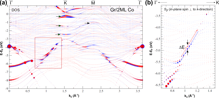
In an attempt to further verify our experimental findings, we performed DFT calculations for 2 ML of epitaxial Co intercalated in a Gr 11 /Ir(111) interface, with spin-orbit interaction fully taken into account. To reduce the complexity of the problem, in the calculations Gr 11 was expanded to match with the Ir lattice, and thus and high-symmetry points are referred to the Ir(111) SBZ. In this way, contributions from Gr moiré superlattice to the electronic structure are explicitly neglected. In Fig. 7(a) we display the surface-projected band structure for Gr /2 ML Co /Ir(111) as determined by DFT (see Methods) along the --- direction. Here, we highlight the contribution of the density of states (DOS) of Gr and Ir at the Gr/Co interface, while the color representation indicates the opposite orientations of the in-plane chiral spin component at the interface, which are perpendicular to electron momentum. Overall, the calculation shows qualitatively good agreement with the experimental results. The area of the circles is proportional to DOS (Gr) DOS (Ir), being thus indicative of the hybridization between Gr and Ir. More details on the spin- and surface-projected band structures are provided in SI, Fig. S6.
By directly comparing the DFT calculations with the experiment, it can be clearly seen that the Gr bands are preserved and hybridized with Ir-Co states at the interface, resulting in a significant Gr-Ir interaction (energy-momentum region indicated by a rectangle in Fig. 7(a)). The main Dirac crossing point of the Gr band at the point is located at an energy of E-E = -3 eV, in good agreement with the experimental results (see Fig. 2(b) and supplementary Figs. S1-S4). Similarly, in Fig. 7(a), clear signatures of the Gr-Ir hybridization can be also identified at -1.5 eV and in the vicinity of the E around (green arrows), where the strong C-Co hybridization gives rise to the characteristic mini Dirac cone as experimentally observed (Fig. 4(c)). Note that the calculations neglect the band shift due to electron doping, therefore the mini Dirac cone appears slightly above the E. Moreover, near the point there is a small enhancement of the DOS (black arrow in Fig. 7(a)) consistent with the Ir-Co hybridization that is observed in the ARPES measurements (Figs. 3, 4 and Fig. S3 in SI).
In Fig. 7(b), we provide a closer view of the energy-momentum dispersion of Gr states along the - direction. Here, we show the calculated in-plane chiral spin component in the Gr layer within the energy and momentum ranges corresponding to the region indicated by a rectangle in Fig. 7(a). Noticeably, the chiral spin up and spin down orientations in Fig. 7(b) correspond those in Fig. 7(a). In both cases, there is a large energy spin-splitting in the in-plane chiral spin component between Gr band states of opposite spin, confirming the crucial role of the spin-orbit interaction induced in the Gr layer for the enhancement of SOC at the interface. The spin-splitting is significantly pronounced in an energy region between E-E = -6 eV and -4 eV, that is, as the momentum approaches the point, in very good agreement with our spin-resolved ARPES measurements (see Figs. 5 and 6). This spin-orbit splitting, which exceeds by far the one originating from SOC variations in the Co layer and is highlighted by red and blue solid lines in Fig. 7(b), is in quantitative agreement with the energy spin-splitting experimentally observed, that is, we recall, 100 meV. Consistent with this, a careful examination of the Gr states in this energy region clearly shows that they are hybridized with the states localized at Ir (and Co) at the interface (larger DOS inside the rectangle in Fig. 7(a)). Thus, our theoretical calculations largely agree with the experimental results and demonstrate the strong electronic interaction between electronic states of Gr and those of the Ir-Co interface as well as a pronounced in-plane energy spin-splitting. In other words, the obtained results confirm the Rashba-like spin-texture induced by Ir in the Gr layer and shed light on the microscopic mechanism that is ultimately responsible for a significant enhancement of SOC at the Gr/Co interface in the experimental picture.
III CONCLUSION
To summarize, through angle-resolved photoemission spectroscopy with and without spin resolution in combination with DFT calculations we have investigated the electronic origin of the large DMI at Gr/FM interfaces. To this end, we have performed a systematic experimental characterization of the electronic properties of high-quality Gr-based heterostructures containing atomically flat interfaces, as well as homogeneous epitaxial Co layers intercalated between Gr and a Ir(111) buffer layer grown on insulating substrates. Our findings reveal that, in contrast to conventional wisdom, spin-orbit effects induced in the Gr layer are of central importance to fundamentally understand the enhancement of SOC at Gr/FM interfaces. The effect is manifested by a large energy spin-splitting in the in-plane chiral component of spin for Gr states, consistent with a Rashba spin texture and a spin-orbit splitting that exceeds by far the one originating from SOC variations in the Co layer. The experimental results are supported by DFT calculations pinpointing the tunable interaction between Gr and the Ir underlayer as the main source of SOC for C atoms. These findings are consistent with a large Rashba-SOC at the Gr/Co interface arising from the Gr layer in ultrathin intercalated Co films, and provide a convenient way to explore routes towards achieving unprecedented control of the interfacial properties. Our present findings taken altogether are highly relevant for the development of Gr-based memory and logic devices with advanced functionalities for future spintronic applications.
IV METHODS
Sample growth and characterization. The samples were grown at the Molecular Beam Epitaxy (MBE) chamber at IMDEA Nanoscience (Madrid, Spain), and transferred to the Cassiopée beamline end station at SOLEIL synchrotron (Gif-sur-Yvette, France) using an ultrahigh vacuum (UHV) suitcase at pressures below 5 10-10 mbar. Gr-based epitaxial heterostructures were grown under UHV conditions on commercially available Al2O3(0001)-oriented oxide single crystals. The insulating substrates were ex-situ annealed in air at 1370 K for 2 hours in order to obtain flat surfaces with large terraces prior to their insertion into the MBE chamber. Epitaxial (111)-oriented 30 nm thick Ir buffers were deposited by DC sputtering at 670 K in 8 10-3 mbar Ar partial pressure with a deposition rate of 0.3 Å/s. The epitaxial quality of the fabricated Ir layers was verified by LEED and XPS. Epitaxial Gr was subsequently grown at 1025 K by exposing the samples to ethylene gas at a partial pressure of 2 10-8 mbar for 30 min. After cooling down to room temperature, Co was deposited by electron-beam evaporation on top of Gr/Ir/Al2O3(0001) with a deposition rate of 0.04 Å/s, while its intercalation under Gr was promoted by a moderate thermal annealing. During this process, the sample was gradually heated up to 550 K while acquiring XPS spectra to verify in real time the complete intercalation of Co underneath the Gr layer. The XPS spectrum of Co was not modified by the presence of Co-C Ajejas et al. (2020) which rules out diffusion of C. The 4 ML Co-intercalated sample for spin-resolved ARPES measurements was grown in-situ at the spin-ARPES end station permanently installed at the U125-PGM beamline of BESSY-II. The Co source was carefully calibrated using a quartz crystal monitor.
Photoemission experiments. ARPES measurements were carried out at room temperature at the Cassiopée beamline HR-ARPES end station, and at the spin-ARPES station at the U125-PGM beamline of BESSY-II in Helmholtz-Zentrum Berlin. Photoemission spectra were acquired using linearly-polarized synchrotron light at photon energies of h = 64 eV and 45 eV, respectively. The base pressure of the photoemission setups was better than 1 10-10 mbar. Emitted photoelectrons were detected with Scienta R4000 hemispherical analyzers up to acceptance angles of 15∘. The angular and energy resolutions were set to 0.1∘ and 5 meV, respectively.
Spin-resolved measurements. Spin-resolved ARPES data in Fig. 5 were acquired at a photon energy of 64 eV at the spin-ARPES end-station of Cassiopée beamline at SOLEIL synchrotron, using a SES2002 Scienta analyzer coupled to a Mini-Mott spin detector capable of detecting simultaneously both in-plane chiral (perpendicular to analyzer slit) and out-of-plane spin components (perpendicular to the surface plane). The energy resolution of the spin-resolved measurements was 230 meV, and the angular resolution was 3.6∘. A home-made Igor Wavemetrics Fitting procedure program was used to fit spectra in Fig. 5. This procedure considers the Fermi level step and cutoff and its intrinsic broadening due to resolution and temperature, a Shirley background function and a multi-peak Voigt function to fit the several photoemision features. For each peak, the fitting parameters are related to their amplitude, width, energy and shape. The peak line-shape parameter can be modeled as a Voigt function to take into account the Gaussian broadening intrinsic to the experimental resolution. Spin-resolved data in Fig. 6 were acquired at the U125-PGM beamline of the BESSY-II synchrotron light source, using a Scienta R4000 analyzer coupled to a Rice
University Mott-type spin polarimeter operated at 25 kV. Resolutions of the spin-resolved ARPES measurements were 45 meV (energy) and 0.75∘ (angular). The spin-resolved EDCs were fitted using Lorentzian peaks and a Shirley background, multiplied with a Fermi-function, and convoluted with a Gaussian broadening to account for the finite experimental resolution.
Theoretical calculations. We used DFT in the generalized gradient approximation Perdew et al. (1996) employing the full-potential linearized augmented-plane-wave method as implemented in the Fleur code Kurz et al. (2004). Relativistic effects, including spin-orbit coupling, were fully included. To calculate the electronic structure of Gr 11 /2 ML Co /Ir(111), a seven layer Ir(111) film was used as substrate, and different stackings were considered as a starting point for the structures to relax. The lowest energy was obtained when one C atom was situated above the top Co and the other in a fcc position. To obtain the surface- and spin-projected band structures, spin-orbit coupling with an out-of-plane spin-quantization axis was considered, enabling non-collinear calculations to resolve the in-plane spin components in the different layers.
V ACKNOWLEDGMENTS
This project has received funding from the FLAG-ERA JTC 2019 grant SOgraphMEM through the partner’s national research agencies (Spain, AEI PCI2019-111867-2, France, ANR-19-GRF1-0001-07, Germany DFG-SOgraphMEM). IMDEA team acknowledges support by the Community of Madrid (CM) through Project P2018/NMT-4321 (NANOMAGCOST), by MICIN/AEI through Projects RTI2018-097895-B-C42 (FUN-SOC), PGC2018-098613-B-C21 (SpOrQuMat), PID2021-122980OB-C52 (ECLIPSE-ECoSOx), EQC2019-006304-P, PID2020-116181RB-C31 (SOnanoBRAIN) and PID2021-123776NB-C21 (CONPHASETM), and by the ’Severo Ochoa’ Programme for Centres of Excellence in R&D, MINECO grant CEX2020-001039-S. B.M.C., A.G. and I.A. acknowledge support from CM (PEJD-2019-PRE/IND-17048, PEJD-2017-PRE/IND-4690 and PEJD-2019-POST/IND-15343, respectively) and J.M.D. from MINECO (BES 2017-080617). We acknowledge SOLEIL for provision of synchrotron radiation facilities and we would like to thank CASSIOPÉE beamline staff for assistance (experiment no. 20181593) and SEXTANTS beamline staff (in-house experiments). J.S.-B. acknowledges financial support from the Impuls- und Vernetzungsfonds der Helmholtz-Gemeinschaft under grant No. HRSF-0067. P.P. acknowledges fruitful discussions with Dr. Nicolas Jaouen, Dr. Jorge I. Cerdá (in memoriam) and Prof. Andrés Arnau.
References
- Spi (2015) Spintronics for Next Generation (Wiley Series in Materials for Electronic & Optoelectronic Applications, 2015).
- Castro Neto et al. (2009) A. H. Castro Neto, F. Guinea, N. M. R. Peres, K. S. Novoselov, and A. K. Geim, Rev. Mod. Phys. 81, 109 (2009).
- Han et al. (2014) W. Han, R. K. Kawakami, M. Gmitra, and J. Fabian, Nat. Nanotechnol. 9, 794 (2014).
- Avsar et al. (2019) A. Avsar, H. Ochoa, F. Guinea, B. Ozyilmaz, B. J. van Wees, and I. J. Vera-Marun, Rev. Mod. Phys. 92, 21003 (2019).
- Drögeler et al. (2016) M. Drögeler, C. Franzen, F. Volmer, T. Pohlmann, L. Banszerus, M. Wolter, K. Watanabe, T. Taniguchi, C. Stampfer, and B. Beschoten, Nano Lett. 16, 3533 (2016).
- Guimarães et al. (2014) M. H. Guimarães, P. J. Zomer, J. Ingla-Aynés, J. C. Brant, N. Tombros, and B. J. Van Wees, Phys. Rev. Lett. 113, 086602 (2014).
- Ingla-Aynés et al. (2015) J. Ingla-Aynés, M. H. D. Guimarães, R. J. Meijerink, P. J. Zomer, and B. J. van Wees, Phys. Rev. B 92, 201410 (2015).
- Yan et al. (2017) W. Yan, E. Sagasta, M. Ribeiro, Y. Niimi, L. E. Hueso, and F. Casanova, Nat. Commun. 8, 661 (2017).
- Savero Torres et al. (2017) W. Savero Torres, J. F. Sierra, L. A. Benitez, F. Bonell, M. V. Costache, and S. O. Valenzuela, 2D Mater. 4, 041008 (2017).
- Soumyanarayanan et al. (2016) A. Soumyanarayanan, N. Reyren, A. Fert, and C. Panagopoulos, Nature 539, 509 (2016).
- Kane and Mele (2005) C. L. Kane and E. J. Mele, Phys. Rev. Lett. 95, 226801 (2005).
- Tse et al. (2011) W. K. Tse, Z. Qiao, Y. Yao, A. H. MacDonald, and Q. Niu, Phys. Rev. B 83, 155447x (2011).
- Bernevig et al. (2006) B. A. Bernevig, T. L. Hughes, and S.-C. Zhang, Science 314, 1757 (2006).
- Chang et al. (2013) C.-Z. Chang, J. Zhang, X. Feng, J. Shen, Z. Zhang, M. Guo, K. Li, Y. Ou, P. Wei, L.-L. Wang, Z.-Q. Ji, Y. Feng, S. Ji, X. Chen, J. Jia, X. Dai, Z. Fang, S.-C. Zhang, K. He, Y. Wang, L. Lu, X.-C. Ma, and Q.-K. Xue, Science 340, 167 (2013).
- Weeks et al. (2011) C. Weeks, J. Hu, J. Alicea, M. Franz, and R. Wu, Phys. Rev. X 1, 021001 (2011).
- Zhang et al. (2012) H. Zhang, C. Lazo, S. Blügel, S. Heinze, and Y. Mokrousov, Phys. Rev. Lett. 108, 056802 (2012).
- Fert et al. (2013) A. Fert, V. Cros, and J. Sampaio, Nat. Nanotechnol. 8, 152 (2013).
- Yu et al. (2010) X. Z. Yu, Y. Onose, N. Kanazawa, J. H. Park, J. H. Han, Y. Matsui, N. Nagaosa, and Y. Tokura, Nature 465, 901 (2010).
- Cai et al. (2017) K. Cai, M. Yang, H. Ju, S. Wang, Y. Ji, B. Li, K. W. Edmonds, Y. Sheng, B. Zhang, N. Zhang, S. Liu, H. Zheng, and K. Wang, Nature Materials 16, 712 (2017).
- Yu et al. (2014) G. Yu, P. Upadhyaya, Y. Fan, J. G. Alzate, W. Jiang, K. L. Wong, S. Takei, S. A. Bender, L. T. Chang, Y. Jiang, M. Lang, J. Tang, Y. Wang, Y. Tserkovnyak, P. K. Amiri, and K. L. Wang, Nature Nanotechnology 9, 548 (2014).
- Cao et al. (2020) Y. Cao, Y. Sheng, K. W. Edmonds, Y. Ji, H. Zheng, and K. Wang, Advanced Materials 32, 1907929 (2020).
- Cao et al. (2022) Y. Cao, X. Zhang, X. P. Zhang, F. Yan, Z. Wang, W. Zhu, H. Tan, V. N. Golovach, H. Zheng, and K. Wang, Physical Review Applied 17, L051001 (2022).
- Gmitra et al. (2009) M. Gmitra, S. Konschuh, C. Ertler, C. Ambrosch-Draxl, and J. Fabian, Phys. Rev. B 80, 235431 (2009).
- Marchenko et al. (2013) D. Marchenko, J. Sánchez-Barriga, M. R. Scholz, O. Rader, and A. Varykhalov, Phys. Rev. B 87, 115426 (2013).
- Avsar et al. (2014) A. Avsar, J. Y. Tan, T. Taychatanapat, J. Balakrishnan, G. K. Koon, Y. Yeo, J. Lahiri, A. Carvalho, A. S. Rodin, E. C. O’Farrell, G. Eda, A. H. Castro Neto, and B. Özyilmaz, Nat. Commun. 5, 4875 (2014).
- Balakrishnan et al. (2014) J. Balakrishnan, G. K. W. Koon, A. Avsar, Y. Ho, J. H. Lee, M. Jaiswal, S. J. Baeck, J. H. Ahn, A. Ferreira, M. A. Cazalilla, A. H. Neto, and B. Özyilmaz, Nat. Commun. 5, 4748 (2014).
- Dedkov et al. (2008) Y. S. Dedkov, M. Fonin, U. Rüdiger, and C. Laubschat, Phys. Rev. Lett. 100, 107602 (2008).
- Marchenko et al. (2012) D. Marchenko, A. Varykhalov, M. R. Scholz, G. Bihlmayer, E. I. Rashba, A. Rybkin, A. M. Shikin, and O. Rader, Nat. Commun. 3, 1232 (2012).
- Otrokov et al. (2018) M. M. Otrokov, I. I. Klimovskikh, F. Calleja, A. M. Shikin, O. Vilkov, A. G. Rybkin, D. Estyunin, S. Muff, J. H. Dil, A. L. Vázquez De Parga, R. Miranda, H. Ochoa, F. Guinea, J. I. Cerdá, E. V. Chulkov, and A. Arnau, 2D Mater. 5, 035029 (2018).
- Calleja et al. (2015) F. Calleja, H. Ochoa, M. Garnica, S. Barja, J. J. Navarro, A. Black, M. M. Otrokov, E. V. Chulkov, A. Arnau, A. L. Vázquez De Parga, F. Guinea, and R. Miranda, Nat. Phys. 11, 43 (2015).
- Varykhalov et al. (2015) A. Varykhalov, J. Sánchez-Barriga, D. Marchenko, P. Hlawenka, P. S. Mandal, and O. Rader, Nat. Commun. 6, 7610 (2015).
- Klimovskikh et al. (2015) I. I. Klimovskikh, O. Vilkov, D. Y. Usachov, A. G. Rybkin, S. S. Tsirkin, M. V. Filianina, K. Bokai, E. V. Chulkov, and A. M. Shikin, Phys. Rev. B 92, 165402 (2015).
- Klimovskikh et al. (2017) I. I. Klimovskikh, M. M. Otrokov, V. Y. Voroshnin, D. Sostina, L. Petaccia, G. Di Santo, S. Thakur, E. V. Chulkov, and A. M. Shikin, ACS Nano 11, 368 (2017).
- Karpan et al. (2007) V. M. Karpan, G. Giovannetti, P. A. Khomyakov, M. Talanana, A. A. Starikov, M. Zwierzycki, J. V. D. Brink, G. Brocks, and P. J. Kelly, Phys. Rev. Lett. 99, 176602 (2007).
- Anadón et al. (2021) A. Anadón, A. Gudín, R. Guerrero, I. Arnay, A. Guedeja-Marron, P. Jiménez-Cavero, J. M. Díez Toledano, F. Ajejas, M. Varela, S. Petit-Watelot, I. Lucas, L. Morellón, P. A. Algarabel, M. R. Ibarra, R. Miranda, J. Camarero, J. C. Rojas-Sánchez, and P. Perna, APL Materials 9, 061113 (2021).
- Piquemal-Banci et al. (2020) M. Piquemal-Banci, R. Galceran, S. M. Dubois, V. Zatko, M. Galbiati, F. Godel, M. B. Martin, R. S. Weatherup, F. Petroff, A. Fert, J. C. Charlier, J. Robertson, S. Hofmann, B. Dlubak, and P. Seneor, Nat. Commun. 11, 5670 (2020).
- Gargiani et al. (2017) P. Gargiani, R. Cuadrado, H. B. Vasili, M. Pruneda, and M. Valvidares, Nat. Commun. 8, 699 (2017).
- Cobas et al. (2012) E. Cobas, A. L. Friedman, O. M. J. V. Erve, J. T. Robinson, and B. T. Jonker, Nano Lett. 12, 3000 (2012).
- Rader et al. (2009) O. Rader, A. Varykhalov, J. Sánchez-Barriga, D. Marchenko, A. Rybkin, and A. M. Shikin, Phys. Rev. Lett. 102, 057602 (2009).
- Varykhalov et al. (2008) A. Varykhalov, J. Sánchez-Barriga, A. M. Shikin, C. Biswas, E. Vescovo, A. Rybkin, D. Marchenko, and O. Rader, Phys. Rev. Lett. 101, 157601 (2008).
- Rougemaille et al. (2012) N. Rougemaille, A. T. Ndiaye, J. Coraux, C. Vo-Van, O. Fruchart, and A. K. Schmid, Appl. Phys. Lett. 101, 142403 (2012).
- Blanco-Rey et al. (2021a) M. Blanco-Rey, P. Perna, A. Gudin, J. M. Diez, A. Anadón, P. Olleros-Rodríguez, L. de Melo Costa, M. Valvidares, P. Gargiani, A. Guedeja-Marron, M. Cabero, M. Varela, C. García-Fernández, M. M. Otrokov, J. Camarero, R. Miranda, A. Arnau, and J. I. Cerdá, ACS Appl. Nano Mater. 4, 4398 (2021a).
- Yang et al. (2016) H. Yang, A. D. Vu, A. Hallal, N. Rougemaille, and J. Coraux, Nano Lett. 16, 145 (2016).
- Yang et al. (2018) H. Yang, G. Chen, A. A. C. Cotta, A. T. N. Diaye, S. A. Nikolaev, E. A. Soares, W. A. A. Macedo, K. Liu, A. K. Schmid, A. Fert, and M. Chshiev, Nat. Mater. 17, 605 (2018).
- Ajejas et al. (2018) F. Ajejas, A. Gud, R. Guerrero, A. Anadón, J. M. Diez, L. D. M. Costa, P. Olleros, M. A. Niño, S. Pizzini, J. Vogel, M. Valvidares, P. Gargiani, M. Cabero, M. Varela, J. Camarero, R. Miranda, and P. Perna, Nano Lett. 18, 5364 (2018).
- Vo-Van et al. (2010) C. Vo-Van, Z. Kassir-Bodon, Y. Hongxin, J. Coraux, J. Vogel, S. Pizzini, P. Bayle-Guillemaud, M. Chrhiev, L. Ranno, V. Guisset, P. David, V. Salvador, and O. Fruchart, New J. Phys. 12, 103040 (2010).
- Olleros-Rodríguez et al. (2020) P. Olleros-Rodríguez, R. Guerrero, J. Camarero, O. Chubykalo-Fesenko, and P. Perna, ACS Appl. Mater. Interfaces 12, 25419 (2020).
- Wang et al. (2020) Y. Wang, L. Wang, J. Xia, Z. Lai, G. Tian, X. Zhang, Z. Hou, X. Gao, W. Mi, C. Feng, M. Zeng, G. Zhou, G. Yu, G. Wu, Y. Zhou, W. Wang, X. xiang Zhang, and J. Liu, Nat. Commun. 4, 3577 (2020).
- Usachov et al. (2015) D. Usachov, A. Fedorov, M. M. Otrokov, A. Chikina, O. Vilkov, A. Petukhov, A. G. Rybkin, Y. M. Koroteev, E. V. Chulkov, V. K. Adamchuk, A. Gru, C. Laubschat, and D. V. Vyalikh, Nano Lett. 15, 2396 (2015).
- Pacilé et al. (2014) D. Pacilé, S. Lisi, I. Di Bernardo, M. Papagno, L. Ferrari, M. Pisarra, M. Caputo, S. K. Mahatha, P. M. Sheverdyaeva, P. Moras, P. Lacovig, S. Lizzit, A. Baraldi, M. G. Betti, and C. Carbone, Phys. Rev. B 90, 195446 (2014).
- Vita et al. (2014) H. Vita, S. Böttcher, P. Leicht, K. Horn, A. B. Shick, and F. Máca, Phys. Rev. B 90, 165432 (2014).
- Jugovac et al. (2020) M. Jugovac, F. Genuzio, T. O. Mentes, A. Locatelli, G. Zamborlini, V. Feyer, and C. M. Schneider, Carbon 163, 341 (2020).
- Fert and Levy (1980) A. Fert and P. M. Levy, Phys. Rev. Lett. 44, 1538 (1980).
- Fert (1991) A. Fert, In Metallic Multilayers, volume 59 of Materials Science Forum, 439-480. Trans Tech Publications Ltd (1991).
- Blanco-Rey et al. (2021b) M. Blanco-Rey, G. Bihlmayer, A. Arnau, and J. I. Cerda, arXiv 2111, 08556v1 (2021b), arXiv:2111.08556 .
- Ajejas et al. (2020) F. Ajejas, A. Anadon, A. Gudin, J. M. Diez, C. G. Ayani, P. Olleros-Rodríguez, L. De Melo Costa, C. Navío, A. Gutierrez, F. Calleja, A. L. Vázquez De Parga, R. Miranda, J. Camarero, and P. Perna, ACS Appl. Mater. Interfaces 12, 4088 (2020).
- N’Diaye et al. (2008) A. T. N. N’Diaye, J. Coraux, T. N. Plasa, C. Busse, and T. Michely, New J. Phys. 10, 043033 (2008).
- Pletikosic et al. (2009) I. Pletikosic, M. Kralj, P. Pervan, R. Brako, J. Coraux, A. T. N. Diaye, C. Busse, and T. Michely, Phys. Rev. Lett. 102, 056808 (2009).
- Kralj et al. (2011) M. Kralj, I. Pletikosić, M. Petrović, P. Pervan, M. Milun, A. T. N. Diaye, C. Busse, T. Michely, J. Fujii, and I. Vobornik, Phys. Rev. B 84, 075427 (2011).
- Pletikosic et al. (2010) I. Pletikosic, M. Kralj, D. Sokcevic, R. Brako, P. Lazic, and P. Pervan, J. Phys.: Condens. Matter 22, 135006 (2010).
- Starodub et al. (2011) E. Starodub, A. Bostwick, L. Moreschini, S. Nie, F. E. Gabaly, K. F. McCarty, and E. Rotenberg, Phys. Rev. B 83, 125428 (2011).
- Varykhalov et al. (2012) A. Varykhalov, D. Marchenko, M. R. Scholz, E. D. Rienks, T. K. Kim, G. Bihlmayer, J. Sánchez-Barriga, and O. Rader, Phys. Rev. Lett. 108, 066804 (2012).
- Zhang et al. (2011) P. Zhang, P. Richard, T. Qian, Y. Xu, X. Dai, and H. Ding, Rev. Sci. Instrum. 82, 043712 (2011).
- Ajejas et al. (2021) F. Ajejas, Y. Sassi, W. Legrand, S. Collin, A. Thiaville, J. P. Garcia, S. Pizzini, N. Reyren, V. Cros, and A. Fert, arXiv 2109, 00761 (2021), arXiv:2109.00761 .
- Perdew et al. (1996) J. P. Perdew, K. Burke, and M. Ernzerhof, Phys. Rev. Lett. 77, 3865 (1996).
- Kurz et al. (2004) P. Kurz, F. Förster, L. Nordström, G. Bihlmayer, and S. Blügel, Phys. Rev. B 69, 024415 (2004).