Massive MIMO Hybrid Precoding for LEO Satellite Communications With Twin-Resolution Phase Shifters and Nonlinear Power Amplifiers
Abstract
The massive multiple-input multiple-output (MIMO) transmission technology has recently attracted much attention in the non-geostationary, e.g., low earth orbit (LEO) satellite communication (SATCOM) systems since it can significantly improve the energy efficiency (EE) and spectral efficiency. In this work, we develop a hybrid analog/digital precoding technique in the massive MIMO LEO SATCOM downlink, which reduces the onboard hardware complexity and power consumption. In the proposed scheme, the analog precoder is implemented via a more practical twin-resolution phase shifting (TRPS) network to make a meticulous tradeoff between the power consumption and array gain. In addition, we consider and study the impact of the distortion effect of the nonlinear power amplifiers (NPAs) in the system design. By jointly considering all the above factors, we propose an efficient algorithmic approach for the TRPS-based hybrid precoding problem with NPAs. Numerical results show the EE gains considering the nonlinear distortion and the performance superiority of the proposed TRPS-based hybrid precoding scheme over the baselines.
Index Terms:
Non-geostationary satellite, LEO satellite, massive MIMO, hybrid precoding, twin-resolution phase shifting network, nonlinear power amplifier, statistical CSI, energy efficiency.I Introduction
Satellite communication (SATCOM) systems have an advantage in serving remote areas where terrestrial infrastructures are lacking [wang2019near] and will help to fill the gap for future global wireless communications, which aim at higher energy efficiency and throughputs. Recently, non-geostationary SATCOM systems, e.g., low earth orbit (LEO) SATCOM systems, which provide higher speed and lower latency services than the conventional geostationary counterparts, have received increased attention [al2021broadband, liu2021leo]. LEO SATCOM systems, which are deployed at altitudes from 500 to 2000 km, are of high interest due to the lower delay and less link loss in contrast to medium earth orbit (MEO) and high elliptical orbit (HEO) ones [you2020massive].
So far, some valuable techniques have been adopted in the SATCOM system to increase data rates, such as multibeam and massive multiple-input multiple-output (MIMO) transmission. In particular, the multibeam transmission technology provides a wider coverage for the user terminals (UTs) [gao2020robust, wang2021resource]. Among adjacent beams, an aggressive full frequency reuse scheme is adopted to increase the bandwidth efficiency, which unfortunately leads to inter-beam interference [wang2018robust, you2018outage]. Thus, linear precoding is adopted at the transmitter to mitigate the interference. In addition, the massive MIMO transmission technology offers a significant growth in available degrees of freedom and is promising for the LEO SATCOM systems to achieve better spectral efficiency (SE) and energy efficiency (EE). The combination of the multibeam and massive MIMO transmission technologies enables the implementation of dynamic multiple beamforming, which can be flexibly adjusted with the varying of the channels [li2020downlink].
Downlink LEO SATCOM systems feature several characteristics to be considered in the precoding design. In general, satellites usually utilize solar panels to provide power, supplemented by internal batteries when the sun is blocked by the earth, leading to non-negligible energy consumption. On the other hand, the payload capabilities in terms of energy consumption are restricted to the confined space of the satellites [fraire2020battery]. Yet, the existing works on the performance of the LEO SATCOM systems mainly focus on the rate performance metric [li2020downlink, arora19hybrid] and ignore the negative influence of the high power consumption at the transmitter on the whole system. Therefore, it is valuable to design a EE maximization-based precoder to achieve a tradeoff between the rate performance and the power consumption. Since EE is defined as the ratio of the sum rate and the power consumption, fractional programming is generally involved in the optimization of EE [rodenas1999extensions, zapponealessio2015energy].
An essential factor impacting the performance of the precoder at the LEO satellite transmitter is the accuracy of the obtained channel state information (CSI). In the LEO SATCOM systems, the propagation latency between the satellite and the UT is much longer than that in the terrestrial systems [wang2021location]. Also, the mobility of both the satellite and the UTs during data transmission results in severe Doppler effect.111For a Ku-band 11.45 GHz SATCOM system with satellite deployed at 1000 km, the doppler frequency and the round-trip delay are approximately 229 kHz and 17.7 ms, respectively [ali1998doppler, li2020downlink]. Hence, it is generally infeasible to acquire accurate instantaneous CSI (iCSI) at the transmitter. In particular, for time-division duplex (TDD) systems, the acquisition of the iCSI at the satellite side is based on the reciprocity under the assumption that the uplink and downlink channels are identical within the channel coherence time, which might be smaller than the propagation latency [You15Pilot], leading to outdated and thereby inaccurate iCSI. Besides, for frequency division duplexing (FDD) systems, where the UTs evaluate the iCSI and feed it back to the satellite, the large training and feedback overhead might overwhelm the resources and the iCSI obtained at the satellite side might be outdated due to the movement of the UTs and the large propagation latency [li2020downlink]. Motivated by these facts, in this work, we are interested in precoding approaches based on statistical CSI (sCSI), which can be regarded to remain fixed among a relatively long interval [you2020massive].
In a massive MIMO LEO SATCOM system, numerous antennas are adopted and thus, the required number of radio frequency (RF) chains is large in the conventional transmitter when a fully digital architecture is considered, which leads to large power consumption and high hardware complexity. To that end, the hybrid precoding architecture is adopted based on a low dimension digital precoder, applied at the baseband, and a high dimension analog precoder, implemented by a phase shifting network [el2014spatially]. Note that the conventional high-resolution phase shifting (HRPS) network results in high power consumption and complicated hardware implementation. In addition, the low-resolution phase shifting (LRPS) network exhibits significantly lower power consumption and hardware complexity at the cost of a decrease in array gain. Hence, a twin-resolution phase shifting (TRPS) network consisting of the both high- and low-resolution phase shifters is proposed to exploit the tradeoff between the power consumption/hardware complexity and the array gain [feng2020dynamic]. Besides, the phase shifting network is organized according to the connection pattern between the transmit antennas and the RF chains, based on which the existing works exhibit two practical architectures for the analog precoder, i.e., the fully and partially connected architectures [yu2016alternating].
The performance of the massive MIMO downlink LEO SATCOM systems is confined not only to the hardware limitations, but also to the signal impairments, mainly resulting from the imperfect hardware at the RF chains [moghadam2018on]. Specifically, the impairment that dominates the performance is the nonlinear distortion of the transmit signal, introduced by the power amplifiers (PAs) working in the nonlinear region [schenk2008rf]. In the literature so far, several techniques are proposed at the transmitter side to mitigate the nonlinear distortion: 1) to perform digital pre-distortion; 2) to employ a back-off operation to enforce the signals to operate in the linear region; 3) to design low peak-to-average-power ratio transmit signals [qi2010analysis, moghadam2018on]. The disadvantages of these methods lie in the decrease of the SE or EE performance [moghadam2018on], which is still a tricky problem to handle. Generally, most previous works assume that the PAs perform in the linear region, which is challenging to implement, especially with medium or high transmit power [qi2010analysis]. Hence, the design of the hybrid precoding scheme should take the distortion brought by the nonlinear PAs (NPAs) into account.
So far, the multibeam transmission technology has been widely adopted in the SATCOM systems for robust beamforming design, based on the signal-to-interference-plus-noise ratio (SINR), SE, or EE metrics [wang2018robust, you2018outage, joroughi2016generalized, gao2020robust]. In the literature, the optimization of EE has been extensively investigated. In [he2013coordinated], the authors have investigated fully digital precoding design for multiuser systems based on the weighted sum EE criterion by fractional programming. In [he2015energy], the authors aimed to maximize the system EE by exploiting the uplink-downlink duality theory. Furthermore, the hybrid precoding designs based on the EE criterion for communications have been studied in [zi2016energy] and [you2022hybrid] for both terrestrial and satellite systems. The feasibility of the massive MIMO technology in the SATCOM systems has been investigated in [arora19hybrid]. For the downlink LEO SATCOM systems, the authors investigated hybrid beamforming for the one UT case [palacios2021hybrid]. In [li2020downlink] and [you2022hybrid], the authors investigated the sum rate and EE maximization problem under the case that the transmitter is equipped with a fully digital precoder and hybrid analog/digital precoders, respectively.
In terrestrial millimeter wave systems, hybrid precoding design has been extensively investigated during the recent past. For the implementation of hybrid architectures, in [ioushua2019family, yu2018hardware, guo2020energy, mendezrial2016hybrid, mendez2015channel], the authors have presented several hybrid precoding schemes based on either the fully or the partially connected architectures. In these works, the analog precoder is implemented by various networks based on switches and/or infinite resolution phase shifters, aiming at reducing the number of the RF chains and costs, as well as improving the SE or EE performance. However, it is impractical to realize infinite resolution phase shifters due to hardware limitations. To that end, several finite resolution phase shifters-based hybrid precoding schemes have been studied in [chen2018low, feng2020dynamic]. Concerning the effect caused by NPAs, the signal distortion has been statistically characterized in [moghadam2018on] and the corresponding SE and EE performance is analyzed as well for special case with a single UT. For more practical cases with several UTs, in [aghdam2020distortion], the authors designed a linear precoding method for massive MIMO downlink systems considering the effect of NPAs.
Based on the aforementioned studies, we focus on the downlink TRPS network-based hybrid precoding design in the presence of the NPAs for the massive MIMO LEO SATCOM systems with sCSI knowledge. The contributions of the present paper are summarized as follows:
-
•
We statistically characterize the properties of the nonlinear distortion for the downlink transmission of massive MIMO LEO SATCOM systems. In particular, we focus on the in-band distortion, which is modeled as a memoryless polynomial with only odd parameters. Under the assumption that all the NPAs share the same input-output relationship, the autocorrelation matrix of the signal distortion is derived based on the truncated models with sufficient precision.
-
•
We consider that the transmitter at the satellite side utilizes a hybrid precoder, where the analog precoder is implemented by a TRPS network with either the fully or the partially connected architectures. The phase shifters are followed by several switches, which control the connection between the antennas and the RF chains. Thus the flexible design for each element of the analog precoder can be achieved.
-
•
We formulate an EE maximization-based hybrid precoding problem in presence of the NPAs, which involves the optimization of the TRPS network-based analog precoder. A tight upper bound of the ergodic sum rate is adopted to eliminate the hard-to-tackle expectation operator and we consider the product of the tightly coupled analog and digital matrices as a single fully digital precoder. The resulting fully digital equivalent problem is handled through an efficient method based on Dinkelbach’s extended algorithm and the projected gradient ascent method. Subsequently, the hybrid precoder analog and digital parts can be designed through an alternating update and quantization procedure.
-
•
Simulation results demonstrate the superior performance when considering the nonlinear distortion in the design and the significant EE performance gains of the proposed TRPS network-based hybrid precoding scheme over the baseline solutions.
The rest of this paper is organized as follows. Section II discusses the system model and formulates an EE maximization problem. An algorithmic approach is developed in Section LABEL:sec:fdnpa to tackle the fully digital equivalent problem. Section LABEL:sec:hpnpa focuses on the design of the TRPS network-based hybrid analog/digital precoders with both fully and partially connected architectures. Section LABEL:sec:sim demonstrates the numerical results, followed by the conclusion of the paper in Section LABEL:sec:conc.
Notations: The denotation of matrices and column vectors are given by the upper and lower case boldface letters, respectively. The th entry of the matrix and the th entry of the column vector are denoted by and , respectively. The transpose, conjugate and Hermitian conjugate operations are represented by , and , respectively. We represent an identity matrix of dimension as and omit the subscript sometimes for brevity. The -dimensional unitary space is denoted by and the null set is denoted as . We define the imaginary unit as . We adopt to express the meaning of definition. The expectation, exponential and trace operator are denoted by , and , respectively. The operation represents the Kronecker product of and , i.e., each element of the matrix is multiplied by the entire matrix . The Hadamard product of matrices and is denoted as . The expression denotes the -dimensional diagonal matrix and represents a diagonal matrix where the diagonal entries are the same as the matrix . The block diagonal matrix is a block matrix with on its principal diagonal and zero matrices on the other blocks, which is represented by . The circular symmetric complex-valued zero-mean additive Gaussian distribution is denoted by with the covariance matrix . The ceil value of is represented as . The angle, magnitude and real part of a complex number are denoted as , and , respectively. The operation denotes a real matrix with each element being times of the magnitude of the corresponding element in matrix and is the Frobenius-norm of matrix . The operation is equal to the larger one in the two real numbers, and .
II System Model and Problem Formulation
II-A Channel Model
In this paper, we consider a LEO downlink MIMO SATCOM system [you2020massive], serving a total of single-antenna UTs. At the satellite side, a uniform planar array (UPA) is assumed, which respectively includes and antenna elements on the x- and y-axes with half-wavelength separation. Hence, the number of antenna elements in the UPA is equal to .
In general, a multi-path channel model is adopted in the SATCOM systems. With perfect time and frequency synchronization performed at the th UT, the downlink channel for UT at time instant and frequency can be characterized as [you2020massive]
| (1) |
where is the number of paths corresponding to the th UT and is the complex channel gain associated with the th path of the th UT. Besides, and denote the Doppler shift and the propagation delay of the th path at UT , respectively. The component denotes the UPA response vector, and it is given by , where and are the space angles given via the transformation of the angles-of-departure (AoD) and , i.e., and [you2020massive]. Note that the altitude of the scatterers nearby the terrestrial UTs is generally much lower than that of the satellite. Hence, it can be assumed that all the propagation paths have identical angles, i.e., , , where . Then, we have , and the array response vector is defined as [you2020massive]
| (2) |
We define the channel gain of the th UT as . In this paper, is assumed to follow a Rician fading model with factor and power given by [you2020massive]. For notation simplicity, we omit the time instant and frequency as the following derivations describe the common system function, applied at each coherence time interval for every frequency sampling point. Subsequently, the downlink channel response is given by , where and the statistical information of are assumed to be invariant over a relatively small interval and are updated accordingly with the large movement of the satellite and the UTs [you2020massive].
II-B Hybrid Precoding with TRPS Network
We assume that the transmitter at the satellite side is based on a hybrid architecture with () RF chains. The vector of the transmit symbols is defined as with and . The transmit symbol vector is firstly precoded digitally in the baseband by a precoding matrix and then, processed by an analog precoder .
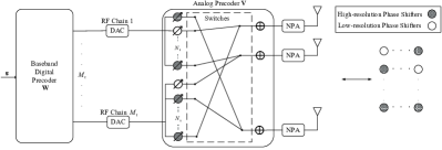
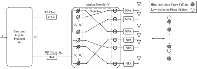
In this paper, we assume that the analog precoder is implemented with a TRPS network, which involves both high- and low-resolution phase shifters. Besides, the TRPS network can be classified into two common categories, widely known as the fully and the partially connected architectures. The categorization is based on the mapping of the signal vectors between the RF chains and the antennas, as illustrated in Fig. 1. The high- and low-resolution phase shifters in the TRPS network are implemented through - and -bit uniform quantizers [feng2020dynamic], respectively. Therefore, the total number of available discrete phases of the high- and low-resolution phase shifters are and , which are expressed respectively in the following sets
| (3) | ||||
| (4) |
The numbers of high- and low-resolution phase shifters are denoted as () and () for the fully and the partially connected architectures, respectively. More details for the aforementioned two architectures are shown in the following.
-
•
In the fully connected architecture, the analog precoder is equipped with phase shifters and each phase shifter is connected to switches, controlling the connections between the phase shifters and the antennas. We categorize the phase shifters attached to the same RF chain into one group and establish a corresponding phase shifter array whose pattern is detailed at the right end of Fig. 1(a). In this pattern, the element of the th column and th row represents the phase shifter connected to the th RF chain and the th antenna. The corresponding analog precoder is given by , where consists of the elements in the analog precoder connected to the th RF chain. The shadowed and hollow circles in the array stand for the high- and low-resolution phase shifters, respectively. We index the high- and low-resolution phase shifters according to their locations in the array and classify them into two sets and containing the index element of the phase shifters with high- or low-resolution, .
-
•
In the partially connected architecture, all the antennas are divided into groups, and each group includes elements connected to the same RF chains. A total of phase shifters are applied in this architecture, and each one of them is combined with switches to determine its connection to the antennas, as shown in Fig. 1(b). This strategy leads to a block diagonal structure for the analog precoder , where contains non-zero elements corresponding to the phase shifters in the network connected to the th RF chain. Note that, due to the diagonal block property of the desired matrix , the corresponding design can be converted into that of a vector defined as . Hence, the phase shifter array is compressed to one dimension, which is depicted at the right end of Fig. 1(b), and the index sets or are defined as the collection of the index corresponding to the th high- or low-resolution phase shifters, respectively, .
Remark 1
Based on the above discussion, the required numbers of the switches in the fully and partially connected architectures are and , respectively. The power consumption of the disabled switches can be neglected [guo2020energy] and we focus on the active switches. Therefore, the numbers of active switches in the fully and the partially connected architectures are and , respectively.
According to the above hybrid architecture, the expressions for the overall hybrid precoder is given by and where denotes the precoding vector for UT . Hence, the final precoded signal vector is defined as , where . Note that is distributed as where is given by . After that, the signal vector is amplified by the PAs before transmission. Assuming that each antenna is equipped with a PA and each PA has the same input-output relationship denoted by , the signal coming out of the th PA is given by [moghadam2018on], where denotes the complex th-order model coefficient. Hence, the instantaneous gain of the th PA is defined as
| (5) |