Resource Reduction in Multiplexed High-Dimensional Quantum Reed-Solomon Codes
Abstract
Quantum communication technologies will play an important role in quantum information processing in the near future as we network devices together. However, their implementation is still a challenging task due to both loss and gate errors. Quantum error correction codes are one important technique to address this issue. In particular, the Quantum Reed-Solomon codes are known to be quite efficient for quantum communication tasks. The high degree of physical resources required, however, makes such a code difficult to use in practice. A recent technique called quantum multiplexing has been shown to reduce resources by using multiple degrees of freedom of a photon. In this work, we propose a method to decompose multi-controlled gates using fewer gates via this quantum multiplexing technique. We show that our method can significantly reduce the required number of gates needed in the encoding circuits for the quantum Reed-Solomon code. Our approach is also applicable to many other quantum error correction codes and quantum algorithms, including Grovers and quantum walks.
I Introduction
Quantum communication systems utilizing the principles of superposition and entanglement will provide new capabilities that we can not achieve in our current telecommunication counterparts [1, 2, 3, 4, 5]. Such communication is expected to provide the basis for distributed quantum information processing systems, including quantum key distribution [6, 7], blind quantum computation [8, 9], distributed quantum computation [10], quantum remote sensing [11], and the quantum internet [12]. However, the fragile nature of quantum states as they propagate through such channels will severely limit the performance of the systems. Quantum error correction codes (QECCs) are a fundamental tool to address these issues as they can correct both channel loss and general errors (gate errors, for instance).
Since the first QECC was found by Shor [13], quite a number of codes have been proposed, including the stabilizer codes [14], quantum low-density parity-check codes [15], and GKP codes [16]. Further, the Calderbank-Shor-Steane (CSS) codes [17] are widely studied because they are quantum codes that can be constructed using a variety of classical codes and inherit the good properties of the existing classical codes [17]. For quantum computation, topological CSS codes, including the surface codes [18] have known useful properties such as high thresholds and capability of practical transversal gates due to the locality of stabilizers. For communication and memory, the delay introduced in the decoding is not as important as it is in computation [19], so complex decoding circuits are acceptable compared to those typically used in the computation. Therefore, for quantum communication and quantum memory-related tasks, code rate and minimum distance are more important than the locality of the stabilizers. It is known that the Quantum Reed-Solomon code [20] is one of the most efficient codes for quantum communication from that point of view.
The classical Reed-Solomon (RS) code [21] has been used in various communication systems [22, 23] due to it being a maximum distance separable (MDS) code [24]. MDS codes are important because they can detect and correct the greatest number of errors for a fixed codeword length and message length . In the RS code, multiple consecutive bits correspond to an element of a Galois Field (GF) [21]. This allows this code to be particularly resilient to a class of errors called burst errors (errors occurring in consecutive bits) [22], where multiple bits are used to represent a single element of the GF. Now the Quantum Reed-Solomon (QRS) codes [20] are known to be one of the most efficient CSS codes because of their excellent ability to correct qudit loss errors, which are the most critical issue in long-distance quantum communication in optics [25]. However, QECCs require significant physical sources (both in terms of the numbers of photons and qubits) for their realization, making their implementation quite challenging. Recently [26] it was shown that quantum multiplexing allows one to reduce the number of resources when applied to the redundancy code [27] and small scale QRS codes. This was achieved by using multiple degrees of freedom of the photon. Here we show that by using such quantum multiplexing techniques, we can drastically reduce the number of controlled-X () gates required to implement the encoding circuit of QRS codes that could be used in quantum communication tasks.
Now our paper is organized as follows. In Section II, we will present the construction of QRS codes and their coding circuits. We then briefly review in Section III the quantum multiplexing technique and propose a method to implement multiple controlled gates ( gates) using fewer gates by utilizing quantum multiplexing. Section IV then shows the degree of gate reduction that can be achieved when quantum multiplexing is applied to the encoding circuit of the QRS code. The results and applications of the proposed method to other quantum tasks are discussed in Section V.
II The Quantum Reed-Solomon Code
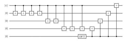
Let us begin with a brief overview of the Quantum Reed-Solomon code. The QRS code [20, 28, 29, 30] is defined by the CSS construction [17] of the classical RS code in which (a prime number) is the dimension of the qudits used to encode the logic states. Further, is the number of logical qudits, while is the minimum distance of the code. In our work, we will consider the case, which has the ability to retrieve the original encoded quantum information when or less qudits are lost. The encoding quantum circuit for the QRS code shown in Fig.1 can be implemented using a series of quantum SUM gates [16] and a discrete Fourier transform (DFT) gate [31]. The SUM gate is a generalization of the gate for -dimensional qudit and is given by:
where and are integers . Next the DFT gate is a generalization of the Hadamard gate, which when applied to a single qudit, creates a superposition of states given by:
To illustrate how these operations work, Fig.1 shows an example of the encoding circuit for the code.
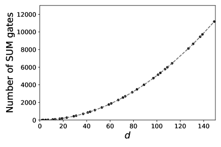
The number of SUM gates required to create the code using a -dimensional qudit is , and is plotted in Fig.2. This number increases quadratically with the qudit dimension. Further, the number of gates used in each SUM gate also increases with the qudit dimension (as we will show later), making the implementation of higher-dimensional QRS codes more difficult. For our purposes, it is more convenient to encode each logical -dimensional qudit of the QRS code with qubits where . The SUM gate is essentially a modulo adder and can be decomposed into two parts. The first part is the Ripple carry adder (RCA) [32] that performs the following transformation:
The second part is a modulo operation that performs the following transformation:
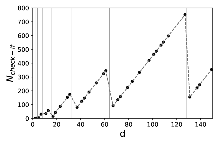
In such a case, the RCA part adds two binary numbers having bits. This part utilizes auxiliary qubits called “carry” to store the outcome of the addition of two qubits having both values . Further, the modulo operation can also be split into two distinct elements. In the first element, a series of logic gates check whether the outcome of the RCA exceeds . In that case, the result will be stored in an auxiliary qubit we label “check if”. A specific example of how these auxiliary qubits have been used is presented in Appendix A. The second element, which we label as a conversion element, transforms the output of the RCA part in representation to the desired output of the SUM gate with representation.
We need to consider this in a little more detail and so let us look at the various outcomes of the RCA, which correspond to our three different cases. In the first case, where the outcome of the RCA is less than , the conversion element will not change this outcome; hence no further action is needed. In the second case, where the outcome is greater than but less than , “check if” auxiliary qubits are used for storing each value. Those values are then used to convert the outcome to the desired state in the conversion element. In the third case, where the outcome is greater than or equal to , “check if” auxiliary qubits will be used to store each value, and the biggest “carry” qubit is also used to distinguish the value and the value minus in the conversion element. However, the “check if” qubit is not required when the outcome is if and only if . This is because the biggest “carry” can be used as the “check if” value since is the only one value that is bigger than . This SUM gate construction requires auxiliary qubits where -qubits are for the “carry” and qubits are for the “check if”.
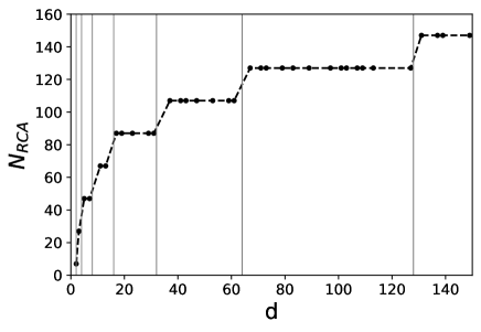
The total number of gates for each gate in a -qudit system with is given by: , where are the number of gates for the RCA (modulo) parts, respectively. The number of gates required by those are presented in the TABLE 1 where is the gate controlled by -qubits ( is controlled by and is the well known Toffoli gate), gate is the gate controlled by qubits + 1 “carry” auxiliary qubit.
| Condition | |||||
Now in Fig.3 we plot versus . Since the RCA part is a simple bit ripple carry adder, depends only on integer for which is shown as the gray line. When is sufficiently large, can be negligibly small compared to , and so is dominated by .
In the modulo conversion part, the gate can be decomposed into gates and the gate can be decomposed into gates as shown in [33]. Further the gate can be decomposed into , , and gates. We will refer to this decomposition as a “general decomposition” and compare it to our more efficient multiplexing decomposition later on. In the next section, we will show that applying quantum multiplexing can drastically reduce the number of gates required to implement these circuits. The details of the modulo adder implementation are described in Appendix A.
III Quantum Multiplexing
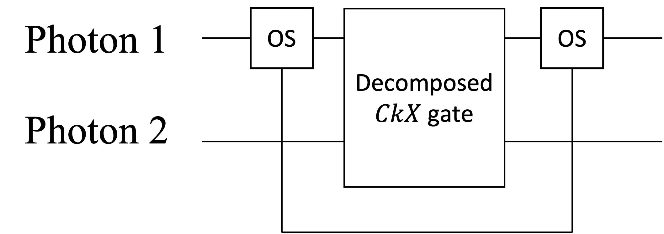
The quantum multiplexing technique [34] aims at reducing the number of physical resources needed for a quantum communication system by using multiple degrees of freedom (DOF) of the single-photon to carry and process information. For instance, applying quantum multiplexing to error correction codes permits one to reduce drastically the number of single photons and qubits required to encode the information shared by Alice and Bob [34]. Another remarkable feature of quantum multiplexing is that it enables us to substitute a Toffoli gate [35], which normally requires gates, with a single gate between two multiplexed photons (or no gates on a single photon). This is done by splitting one DOF of a photon into two separate spatial modes and applying a gate directly on one mode, as shown in Fig.4(a). So the natural question is how we apply it to our situation.
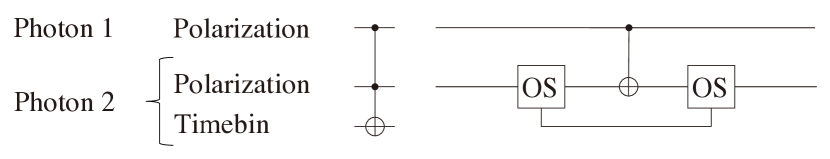
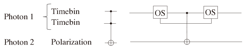
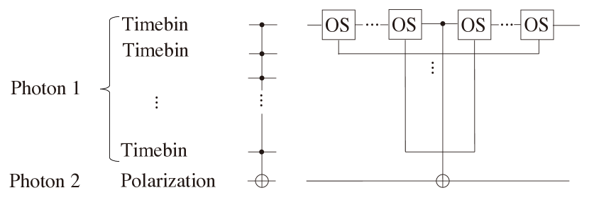
In our work, we first generalize this method to a gate between a photon having as control two timebins and another photon having as target the polarization DOF as shown in Fig.4(b). Furthermore, we generalize the result of [35] by assuming that we can also substitute the gate and the gate by a single and a gate respectively when quantum multiplexing is applied. To this aim, we require multiple optical switches OS (if the time-bin DOF is being used) to split each component belonging to the photon having multiple controls into single spatial modes. Then a single is applied between the relevant component and the target photon. Finally, a series of optical switches will restore the components into a single spatial mode, as shown in Fig.4(c). Our assumption can be proved by using the induction principle shown in Appendix C.
We use this result then to substitute each and gates required in the modulo conversion part of our encoding scheme with a single gate and gate, respectively. Note that requires a gate instead of a gate since has a control qubit in the auxiliary photon. We will refer to this decomposition as a “multiplexing decomposition”. This will considerably decrease the number of gates used, as we show in the next section.
IV Performance

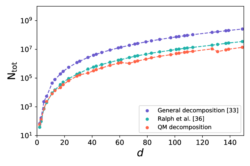
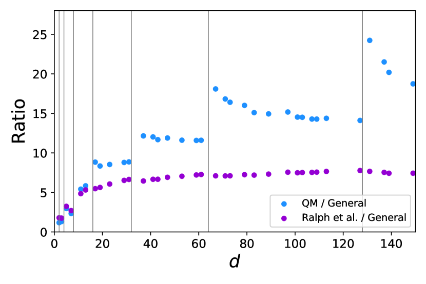
Our focus now will be to compare the number of gates required to encode a QRS code versus its dimension when single-mode photons and multiplexed photons are used. The blue (red) curve of Fig.5(a) shows the total number of gates required to implement a single SUM gate for a -dimensional QRS code when single-mode (multiplexed) photons are used. The blue curve increases rapidly with the dimension of the code reaching gates required for whereas the red curve increases modestly with the code dimension (using only at ). Thus, applying quantum multiplexing has resulted in a significant reduction in CX gates. Moreover, for the multiplexing case, at and the number of gates is slightly less than and , respectively. Although it seems an inconsistent result, it can be explained by looking at the second case of TABLE 1. The number of gates and the number of gates are present in the “check if” part of the modulo conversion scheme. They reduce to and gates when multiplexing is applied. Therefore, the total number of gates will be much more affected by than by These numbers depend on the number of qubits used to encode the states as well as on the dimension of the code, . When , we require several “check if” auxiliary qubits to implement the modulo addition meaning will be high. On the other hand, when will be the preponderant term as we can now e use more qubits for the sum and less “check if” qubits. Although it is not clear from Fig.5(a) we also have that This behavior is more evident in Fig.5(b), which shows the total number of gates required to construct the whole encoder. The gate reduction by quantum multiplexing is also significant in the overall cost of the encoding circuit. Regardless of the value of we always require a number of conversion gates proportional to the code dimension. Thus, the number of conversion gates represented by the Hamming distance in TABLE 1 is not a relevant term for determining the behavior.
Next Fig.5(c) shows the ratio of of the non-multiplexed case (blue) over the multiplexed case (red). It allows us to quantify the improvement we have. Here we can see that the curve “jumps” to a much higher ratio value when it crosses the gray lines, which correpond to with integer We label the prime numbers in which this happens by . At the ratio decreases as shown in regions ( to , to , and to ) of Fig.5(c). This is due to the higher number of required as increases as already explained in the previous paragraph. However, at the ratio increases slightly until due to the fact that for this range of the number of “check if” increases only slightly as shows in Fig.5(d). We also compare our results with the ones obtained by [36] shown by the magenta curves in Fig.5. In [36], the authors realize gates by introducing one k-dimensional qudit, two qubit gates and single qudit gates they refer to and . Our results still show an advantage compared to the ones proposed in [36] in terms of gate reductions. Furthermore, the system proposed in [36] require special gates and which might require more two-qubit gates when qubits representation is in use. We also determined that the encoding circuit for QRS codes where for integers does not require Toffoli or gates, hence quantum multiplexing does not give any advantage in terms of gates reduction for these special cases. We show in the Appendix B an example of an implementation of a QRS encoding circuit over GF().
There is a well-known method [37] for constructing efficient encoding circuits for stabilizer codes, but this method requires multiple-target gates but not multiple-controlled gates. Therefore, the proposed method cannot be directly applied to such encoding circuits. The proposed method can be applied to the encoding circuit of quantum error correcting codes using multiple controlled gates.
V Discussion
In this work, we have applied quantum multiplexing to the encoder of the Quantum Reed-Solomon and have shown that it is possible to dramatically reduce the number of controlled X gates utilized. Further, this method can be used to implement the encoder of QRS with fewer gates when the dimension of qudit is close to where is a prime number, and is greater than 6. This reduction of the number of gates should make the implementation of QRS codes more feasible - especially in the quantum communication setting. Another method of realizing gates is to decompose the gates directly into optical elements instead of or gates, which has been proposed in [38]. This method requires beam splitters with transmittance, mirrors, and phase shift for realizing multiple controlled-phase gates. For realizing gates in real physical systems, it is necessary to quantitatively evaluate various resources and compare multiple implementation methods.
Next, our approach can be applied to other error correction codes and quantum algorithms that require a large number of gates. For example, most of the cost of a quantum circuit implementation of a discrete-time quantum walk algorithm [39] is the unitary operator that walks a “quantum walker” in a certain space, called a Shift operator [40]. The circuit construction of the Shift operator depends on the space in which the quantum walk is performed (for instance, in a graph [41], one-dimensional space [42], or a hypercube [43]), but in many cases, they consist of multiple controlled quantum gates [44]. This is because the Shift operator depends on the state of the “quantum walker” at a certain time and transitions to the quantum state of the “quantum walker” at the next time step, and such dependence on the previous time is realized by control gates. A second example is Grover’s search algorithm [45]. The practical cost of Grover’s algorithm depends on the complexity of the unitary, called an “oracle”, which depends on the diffusion operator (inversion about the average). When the size of the search space is -qubits, it is common to use gates in the diffusion part [46].
To summarize, our paper shows that when quantum multiplexing is used, it is possible to significantly reduce the number of CX gates for the encoding circuits of QRS codes and important quantum algorithms. Future work includes optimization of circuits for correction and decoding of QRS codes and other QECCs.
Acknowledgements
SN acknowledge Min-Hsiu Hsieh from Foxconn Quantum Computing Center for useful discusssions throughout this project. This work was supported by JSPS KAKENHI Grant Number 21H04880, the MEXT Quantum Leap Flagship Program (MEXT Q-LEAP) Grant Number JPMXS0118069605, and the JST Moonshot R&D Grant Number JPMJMS2061.
References
- Munro et al. [2015] W. J. Munro, K. Azuma, K. Tamaki, and K. Nemoto, Inside quantum repeaters, IEEE Journal of Selected Topics in Quantum Electronics 21, 78 (2015).
- Duan et al. [2001] L.-M. Duan, M. D. Lukin, J. I. Cirac, and P. Zoller, Long-distance quantum communication with atomic ensembles and linear optics, Nature 414, 413 (2001).
- Jiang et al. [2009] L. Jiang, J. M. Taylor, K. Nemoto, W. J. Munro, R. Van Meter, and M. D. Lukin, Quantum repeater with encoding, Physical Review A 79, 032325 (2009).
- Lo and Chau [1999] H.-K. Lo and H. F. Chau, Unconditional security of quantum key distribution over arbitrarily long distances, science 283, 2050 (1999).
- Hwang [2003] W.-Y. Hwang, Quantum key distribution with high loss: toward global secure communication, Physical Review Letters 91, 057901 (2003).
- Bennett and Brassard [1984] C. H. Bennett and G. Brassard, Quantum cryptography: Public key distribution and coin tossing, arXiv preprint arXiv:2003.06557 (1984).
- Ekert [1991] A. K. Ekert, Quantum cryptography based on bell’s theorem, Physical Review Letters 67, 661 (1991).
- Arrighi and Salvail [2006] P. Arrighi and L. Salvail, Blind quantum computation, International Journal of Quantum Information 4, 883 (2006).
- Broadbent et al. [2009] A. Broadbent, J. Fitzsimons, and E. Kashefi, Universal blind quantum computation, in 2009 50th Annual IEEE Symposium on Foundations of Computer Science (IEEE, 2009) pp. 517–526.
- Cirac et al. [1999] J. Cirac, A. Ekert, S. Huelga, and C. Macchiavello, Distributed quantum computation over noisy channels, Physical Review A 59, 4249 (1999).
- Schanda [2012] E. Schanda, Physical fundamentals of remote sensing (Springer Science & Business Media, 2012).
- Kimble [2008] H. J. Kimble, The quantum internet, Nature 453, 1023 (2008).
- Shor [1995] P. W. Shor, Scheme for reducing decoherence in quantum computer memory, Physical Review A 52, R2493 (1995).
- Gottesman [1997] D. Gottesman, Stabilizer codes and quantum error correction, arXiv preprint quant-ph/9705052 (1997).
- MacKay et al. [2004] D. J. MacKay, G. Mitchison, and P. L. McFadden, Sparse-graph codes for quantum error correction, IEEE Transactions on Information Theory 50, 2315 (2004).
- Gottesman et al. [2001] D. Gottesman, A. Kitaev, and J. Preskill, Encoding a qubit in an oscillator, Physical Review A 64, 012310 (2001).
- Calderbank and Shor [1996] A. R. Calderbank and P. W. Shor, Good quantum error-correcting codes exist, Physical Review A 54, 1098 (1996).
- Kitaev [1997] A. Y. Kitaev, Quantum error correction with imperfect gates, in Quantum communication, computing, and measurement (Springer, 1997) pp. 181–188.
- Pierce [1965] W. H. Pierce, Failure-tolerant computer design (Academic Press, 1965).
- Grassl et al. [1999] M. Grassl, W. Geiselmann, and T. Beth, Quantum reed—solomon codes, in Applied Algebra, Algebraic Algorithms and Error-Correcting Codes (Springer, 1999) pp. 231–244.
- Reed and Solomon [1960] I. S. Reed and G. Solomon, Polynomial codes over certain finite fields, Journal of the Society for Industrial and Applied Mathematics 8, 300 (1960).
- Wicker and Bhargava [1999] S. B. Wicker and V. K. Bhargava, Reed-Solomon codes and their applications (John Wiley & Sons, 1999).
- Feng and Yuen [2006] Y. C. Feng and P. C. Yuen, Protecting face biometric data on smartcard with reed-solomon code, in 2006 Conference on Computer Vision and Pattern Recognition Workshop (CVPRW’06) (IEEE, 2006) pp. 29–29.
- MacWilliams and Sloane [1977] F. J. MacWilliams and N. J. A. Sloane, The theory of error correcting codes, Vol. 16 (Elsevier, 1977).
- Muralidharan et al. [2014] S. Muralidharan, J. Kim, N. Lütkenhaus, M. D. Lukin, and L. Jiang, Ultrafast and fault-tolerant quantum communication across long distances, Physical review letters 112, 250501 (2014).
- Piparo et al. [2020a] N. L. Piparo, M. Hanks, C. Gravel, K. Nemoto, and W. J. Munro, Resource reduction for distributed quantum information processing using quantum multiplexed photons, Physical Review Letters 124, 210503 (2020a).
- Ralph et al. [2005] T. C. Ralph, A. Hayes, and A. Gilchrist, Loss-tolerant optical qubits, Physical Review Letters 95, 100501 (2005).
- Ketkar et al. [2006] A. Ketkar, A. Klappenecker, S. Kumar, and P. K. Sarvepalli, Nonbinary stabilizer codes over finite fields, IEEE Transactions on Information Theory 52, 4892 (2006).
- La Guardia [2009] G. G. La Guardia, Constructions of new families of nonbinary quantum codes, Physical Review A 80, 042331 (2009).
- Muralidharan et al. [2018] S. Muralidharan, C.-L. Zou, L. Li, and L. Jiang, One-way quantum repeaters with quantum reed-solomon codes, Physical Review A 97, 052316 (2018).
- Grassl et al. [2003] M. Grassl, M. Rötteler, and T. Beth, Efficient quantum circuits for non-qubit quantum error-correcting codes, International Journal of Foundations of Computer Science 14, 757 (2003).
- Vedral et al. [1996] V. Vedral, A. Barenco, and A. Ekert, Quantum networks for elementary arithmetic operations, Physical Review A 54, 147 (1996).
- Barenco et al. [1995] A. Barenco, C. H. Bennett, R. Cleve, D. P. DiVincenzo, N. Margolus, P. Shor, T. Sleator, J. A. Smolin, and H. Weinfurter, Elementary gates for quantum computation, Physical Review A 52, 3457 (1995).
- Piparo et al. [2019] N. L. Piparo, W. J. Munro, and K. Nemoto, Quantum multiplexing, Physical Review A 99, 022337 (2019).
- Piparo et al. [2020b] N. L. Piparo, M. Hanks, K. Nemoto, and W. J. Munro, Aggregating quantum networks, Physical Review A 102, 052613 (2020b).
- Ralph et al. [2007] T. Ralph, K. Resch, and A. Gilchrist, Efficient toffoli gates using qudits, Physical Review A 75, 022313 (2007).
- Cleve and Gottesman [1997] R. Cleve and D. Gottesman, Efficient computations of encodings for quantum error correction, Physical Review A 56, 76 (1997).
- Fiurášek [2006] J. Fiurášek, Linear-optics quantum toffoli and fredkin gates, Physical Review A 73, 062313 (2006).
- Aharonov et al. [1993] Y. Aharonov, L. Davidovich, and N. Zagury, Quantum random walks, Physical Review A 48, 1687 (1993).
- Kempe [2003] J. Kempe, Quantum random walks: an introductory overview, Contemporary Physics 44, 307 (2003).
- Aharonov et al. [2001] D. Aharonov, A. Ambainis, J. Kempe, and U. Vazirani, Quantum walks on graphs, in Proceedings of the thirty-third annual ACM symposium on Theory of computing (2001) pp. 50–59.
- Ambainis et al. [2001] A. Ambainis, E. Bach, A. Nayak, A. Vishwanath, and J. Watrous, One-dimensional quantum walks, in Proceedings of the thirty-third annual ACM symposium on Theory of computing (2001) pp. 37–49.
- Moore and Russell [2002] C. Moore and A. Russell, Quantum walks on the hypercube, in International Workshop on Randomization and Approximation Techniques in Computer Science (Springer, 2002) pp. 164–178.
- Douglas and Wang [2009] B. Douglas and J. Wang, Efficient quantum circuit implementation of quantum walks, Physical Review A 79, 052335 (2009).
- Grover [1996] L. K. Grover, A fast quantum mechanical algorithm for database search, in Proceedings of the twenty-eighth annual ACM symposium on Theory of computing (1996) pp. 212–219.
- Lavor et al. [2003] C. Lavor, L. Manssur, and R. Portugal, Grover’s algorithm: Quantum database search, arXiv preprint quant-ph/0301079 (2003).
Appendix A Circuit implementation of the SUM gates (the Modulo adder)
This appendix describes the construction of a quantum circuit for a -dimensional SUM gate. The inputs of this gate are the pair of qubits and corresponding to the pair of -dimensional qudits, and the output is the modulo with respect to of the sum of the two inputs.
As described in Section II, the circuit consists of an RCA part and a modulo part. The RCA part adds the numbers of the same place in inputs and and stores the overflow of the place in the “carry” qubits for use in calculating the next place. Fig.6 shows what information is stored in which qubit during the calculation of the RCA part for .

Next the modulo circuit converts the state stored in to the state. Such a conversion is necessary for the case in which the sum of the inputs is between to . We prepare a “check if” qubit for each of the numbers from to , and then the “check if” qubit is flagged (flipped from to ) when the sum of the inputs in each corresponding values to . In order to perform such an operation, we perform gate with the data qubits as the control qubits with the corresponding “check if” qubit as the target qubit. At this time, we choose control and -control based on the binary representation of each number. For normal controls, the gate is applied to the target when the control qubit is , but for -control, the gate is applied when the control is . If one wants to invert the “check if” qubit for , use the control, -control, and control for . Next, when the sum cannot be a number greater than , the most significant carry can be used as the “check if” qubit of . In this case, the gate for “check if” qubit inversion is also unnecessary.
Consider the following example. If , then a conversion is required when the sum of the inputs is between and . Since ,… , no conversion is required for to . You can also substitute as a “check if” qubit of in this case. After the flip of the “check if” qubits, converts the data qubits based on the “check if” qubit. As an example, we execute controlled gates with “check if” qubit as control qubit for the conversion from , , , to , , , for .
It is important to note that when the maximum value that the sum can take is greater than , the largest “carry” qubit must be used as a control qubit at the same time. For example, in the case, the transformation is needed when the sum is between and . However, to determine that the sum is , not only must the data qubit be , but must be . This makes it necessary to use the gate instead of . Such gates can only be decomposed up to gates when multiplexing decomposition is used since the control qubits are in two qudits (data and carry). For the decomposition of gates to gates, we need to use the general method.
The case of constructing a modulo adder for the and dimensional qudit using multiplexed photon is shown in the Fig.7 and 8.


Appendix B The encoding circuit for the QRS codes
Let us consider the QRS code on with . This code construction is based on (written in binary form) for . To illustrate how this works let us take the code as a simple example. The Galois Field for the code is represented as
| (1) |
where we choose as the primitive polynomial. Then the elements of the field be written in polynomial and vector representation:
We use the classical code and it’s dual for our CSS construction. The generator polynomial for the code is given as
| (2) |
from which we get the generator and parity check matrices:
| (3) |
| (4) |
The quantum circuit for the encoder is shown in Fig.9
Now we denote the qudit gates required for our implementation as , , and defining them as follows:
| (5) | |||||
| (6) | |||||
| (7) |
These gates correspond to the addition and multiplication of Galois elements for the calculation of coefficients of polynomials in Quantum Reed-Solomon codes. They can be implemented in a multiplexing system as shown in the Fig.10. As such, the gates of can be constructed using only gates.
By generalizing the above method, we can calculate the cost of the gates we will need for implementing the QRS code. First the gate can be achieved with gates while the gates can be implemented with gates for the system where is a function whose input is an exponential representation of a element of the Galois Field and whose output is a Hamming weight of the vector representation of the element. In this case, we do not need the gate to implement the encoding circuit of the code. Therefore, the application of quantum multiplexing does not lead to any advantage in terms of the reduction of the number of gates.


Appendix C Proof for the multiplexed decomposition
Theorem.
A gate, which has control time-bin qubits in a photon and a target qubit in another photon, can be decomposed into a single gate alongside several optical switches.
Proof.
Let be the statement that the gate in the theorem can be decomposed into one gate and several optical switches.
We will now give a proof by induction on beginning with . Since gate is a gate from a control photon to a target photon, it holds by definition. Now for any integer , if holds, then also holds. Assume the induction hypothesis is true. Since the gate can be realized by controlling the gate with the ()-th timebin qubit, it can be decomposed as shown in Fig.11. From , the gate can be implemented with one and several OSs, therefore holds.

∎
Note that using the implementation of gate in the Appendix C of [35], the target qubit can be either polarization or timebin.