Spurious microwave crosstalk in floating superconducting circuits
Abstract
Crosstalk is a major concern in the implementation of large-scale quantum computation since it can degrade the performance of qubit addressing and cause gate errors. Finding the origin of crosstalk and separating contributions from different channels are essential prerequisites for figuring out crosstalk mitigation schemes. Here, by performing circuit analysis of two coupled floating transmon qubits, we demonstrate that, even if the stray coupling, e.g., between a qubit and the drive line of its nearby qubit, is absent, microwave crosstalk between qubits can still exist due to the presence of a spurious crosstalk channel. This channel arises from free modes, which are supported by the floating structure of transmon qubits, i.e., the two superconducting islands of each qubit with no galvanic connection to the ground. For various geometric layouts of floating transmon qubits, we give the contributions of microwave crosstalk from the spurious channel and show that this channel can become a performance-limiting factor in qubit addressing. This research could provide guidance for suppressing microwave crosstalk between floating superconducting qubits through the design of qubit circuits.
I Introduction
Integrating a growing number of qubits without scarifying quantum gate performance is a key task in the implementation of large-scale quantum computers with superconducting qubits Martinis2015 . One of the main obstacles that needs to be overcome, in this task, is crosstalk, including classical crosstalk due to unintended classical electromagnetic couplings Wenner2011 ; Martinis2014 ; Rosenberg2019 ; Patterson2019 ; Huang2021 ; Abrams2019 ; Dai2021 and quantum crosstalk arising from residual quantum coupling Patterson2019 ; Gambetta2012 ; Mundada2019 ; Wei2021 ; Zhao2022 , which can make qubit addressing a challenge Gambetta2012 and degrade gate performance in multiqubit quantum processors Sarovar2020 . In this context, the progress in understanding and mitigating crosstalk has made indispensable contributions to the impressive achievements toward developing large-scale superconducting quantum computing over the past decade.
One of the most ubiquitous crosstalk for superconducting quantum processors is the microwave crosstalk, which describes that microwave drives applied to one qubit can cause unintended drives felt by the others. To address this issue, various active cancelation methods, i.e., one first characterizes it and then cancels it actively with a compensation drive, have been demonstrated Sung2021 ; Nuerbolati2022 . Nevertheless, mitigating the crosstalk at device level may complement existing active approaches and further reduce the needed physical resource, especially for large-scale quantum processors. Indeed, previous works show that the crosstalk can be suppressed at the device level, but only if the origin of the crosstalk and contributions from different crosstalk channels are well understood Wenner2011 ; Huang2021 .
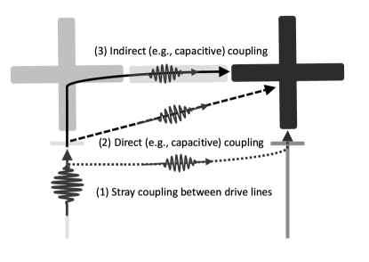
Generally, to implement universal control over qubits in quantum processors, at least a single drive line (drive channel) per qubit is needed. Hence, as shown in Fig. 1, there are three possible microwave crosstalk channels in superconducting quantum processors, including (Type-1) stray coupling between the dedicated drive lines of qubits, the direct (Type-2) and the indirect (Type-3) coupling between one qubit and the drive line of others. For large-scale quantum processors, a high density of control wiring is required, thus the crosstalk through the first two channels could become more serious Wenner2011 ; Rosenberg2019 ; Huang2021 . Generally, the two channels can be mitigated by improving the physical isolation between drive lines and qubits Rosenberg2019 . For the Type-3 channel, however, its physical origin and mitigation seems to be more nontrivial. In principle, its origin can be modeled by the indirect coupling between one qubit and the drive line of the others through an effective circuit network Solgun2019 . Physically, the circuit network could arise from the presence of package modes or chip modes Wenner2011 ; Rosenberg2019 , and could even relate to the qubit itself Johnson2011 ; Galiautdinov2012 . Nevertheless, the exact nature of this circuit network and its contribution to the microwave crosstalk are less studied.
In this work, we present a spurious microwave crosstalk channel (Type-3) enabled by the presence of free modes in floating transmon circuits Kerman2020 ; Ding2021 ; Long2020 ; Koch2007 . By performing circuit analysis of coupled floating transmon qubits with different geometric layouts Paik2020 ; Rahamim2017 ; Mamin2022 , we show that the microwave crosstalk contributed from this spurious channel can become non-negligible, thus potentially limiting the performance of qubit addressing. More importantly, this crosstalk channel only depends on the qubit circuit itself, thus acting as an intrinsic channel, which can exist even when the stray coupling, e.g., between drive lines and qubits, is absent. This feature also suggests that this spurious channel can be mitigated through qubit circuit design.
This paper is organized as follows. In Sec. II, we analyze the quantum circuit of two direct-coupled floating transmon qubits (in the Appendix we further extended our analysis to the case, where floating transmon qubits are coupled via a grounded or floating bus coupler) and show that the presence of the free modes can induce a spurious microwave crosstalk channel. In Sec. III, for transmon qubits with different qubit geometric layouts, we give the contributions of microwave crosstalk from the spurious channel. In Sec. IV, we give discussions on the relation of the free-mode-mediated spurious crosstalk channel in our work with the free-mode mediated inter-qubit interactions illustrated in two recent works Sete2021 ; Yanay2022 and show that the present work can be viewed as complements to the two earlier works, extending the free-mode mediated interactions from ”quantum regime” (for inter-qubit coupling) to ”semi-classical regime” (for classical microwave crosstalk). Finally, in Sec. V, we provide a summary of our work.
II spurious microwave crosstalk channel
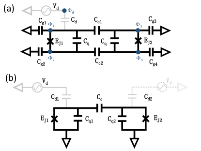
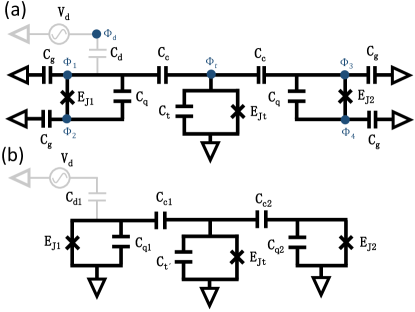
To understand the origin of the spurious microwave crosstalk channel, we consider a superconducting circuit comprising two direct-coupled floating transmon qubits ( and ), and one of the two qubits () is coupled capacitively to a voltage source, as shown in Fig. 2(a). When expressed in terms of the node flux variables and with the magnetic flux quantum, the circuit Lagrangian is given by (details on its derivation can be found in Appendix A) Yanay2020 ; Vool2017
| (1) |
where with and , and are the Josephson energies, and denotes the capacitance matrix of the circuit. Accordingly, the circuit Hamiltonian can be constructed as with the charge variables . Here, the modes associated with the variables and are the qubit modes, which have both the charge energy and the potential energy Koch2007 , while the modes associated with and , and which don’t have potential terms in the Hamiltonian, are the free modes Kerman2020 ; Ding2021 ; Long2020 . From the derivation and also mentioned in previous works Kerman2020 ; Ding2021 ; Long2020 , the presence of the free modes are supported by the floating structure of transmon qubits, i.e., the two superconducting islands of the qubit have no galvanic connection to the ground, as shown in Fig. 2(a), contributing to an additional quantum degree of freedom.
Since free modes actually don’t participate in the circuit dynamics Kerman2020 ; Ding2021 ; Long2020 , one can drop the charge terms corresponding to the two free modes and rewrite the circuit Hamiltonian as
| (2) |
with . Here, denotes the reduced capacitance matrix, which can also be used to describe a circuit system consisting of two direct-coupled grounded transom qubits, as shown in Fig. 2(b) (see Appendix A for details). Here, for illustration purpose, considering a typical case where all the island capacitors take a same capacitance, i.e., and both the island capacitance and the shunt capacitance largely exceed the coupling capacitances, i.e., , the matrix can be approximated by
| (3) |
Inspecting , one can find that both the matrix elements and , which describe the coupling between the two qubit modes and the external voltage source, take nonzero values. This means that although in the original circuit, only one of the two qubits is coupled to the voltage source, here, both of the two qubits are coupled to the voltage source simultaneously. As a consequence, after dropping the free modes, the full circuit shown in Fig. 2(a) can be transformed into an equivalent circuit shown in Fig. 2(b). The most striking result from the equivalence is that due to the presence of the free modes, a spurious microwave crosstalk channel can exist, even if the stray coupling between qubits and drive lines is absent.
To quantify the crosstalk through the spurious channel, we consider the crosstalk strength defined as , expressed in units of dB. Here, denotes the magnitude of the microwave drive applied to a target qubit (e.g., ), while represents the magnitude of the crosstalk felt by the other nearby qubit (e.g., ). For a grounded transmon qubit coupled to an external voltage source via a coupling capacitor , the magnitude of the drive can be approximated by with the zero-point charge fluctuations and the qubit impedance Sank2014 . and correspond to the qubit inductance and capacitance, respectively. For illustration purposes only, we further assume that both qubits have the same qubit inductances and capacitances, thus in the system shown in Fig. 2(a), the strength of the spurious microwave crosstalk from to can be expressed by
| (4) |
with the ratio given by
| (5) |
As shown in Eq. (5), the spurious crosstalk only depends on the qubit circuit parameters, thus acting as an intrinsic crosstalk channel. Moreover, since in coupled qubit circuits, the coupling capacitors, e.g., and , generally have a rather small capacitance, which is typical of the order of a few or less, the spurious crosstalk can be suppressed through increasing the island capacitance. However, depending on the qubit geometric layout, the island capacitance can take a wide range of values, typically, ranging from a few fFs to . Hence, as we will show below, the spurious crosstalk can become non-negligible, thus limiting the performance of qubit addressing.
While here we focus on the direct-coupled qubit system, in Appendices B and C, we also extend the above analysis to the indirect-coupled qubit systems, including floating qubits coupled through a grounded bus or a floating bus. We find that the spurious crosstalk channel disappears for floating qubits coupled via the grounded bus, while it still exists for qubits coupled via the floating bus. This opposite conclusions further demonstrate that the presence of the spurious crosstalk is mediated by the free modes in the qubit circuit. In addition, for floating qubits coupled by the grounded bus, the analysis also shows that the grounded bus can also feel the drive applied to the floating qubit, i.e., a spurious crosstalk channel between the floating qubit and the grounded bus is existent. Thus, we conclude that for the crosstalk from to in the system shown in Fig. 2(a), this spurious crosstalk is in fact mediated by the free mode supported by the driven qubit , and it will still exist even if is a grounded one.
| Geometric layout |
|
|
||||||
|---|---|---|---|---|---|---|---|---|
|
|
|
||||||
|
|
|
III spurious microwave crosstalk in typical floating transmon circuits
The above discussion indicates that the spurious crosstalk channel is intrinsic, and its strength only depends on the qubit circuit parameters, i.e., the concrete qubit geometric layout. Here, to study this geometric dependence, we consider that for the coupled qubit system shown in Fig. 2(a), and , thus giving rise to
| (6) |
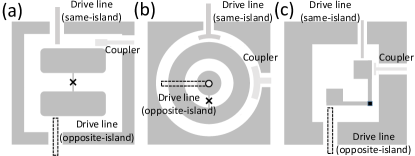
Thus, according to the ratio of the two island capacitances (hereafter we refer to it as the island asymmetric ratio), there are two main island geometric layouts for floating transmon qubits, i.e., symmetry layout and asymmetry layout. For example, the traditional floating transmon qubits have two same islands Paik2020 , as shown in Fig. 3(a), thus acting as a symmetric one, while for the coaxial transmon Rahamim2017 , as shown in Fig. 3(b), its two islands have different geometric designs, thus it belongs to the asymmetric one.
Additionally, note that in principle, the drive line and the coupler (e.g., the capacitors and ) could be coupled to one of the two islands or both of the two islands simultaneously, as shown in Fig. 2(a). However, for practically implemented floating qubit circuits, as shown in Fig. 3, generally, the drive line and the coupler are dominantly coupled to one of the two islands. Hence, as shown in Fig. 3, here we consider two coupling geometric layouts, i.e., the drive line could be coupled capacitively to the same island or the opposite island with respect to the coupling island, which is coupled capacitively to the other nearby qubits. For example, in Fig. 2(a), when and , the coupling geometric layout is a same-island one, while for and , it is an opposite-island case.
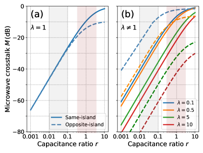
According to the above mentioned island geometric layout (symmetric v.s. asymmetric) and coupling geometric layout (same-island v.s. opposite-island), Table 1 lists the expressions of the crosstalk strengths for four different qubit geometric layouts. Accordingly, Figure 4 shows the crosstalk strengths as a function of the capacitance ratio , i.e., the ratio of the coupling capacitance to the island capacitance. As shown in Fig. 4(a), for the traditional floating transmon qubits, where the island capacitance is generally far larger than the coupling capacitance, thus the spurious crosstalk can be entirely suppressed below, e.g., , regardless of the coupling geometric layout. However, for the floating merged-element transmon qubit (MET) with a symmetric layout Mamin2022 , where the island capacitance can be comparable to or even smaller than the coupling capacitance, the spurious channel can become the dominated microwave crosstalk source. In this situation, the magnitude of the spurious crosstalk can even be comparable to that of the target dive. In addition, compared to the case of the same-island layout, qubits with the opposite-island layout, especially for the floating MET qubits, can show a less pronounced spurious crosstalk, typically below .
Figure 4(b) shows the spurious crosstalk strength for qubits with the asymmetric island layout. One can find that generally larger island asymmetric ratio can mitigate the spurious crosstalk, and can become even more noticeable when taking the opposite-island layout. Thus, for the coaxial transmon shown in Fig. 3(b), when the drive line is coupled to the center island and inter-qubit coupling is realized via the outer island, the spurious crosstalk could be readily suppressed below . Moreover, while the spurious channel acts as a significant source of the crosstalk for the MET qubits with the symmetric island layout, by taking the opposite-island layout and increasing the island asymmetric ratio, the spurious crosstalk is promising to be pushed below .
Given the state-of-the-art values of the microwave crosstalk in multiqubit quantum processors, typically ranging from to for neighboring control lines Gong2021 ; Ren2022 , we conclude that: (i) for the traditional floating transmon qubits with symmetric island layout, as shown in Fig. 3(a), the spurious crosstalk can be ignored safely if the island capacitance largely exceeds the coupling capacitance. (ii) for the floating transmon qubits with asymmetric island layout, such as the coaxial transmon shown in Fig. 3(b), taking a larger asymmetric ratio could help to suppress the spurious crosstalk. This suppression can become more prominent when employing the opposite-island layout. (iii) for the floating MET qubits with symmetric island layout, as shown in Fig. 3(c), the spurious crosstalk is less readily suppressed. Nevertheless, similar to the coaxial transmon, the combination of the asymmetric island layout and the opposite-island layout will hopefully lead to adequate suppression of the spurious crosstalk.
IV discussion
Recently, two independent works show that the free mode can mediate an indirect inter-qubit coupling Sete2021 ; Yanay2022 . In Ref.Sete2021 , Sete et al. have demonstrated that for qubits coupled via a floating tunable coupler (i.e., an additional frequency-tunable floating transmon qubit), the free mode due to the floating structure of the coupler can induce an indirect inter-qubit coupling, for which its strength only depends on the circuit capacitance, rather than the coupler frequency. Thus, combined with the coupler mediated dispersive coupling, tunable coupling between qubits can be realized by adjusting the coupler frequency Sete2021 ; Yan2018 . Similarly, in Ref.Yanay2022 , Yanay et al. have shown that in an array of floating transmon qubits, the free mode can mediate interactions between next-nearest neighbor qubits and even beyond next-nearest neighbors. The strength of the mediated interaction can be engineered via circuit design. Similarly, our results show that the free mode can also mediate cross-driving, enabling the presence of an additional intrinsic crosstalk channel. Hence, our analysis can be viewed as complements to the two earlier works, extending the free-mode mediated interactions from ”quantum regime” (for inter-qubit coupling) to ”semi-classical regime” (for spurious microwave crosstalk). Moreover, by extending to this semi-classical regime, it is also reasonable to expect that the floating transmon qubit can also relax through the control lines of its coupled neighbors.
V conclusion
In summary, by performing circuit analysis of two coupled floating transmon qubits, we have demonstrated that the free mode, which is supported by the floating structure of qubits, can induce a spurious microwave crosstalk channel. Depending on the actual qubit geometric layout, the spurious crosstalk can become non-negligible, and can even limit the performance of qubit addressing. Thus, to ensure higher-fidelity qubit addressing, the spurious crosstalk needs to be carefully considered. To address it, we have also shown that for various typical floating transmon circuits, the spurious crosstalk can be largely suppressed through circuit design.
Although our present analysis of the spurious crosstalk focuses on the floating transmon qubits, we expect that the analysis and many of the results may also be applied to other types of superconducting circuits with floating islands, such as flux qubits Orlando1999 and fluxonium qubits Manucharyan2009 .
Acknowledgements.
We acknowledge helpful discussions with Huihai Zhao and Zhenyu Mi. This work was supported by the National Natural Science Foundation of China (Grants No.11890704, No.12104055, No.12004042, No.12104056), the Beijing Natural Science Foundation (Grant No.Z190012), and the Key-Area Research and Development Program of Guang Dong Province (Grant No. 2018B030326001).Appendix A Direct Capacitor
Here, we consider two floating qubits coupled via direct capacitors, as shown in Fig. 2(a). The Lagrangian of the circuit can be expressed in terms of the node flux variables with , as denoted in Fig. 2(a), and is given as Vool2017
| (7) |
where where and are the Josephson energies, with the magnetic flux quantum, , and the capacitance matrix, given as
| (8) |
with
| (9) | ||||
To identify and remove the free modes in the circuit, we consider the following transformation of the node flux variables with respect to the transformation matrix Yanay2020
| (10) |
After performing the transformation, the circuit Lagrangian now reads
| (11) |
Here, the transformed node flux variables is , where and , and the corresponding capacitance matrix is now given as . Then, the circuit Hamiltonian can be expressed as Vool2017
| (12) |
where denotes the charge variable, which is conjugated to the node flux variable with . Here, the modes associated with and , and which don’t have any potential energies in the circuit Hamiltonian, are the free modes Kerman2020 ; Ding2021 ; Long2020 .
As discussed in previous works, the free modes actually don’t participate in the circuit dynamics Kerman2020 ; Ding2021 ; Long2020 . Hence, one can drop the terms associated with the free modes in the circuit Hamiltonian in Eq. (12), giving rise to
| (13) |
where , denotes the reduced capacitance matrix, which can also be used to describe a system consisting of two direct-coupled grounded transom qubits, as shown in Fig. 2(b). Here, for illustration purpose and to avoid the extremely cumbersome expression of , we consider that all the island capacitor take the same capacitance, i.e., . In this case, the expression of is given by (since is a symmetric matric, hereafter, the elements in the lower triangular parts of the capacitance matrix, denoted by , are not given explicitly)
| (14) |
where
| (15) |
| (16) |
| (17) | ||||
| (18) | ||||
When the island capacitance and the shunt capacitance is far larger than the coupling capacitance, i.e., , the reduced capacitance matrix can be approximated by
| (19) |
Appendix B Grounded Bus
Here, as shown in Fig. 5(a), we consider that two floating transmon qubits coupled via a grounded bus. Following the same procedure given in Appendix A, the circuit in Fig. 5(a) can be reduced to the circuit in Fig. 5(b), where two grounded transmon qubits are coupled via a grounded bus. After removing free modes, the reduced capacitance matrix of the current circuit is given by (here, the charge variables are , and the corresponding flux variables are with and )
| (20) |
where
| (21) | ||||
and
| (22) | ||||
When considering that , the above matrix can be approximated by
| (23) |
As shown in Eq. (20), for qubits coupled via the grounded bus, the spurious crosstalk disappears, i.e., the matrix element, which represents the coupling between the drive source and the , takes the value of , i.e., . This is to be expected since the grounded bus does not support the presence of free mode, thus there are no free modes to mediate the spurious crosstalk between the two qubits.
In addition, note that the matrix element gets a nonzero value, as shown in Eq. (20). This means that there exists a spurious crosstalk channel between the qubit and the grounded bus (in Fig. 5(b), the corresponding virtual drive line is not presented explicitly). Thus, we can conclude that this spurious crosstalk channel is mediated by the free mode supported by the qubit .
Appendix C Floating Bus

Here, as shown in Fig. 6(a), we consider that two floating transmon qubits coupled via a floating bus Sete2021 . Following the same procedure given in Appendix A, the circuit in Fig. 6(a) can be transformed into an equivalent circuit shown in Fig. 6(b), where two grounded transmon qubits are coupled via a coupler circuit combining a grounded bus and a capacitor Sete2021 ; Yan2018 . Accordingly, the reduced capacitance matrix of the present circuit is given by (here, the charge variables are , and the corresponding flux variables are with , , and )
| (24) |
where
| (25) | ||||
| (26) |
| (27) | ||||
| (28) | ||||
| (29) | ||||
When considering that , the above matrix can be approximated by
| (30) |
As shown in Eq. (24), for qubits coupled via the floating bus, the spurious crosstalk between the two qubits exists due to the presence of the free mode supported by the floating bus. Moreover, as demonstrated in previous works Sete2021 ; Yanay2022 , the free mode, which is supported by the floating bus, can also mediate an indirect coupling between the two qubits.
References
- (1) J. M. Martinis, Qubit Metrology for Building a Fault Tolerant Quantum Computer, npj Quantum Inf. 1, 15005 (2015).
- (2) J. Wenner, M. Neeley, R. C. Bialczak, M. Lenander, E. Lucero, A. D. ÓConnell, D. Sank, H. Wang, M. Weides, A. N. Cleland, and J. M. Martinis, Wirebond cross talk and cavity modes in large chip mounts for superconducting qubits, Supercond. Sci. Technol. 24, 065001 (2011).
- (3) J. M. Martinis and A. Megrant, UCSB final report for the CSQ program: Review of decoherence and materials physics for superconducting qubits, arXiv:1410.5793.
- (4) D. Rosenberg, S. Weber, D. Conway, D. Yost, J. Mallek, G. Calusine, R. Das, D. Kim, M. Schwartz, W. Woods, J. L. Yoder, and W. D. Oliver, 3D integration and packaging for solid-state qubits, arXiv:1906.11146.
- (5) A.D. Patterson, J. Rahamim, T. Tsunoda, P.A. Spring, S. Jebari, K. Ratter, M. Mergenthaler, G. Tancredi, B. Vlastakis, M. Esposito, and P.J. Leek, Calibration of a Cross-Resonance Two-Qubit Gate Between Directly Coupled Transmons, Phys. Rev. Appl. 12, 064013 (2019).
- (6) S. Huang, B. Lienhard, G. Calusine, A. Vepsäläinen, J. Braumüller, D. K. Kim, A. J. Melville, B. M. Niedzielski, J. L. Yoder, B. Kannan, T. P. Orlando, S. Gustavsson, and W. D. Oliver, Microwave Package Design for Superconducting Quantum Processors, PRX Quantum 2, 020306 (2021).
- (7) D. M. Abrams, N. Didier, S. A. Caldwell, B. R. Johnson, and C. A. Ryan, Methods for Measuring Magnetic Flux Crosstalk between Tunable Transmons, Phys. Rev. Applied 12, 064022 (2019).
- (8) X. Dai, D. M. Tennant, R. Trappen, A. J. Martinez, D. Melanson, M. A. Yurtalan, Y. Tang, S. Novikov, J. A. Grover, S. M. Disseler, J. I. Basham, R. Das, D. K. Kim, A. J. Melville, B. M. Niedzielski, S. J. Weber, J. L. Yoder, D. A. Lidar, and A. Lupascu, Calibration of flux crosstalk in large-scale flux-tunable superconducting quantum circuits, PRX Quantum 2, 040313 (2021).
- (9) J. M. Gambetta, A. D. Córcoles, S. T. Merkel, B. R. Johnson, John A. Smolin, J. M. Chow, C. A. Ryan, C. Rigetti, S. Poletto, T. A. Ohki, M. B. Ketchen, and M. Steffen, Characterization of Addressability by Simultaneous Randomized Benchmarking , Phys. Rev. Lett. 109, 240504 (2012).
- (10) P. S. Mundada, G. Zhang, T. Hazard, and A. A. Houck, Suppression of Qubit Crosstalk in a Tunable Coupling Superconducting Circuit, Phys. Rev. Applied 12, 054023 (2019).
- (11) K. X. Wei, E. Magesan, I. Lauer, S. Srinivasan, D. F. Bogorin, S. Carnevale, G. A. Keefe, Y. Kim, D. Klaus, W. Landers, N. Sundaresan, C. Wang, E. J. Zhang, M. Steffen, O. E. Dial, D. C. McKay, and A. Kandala, Quantum crosstalk cancellation for fast entangling gates and improved multi-qubit performance, arXiv:2106.00675.
- (12) P. Zhao, K. Linghu, Z. Li, P. Xu, R. Wang, G. Xue, Y. Jin, and H. Yu, Quantum Crosstalk Analysis for Simultaneous Gate Operations on Superconducting Qubits, PRX Quantum 3, 020301 (2022).
- (13) M. Sarovar, T. Proctor, K. Rudinger, K. Young, E. Nielsen, and R. Blume-Kohout, Detecting crosstalk errors in quantum information processors, Quantum 4, 321 (2020).
- (14) Y. Sung, L. Ding, J. Braumüller, A. Vepsäläinen, B. Kannan, M. Kjaergaard, A. Greene, G. O. Samach, C. McNally, D. Kim, A. Melville, B. M. Niedzielski, M. E. Schwartz, J. L. Yoder, T. P. Orlando, S. Gustavsson, and W. D. Oliver, Realization of High-Fidelity CZ and ZZ-Free iSWAP Gates with a Tunable Coupler, Phys. Rev. X 11, 021058 (2021).
- (15) W. Nuerbolati, Z. Han, J. Chu, Y. Zhou, X. Tan, Y. Yu, S. Liu, and F. Yan, Cancelling microwave crosstalk with fixed-frequency qubits, arXiv:2204.02946.
- (16) F. Solgun, D. DiVincenzo, and J. Gambetta, Simple Impedance Response Formulas for the Dispersive Interaction Rates in the Effective Hamiltonians of Low Anharmonicity Superconducting Qubits, IEEE Trans. Microw. Theory Tech. 67, 928 (2019).
- (17) B. R. Johnson. Controlling Photons in Superconducting Electrical Circuits. PhD thesis, Yale University, May 2011.
- (18) A. Galiautdinov, A. N. Korotkov, and J. M. Martinis, Resonator-zero-qubit architecture for superconducting qubits, Phys. Rev. A 85, 042321 (2012).
- (19) A. J. Kerman, Efficient numerical simulation of complex Josephson quantum circuits, arXiv:2010.14929.
- (20) D. Ding, H.-S. Ku, Y. Shi, and H.-H. Zhao, Free-mode removal and mode decoupling for simulating general superconducting quantum circuits, Phys. Rev. B 103, 174501 (2021).
- (21) J. Long, Superconducting Quantum Circuits for Quantum Information Processing. PhD thesis. University of Colorado, Boulder, 2020.
- (22) J. Koch, T. M. Yu, J. Gambetta, A. A. Houck, D. I. Schuster, J. Majer, A. Blais, M. H. Devoret, S. M. Girvin, and R. J. Schoelkopf, Charge-insensitive qubit design derived from the cooper pair box, Phys. Rev. A 76, 042319 (2007).
- (23) H. Paik, S. Srinivasan, S. Rosenblatt, J. Chavez-Garcia, D. Bogorin, O. Jinka, G. Keefe, D. Shao, J.-B. Yau, M. Brink, and J. M. Chow, Coupler characterization of superconducting transmons qubits for cross-resonance gate, 2020 IEEE International Electron Devices Meeting (IEDM), 2020, pp. 38.2.1-38.2.4.
- (24) J. Rahamim, T. Behrle, M. J. Peterer, A. Patterson, P. A. Spring, T. Tsunoda, R. Manenti, G. Tancredi, and P. J. Leek, Double-sided coaxial circuit QED with out-of-plane wiring, Appl. Phys. Lett. 110, 222602 (2017).
- (25) H. J. Mamin, E. Huang, S. Carnevale, C. T. Rettner, N. Arellano, M. H. Sherwood, C. Kurter, B. Trimm, M. Sandberg, R. M. Shelby, M. A. Mueed, B. A. Madon, A. Pushp, M. Steffen, and D. Rugar, Merged-Element Transmons: Design and Qubit Performance, Phys. Rev. Appl. 16, 024023 (2021).
- (26) E. A. Sete, A. Q. Chen, R. Manenti, S. Kulshreshtha, and S. Poletto, Floating Tunable Coupler for Scalable Quantum Computing Architectures, Phys. Rev. Appl. 15, 064063 (2021).
- (27) Y. Yanay, J. Braumüller, T. P. Orlando, S. Gustavsson, C. Tahan, and W. D. Oliver, Mediated Interactions beyond the Nearest Neighbor in an Array of Superconducting Qubits, Phys. Rev. Appl. 17, 034060 (2022).
- (28) Y. Yanay, J. Braumüller, S. Gustavsson, W. D. Oliver, and C. Tahan, Two-dimensional hard-core Bose-Hubbard model with superconducting qubits, npj Quantum Inf. 6, 58 (2020).
- (29) U. Vool and M. Devoret, Introduction to quantum electromagnetic circuits, Int. J. Circuit Theory Appl. 45, 897 (2017).
- (30) D. T. Sank, Fast, accurate state measurement in superconducting qubits, Ph.D. thesis. University of California, Santa Barbara, 2014.
- (31) M. Gong, S. Wang, C. Zha, M.-C. Chen, H.-L. Huang, Y. Wu, Q. Zhu, Y. Zhao, S. Li, S. Guo et al., Quantum walks on a programmable two-dimensional 62-qubit superconducting processor, Science 372, 948 (2021).
- (32) W. Ren, W. Li, S. Xu, K. Wang, W. Jiang, F. Jin, X. Zhu, J. Chen, Z. Song, P. Zhang et al., Experimental quantum adversarial learning with programmable superconducting qubits, arXiv:2204.01738.
- (33) F. Yan, P. Krantz, Y. Sung, M. Kjaergaard, D. L. Campbell, T. P. Orlando, S. Gustavsson, and W. D. Oliver, Tunable Coupling Scheme for Implementing High-Fidelity Two-Qubit Gates, Phys. Rev. Appl. 10, 054062 (2018).
- (34) T. P. Orlando, J. E. Mooij, L. Tian, Caspar H. van der Wal, L. S. Levitov, S. Lloyd, and J. J. Mazo, Superconducting persistent-current qubit, Phys. Rev. B 60, 15398 (1999).
- (35) V. E. Manucharyan, J. Koch, L. I. Glazman, and M. H. Devoret, Fluxonium: Single Cooper-pair circuit free of charge offsets, Science 326, 113 (2009).