Estimating Particle Size for Therapeutic Application of Boron in Proton Therapy using the Finite Element Method
Abstract
Previous measurements have shown large cross sections for the \ce^11B(p,α)^8Be reaction and K-shell ionization of boron from \ceH^+ ions. Past publications have shown that this reaction will likely increase the efficacy of proton therapy. This study investigates the size of boron particles for optimum treatment enhancement in proton therapy. Simulations of protons passing through varying sized boron particles were developed to compare energy outputs for alpha particles and low energy electrons. The results for the boron particle radius that produced the largest radiation output are presented in graphical form in this paper. The radius that produced the largest Auger output was determined to be . The results indicate that maximum dose enhancement will depend on the limiting factors of the biological system in regards to the appropriately sized particle. Studying different reactions that may be applied in hadron therapies allows researchers and physicians to target tumor sites more selectively.
keywords:
Proton therapy, Proton-boron reaction, Auger1 Introduction
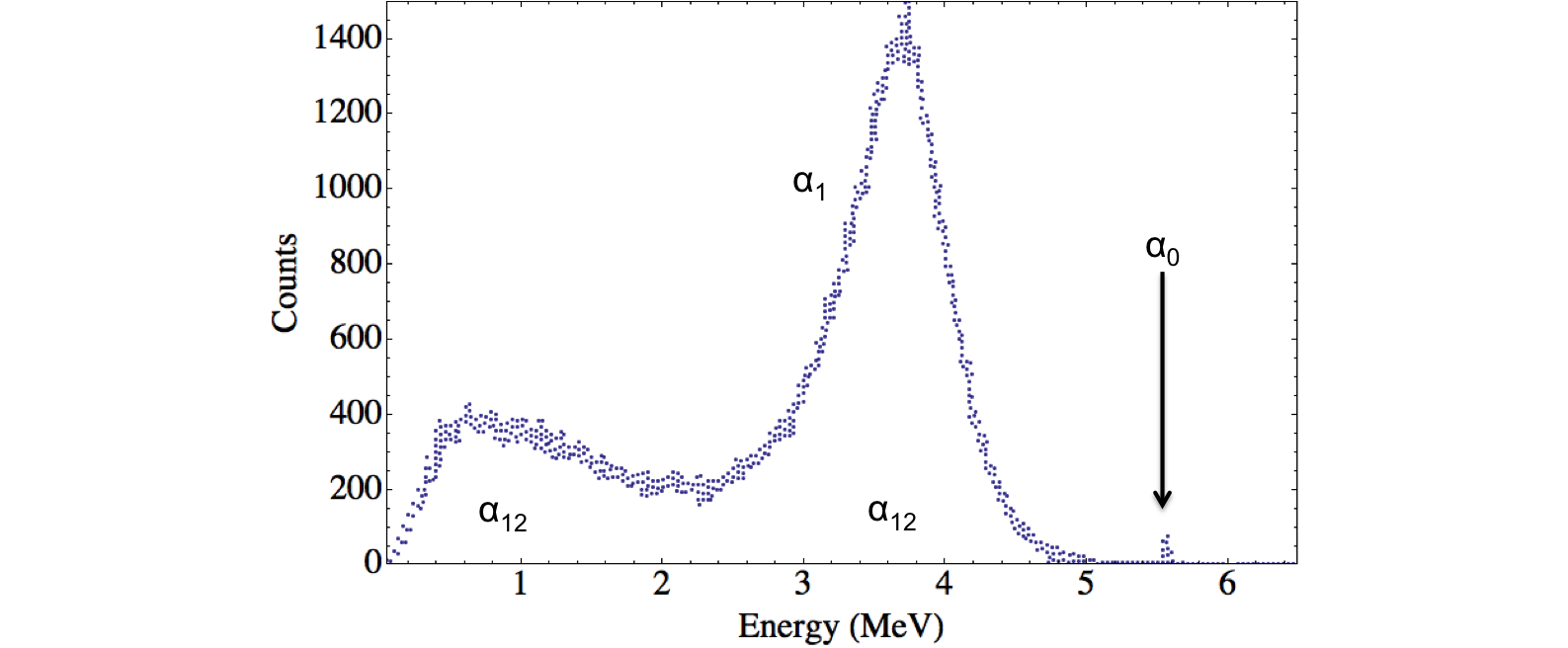
Over the last few decades there has been increased interest in further improving radiation therapies. More than 50% of patients with localized malignant tumors undergo radiation treatment as a component of their medial care [1]. A critical challenge in radiation oncology is how to better target tumor volumes while minimizing risks to normal healthy tissue. One method involves delivering an element or compound to the area of interest then utilizing nuclear reactions for dose enhancement. This process has been used in boron neutron capture therapy (BNCT) in which is irradiated with low energy thermal neutrons to yield high linear energy transfer (LET) alpha particles and nuclei [2, 3]. More recently there has been growing interest in the use of platinum and gold nanoparticles in radiotherapies [4, 5]. The nanoparticles can act as radiosensitizers by producing low energy electrons and x rays upon ionization that cause single and double DNA strand breaks in a target volume [6]. The electrons also induce water radiolysis and production of ∘OH hydroxyl radical clusters. These free radicals produce further breaks in the DNA [7]. Due to the limited range of the electrons the Auger electron cascade may benefit ion beam radiotherapies by enhancing the dose in targeted regions. Nanoparticles may be advantageous in creating secondary electrons arising out of Auger cascades utilizing high Z (atomic number) atom excitation. However, dense high Z materials also possess a high stopping power for low-energy electrons. This high stopping power may hinder electrons from escaping the nanoparticles to the targeted tissue and thus limit their effectiveness. Boron (z = 5) is a metalloid with a high Auger electron yield per electron from KLL ionization. Boron delivery agents are already being studied in BNCT [3, 2]. While these characteristics show promise in enhancing radiotherapy, it must be considered that the boron, in nanoparticle form, may absorb a significant amount of electron energy, effectively “self-shielding” the site from treatment. In addition to the Auger effect, boron particles may also undergo the \ce^11B(p,α)^8Be reaction [8]. Previous studies show that proton boron fusion therapy(PBFT) enhances dose in targeted tissue [9, 10]. This reaction produces three alpha particles through the two channels shown here and in Figure 1:
| (1) |
| (2) |
| (3) |
| (4) |
Alpha particles have ten times the radiation weighting factor in tissue of protons and twenty times the radiation weighting factor of photons [11]. The proton-boron reaction is exothermic with a Q value totaling 9.506 MeV. A large cross section is found at a broad resonance peak at 660 keV. These characteristics make this reaction attractive for enhancing proton therapy. [12]
Another type of therapy, embolization therapy, involves the introduction of small particles into tissue to reduce the blood flow to elicit vascular blockade and promote tumor necrosis. Embolization has also been used with drugs or chemotherapy, in which case it is known as chemoembolisation. Benefits from embolization therapies are dependent on blood supply, which limits the types of tissue treated. Embolic agents have been primarily investigated in treating liver cancers, though the method shows promise in the treatment of pancreatic cancer and breast cancer [13]. Embolization therapy could in principle be used in combination with PBFT to treat these cancers by using \ce^11B microparticles. The efficacy of this approach would depend on what sized boron particle yields the greatest radiation dose to the surrounding tissue.
The aim of this study is to simulate and compare this useful radiation energy output for differing sized boron particles under proton bombardment. This simulation will allow us to better assess what sized boron particle will produce the greatest dose enhancement in proton therapy. These results will assist medical physicists in selecting a boron particle size to study for clinical analysis.
2 Methods
Mathematica [14] provided the environment used to program the \ce^11B(p,α)^8Be and Auger simulations for varying boron particle sizes. These codes can be found on GitHub at [15]. The objective of each simulation was to find the size of spherical boron particle resulting in the greatest amount of energy deposition to the surrounding medium. The energy of each escaping alpha particle was totaled into a summation termed “alpha energy product.” Similarly, the total escaping electron energy was termed “electron energy product.” Each simulation used a two-dimensional polar scattering geometry with results suitably weighted to translate to three dimensions.
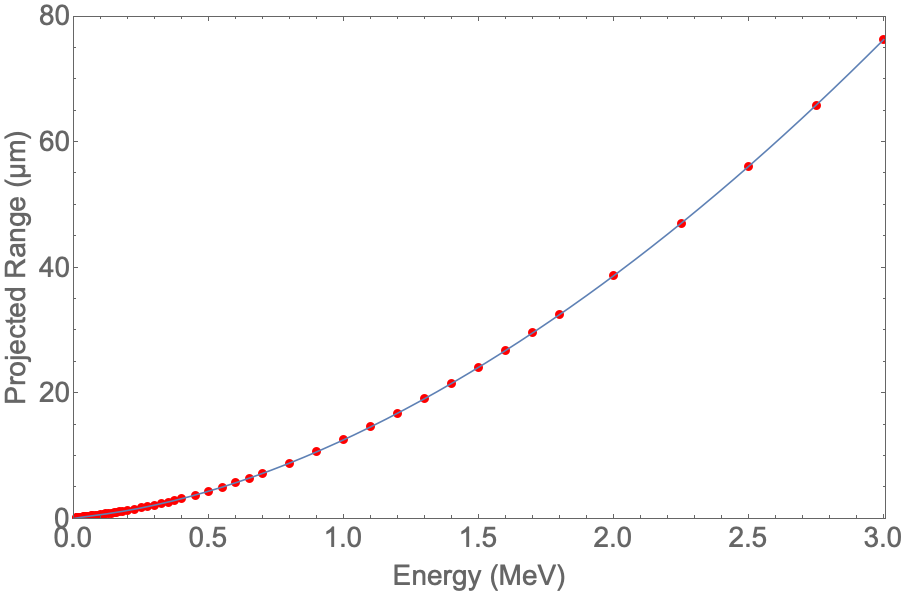
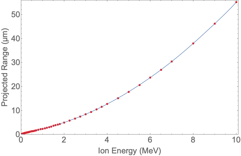
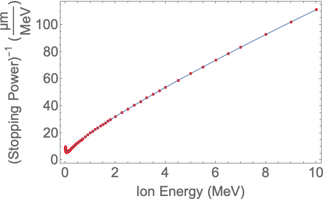
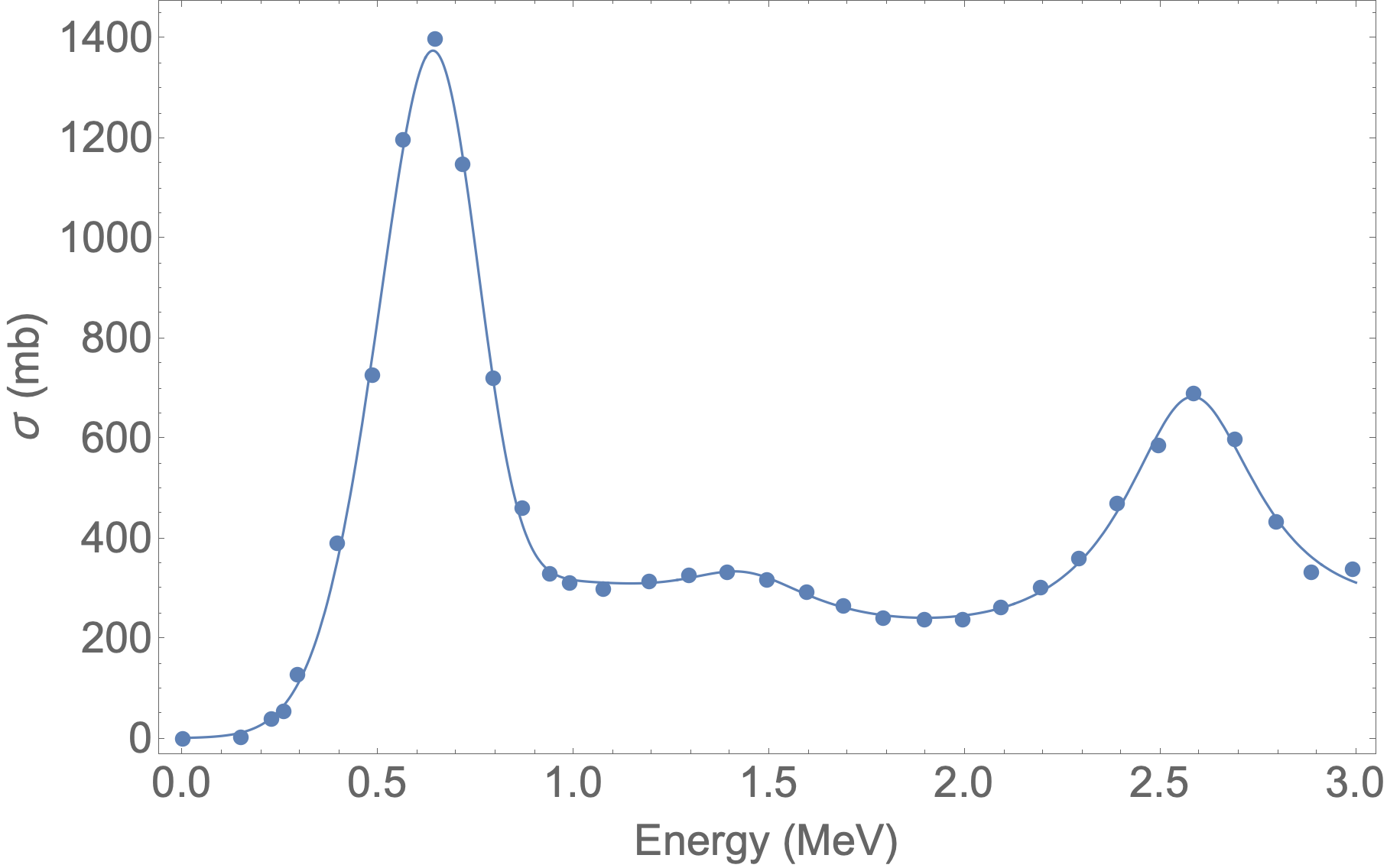
SRIM (The Stopping and Range of Ions in Matter) was used for both proton and alpha particle energy loss estimations and stopping power calculations in all materials [16]. Datasets for projected ranges, stopping powers, cross sections and related quantities were modeled with Mathematica’s NonlinearModelFit function. The results of these fits for the proton-boron reaction are shown in Figure 2 through Figure 5.
The \ce^11B(p,α)^8Be reaction’s angular dependent differential cross section, , was provided by Sikora [17]. Angular dependence of the differential cross sections were fitted with a Legendre polynomial expansion in the center of mass frame and scaled. Coefficients based on energy were provided in tabulated form. Cross section can have a significant effect on reaction rates and therefore simulation results. Previous existing cross section data can have errors up to 30% and inconsistencies as high as 50% [12]. More than 95% of Sikora’s individual data points were within 3% of the fitted results.
2.1 Simulating \ce^11B(p,α) 2α Reaction
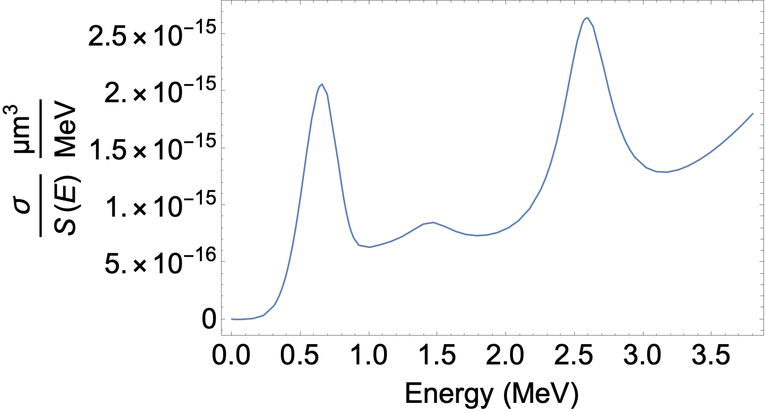
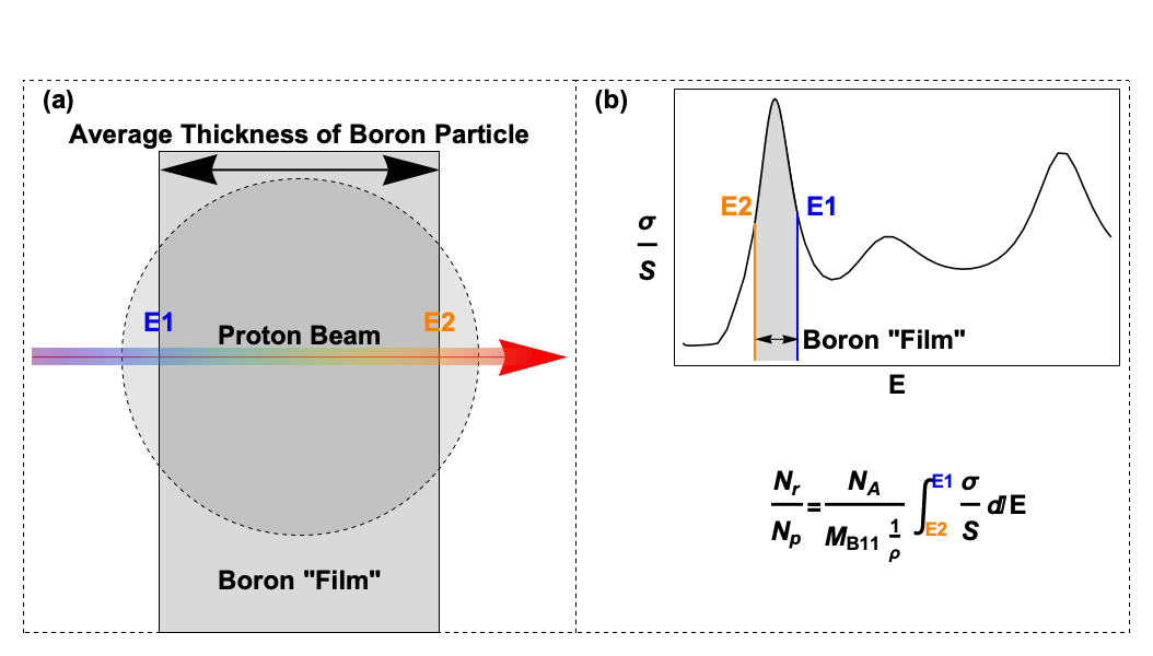
Creating an accurate simulation of the reaction requires taking into account every proton’s energy loss as it traverses a particle, every possible direction each alpha particle could travel, and creating enough reactions to be statistically significant. The purpose of this simulation was to compare the alpha-energy products of different-sized boron particles and in so doing used several approximation techniques. The average thickness of a given boron particle along the proton beam direction, where is the particle radius, was utilized in calculating average energy loss for an incident proton beam traversing the boron particle, thus replacing the spherical particle with an equivalent film of uniform thickness. Incident proton energies () were varied to produce the greatest number of alphas per proton for a given boron particle radius using Equation 5 below. The ratio of total cross section to stopping power that was used as the integrand in Equation 5 is shown in Figure 6. This energy-optimizing process is illustrated in Figure 7. Exiting proton () energies were determined by the size of boron particle and the protons’ average energy loss from traversing the boron particle. and were chosen so that they bracketed the peak in the reaction cross section at keV. Particle radii were varied between and . Collisions from the protons in the boron film were modeled using single scattering by the film [18] with the film being sufficiently thin that multiple scattering need not be considered. The reaction fractions (reactions per proton, ) were computed using a ratio of the total reaction cross section () and stopping power () as well as Avogadro’s number (), molar mass (), and mass density () in the equation:
| (5) |
The reaction fraction will vary for different regions within the boron particle because of changing proton energy. To account for this, the particle was divided into concentric cells with different radii. The region of interest between two radii within the boron particle for alpha generation is termed a cell. Equation 5 was used in two different ways, first to find and for the entire boron particle, and then to find the reaction fraction for each cell (with different and ). The reaction fraction for a sphere of radius subtracted from that for a sphere of radius gives the reaction fraction of the cell between and as shown in the equation:
| (6) |
Our simulation divided each boron particle into 20 cells.
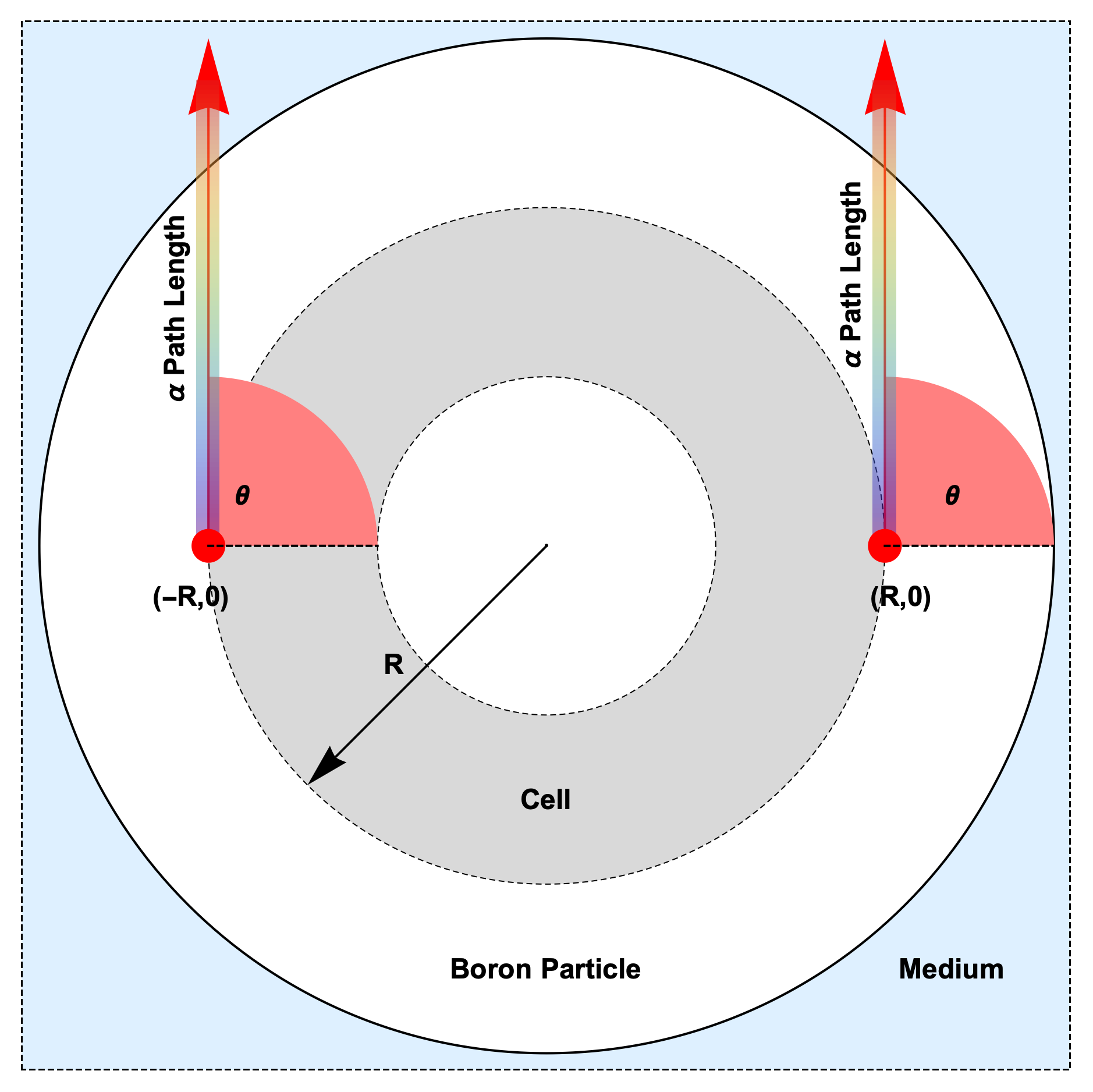
As mentioned before, the purpose of this simulation was to compare relative energy outputs to the medium surrounding a boron particle. Due to its broad peak in the alpha energy spectrum as seen in Figure 1, was selected as the representative reaction product to compare reactions at given proton energies and angles relative to the proton beam’s direction. The other reaction products are not included, and so the calculation doesn’t give total absolute energy deposition in tissue. The effect of the total energy deposition will be approximately twice that calculated for due to the way energy is distributed among the alphas for the reaction. Calculations were carried out for groups of alpha particles emitted in different directions at various depths in the boron particle. Each \ceα group’s energy calculations used the average proton incident energy at that depth. Eight alpha emission angles in the center of mass frame were then selected at equally-spaced intervals from 30∘ to 160∘. The emission angle and proton energy were used to determine the cross section. The energy loss of the exiting alpha particles calculation was based on traversed distance from the particle’s origin to the surface of the boron particle. The \ce^11B(p,α)^8Be reactions were simulated at cell points, defined to be at the location of the proton beam’s entrance and exit of each cell region on the x-axis as seen in Figure 8.
The algorithm itself performs the following steps:
1. Select boron particle radius and angles in the center of mass frame and radii by user. Radii were selected from to in steps.
2. Calculate average thickness of boron particle. This corresponds to a film.
3. Vary and find the incident proton energy and exiting proton energy that produce the maximum number of alpha particles using .
4. Divide the radius of the current boron particle into uniform intervals to define the radii of 20 concentric spheres. Convert these concentric spheres into inner films using the average thickness of each concentric sphere.
5. Determine the energy of the proton at the entrance and exit of each inner film. Use these energies to calculate the number of alphas generated at each inner film.
6. Calculate the incident and exiting energy of a proton passing through each inner film. Use these energies and angles in the lab frame to calculate the energy of \ceα_1 in this direction from [17].
7. Calculate the energy lost by alpha particles from the nodes to the surface of the spherical boron particle.
8. Add up the energies of escaping alpha particles multiplied by the number of alpha particles generated at each inner sphere and the counts/cross section for each angle in the lab frame for angular weighting.
9. Select a new radius for the boron particle and repeat the calculation for the new radius.
2.2 Simulating Auger Effect
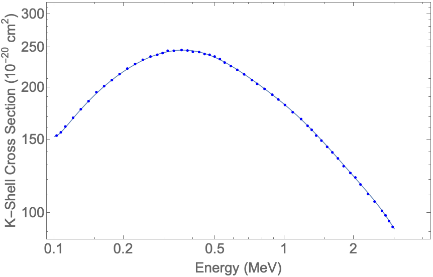
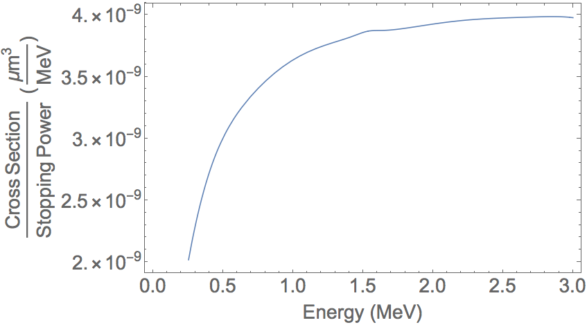
A simulation was written to compare electron energy outputs for varying sized boron particles. This simulates escaping low energy electrons caused by Auger cascades. Reaction fractions for various cells were calculated in the same way as the \ce^11B(p,α) 2α reaction simulation, but here using Auger production cross sections. Incident proton energies were varied from 0-3 MeV. The Energy-Loss Coulomb-Repulsion Perturbed-Stationary-State Relativistic(ECPSSR) theory [19, 20, 21], as shown in Figure 9, was used to estimate the K-shell ionization cross sections. The graphical representation of the K-shell cross section divided by proton stopping power is shown in Figure 10. All generated electrons were assumed to have a starting energy of 155 eV based on previously published measurements [19].
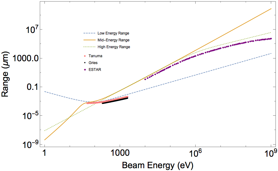
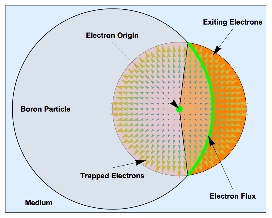
Because all electrons were assumed to have the starting energy of 155 eV this simulation used average Auger path length. This is the average length that electrons would need to travel to escape the boron particle from the node with an energy . The average path length for each node was then implemented in calculating the energy of escaping electrons. This region of electron flux for the escaping electrons is marked in Figure 12. Electron range in boron was approximated using the function developed by Wilson and Dennison [22]. The function was found to be suitable for over six orders of magnitude in energy with an uncertainty of for most conducting, semiconducting, and insulating materials. The simulation implemented Wilson’s mid-energy range approximation for projected range. Each range of electrons in boron is shown in Figure 11.
3 Results
3.1 \ce^11B(p,α) 2α Reaction
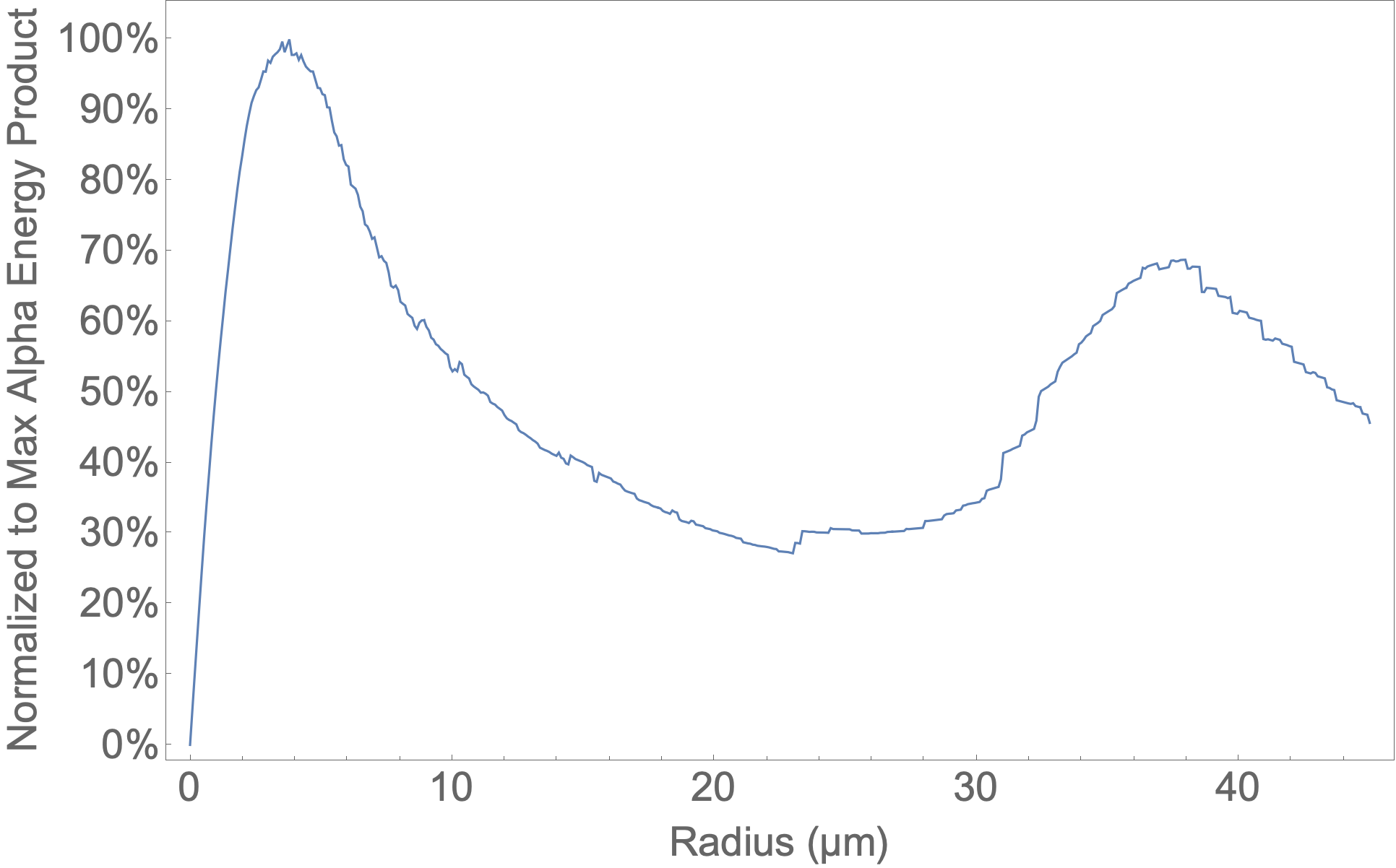
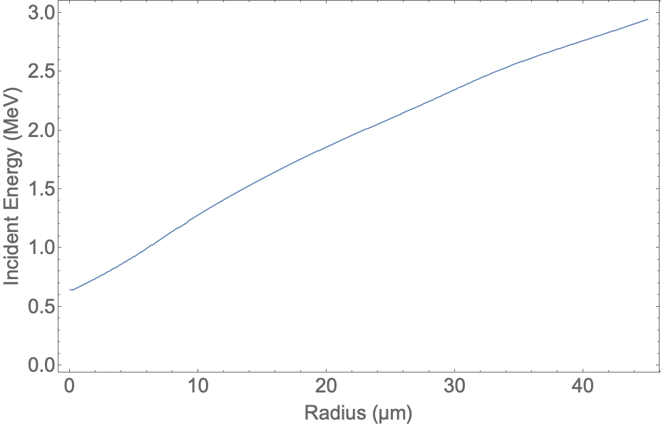
Figure 13 shows the alpha energy product that exits the boron particle normalized to the maximum output as a percentage vs. the radius. As the radius of boron increased, so did the alpha energy product until the size of the boron particle began shielding the treatment site, resulting in a maximum alpha energy product at a particle radius of and again at . It would take around 12643 protons to generate an alpha particle for the r = boron particle and 2960 protons for the r = boron particle. These peaks are associated with with the excitation of the two resonances in the reaction at 660 keV and 2.6 MeV. The average incident proton energy for each boron radius that produces the greatest number of alphas is shown in Figure 14.
3.2 Auger Effect
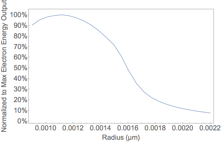
Figure 15 shows the electron energy deposited in the surrounding medium as a percentage of the maximum value. The radius of boron particle that had the greatest electron energy product was determined to be 1.1 nm. One reaction would require on average 40 protons for a boron particle at this size.
4 Conclusions
The size of the boron particle to maximize alpha dose depends on the limiting range of the biological system. Energy output can increase with radius until . This size is slightly over the limit for rigid particles passing through the small capillaries: d = [26].
The second peak, at , occurs over the particle radius size requirement for embolization therapy: [27]. This boron particle size could be investigated for use in combination with embolization therapy. While the alpha energy product may not be maximized at this size, blood restriction may contribute to increasing the treatments efficacy for certain types of liver cancer.
PBFT is a promising new treatment method that may one day be implemented to increase the efficacy of proton therapy [28, 29, 9]. This study only investigated the boron particle that will produce maximum energy output. Our results will need to be verified experimentally and clinically evaluated on the effect of increased absorbed dose of the surrounding target site.
The boron particle size to maximize the electron energy product, radius 1.1 nm, is under the size of abundant small pores present in normal tissue endothelium [26]. The energy of the electrons limit their range to 1.12-1.17 nm around the particle [30].
The average energy of Auger electrons simulated was 155 eV which is higher than those used in [31] which had lower than 100 eV for electrons produced in Au and Pt. This study limited its investigation to only simulating maximum energy output as it relates to particle size. Future work could experimentally study the surviving fraction of cells in boron-treated colonies with optimum sized boron particles and proton irradiation. More biological studies are needed to verify its effectiveness.
References
- [1] J. S. Loeffler, M. Durante, Charged particle therapy–optimization, challenges and future directions., Nature reviews. Clinical oncology 10 (7) (2013) 411–424. doi:10.1038/nrclinonc.2013.79.
- [2] S.-I. Miyatake, S. Kawabata, R. Hiramatsu, T. Kuroiwa, M. Suzuki, N. Kondo, K. Ono, Boron Neutron Capture Therapy for Malignant Brain Tumors., Neurologia medico-chirurgica (2016) 361–371doi:10.2176/nmc.ra.2015-0297.
- [3] R. F. Barth, J. A. Coderre, M. G. H. Vicente, T. E. Blue, Boron neutron capture therapy of cancer: Current status and future prospects, Clinical Cancer Research 11 (11) (2005) 3987–4002. doi:10.1158/1078-0432.CCR-05-0035.
- [4] E. Porcel, S. Liehn, H. Remita, N. Usami, K. Kobayashi, Y. Furusawa, C. L. Sech, S. Lacombe, Platinum nanoparticles: A promising material for future cancer therapy?, Nanotechnology 21 (8). doi:10.1088/0957-4484/21/8/085103.
- [5] J. F. Hainfeld, D. N. Slatkin, H. M. Smilowitz, The use of gold nanoparticles to enhance radiotherapy in mice, Physics in Medicine and Biology 49 (18). doi:10.1088/0031-9155/49/18/N03.
- [6] C. Champion, Quantum-mechanical predictions of electron-induced ionization cross sections of DNA components, Journal of Chemical Physics 138 (18). doi:10.1063/1.4802962.
- [7] N. USAMI, K. KOBAYASHI, R. HIRAYAMA, Y. FURUSAWA, E. PORCEL, S. LACOMBE, C. L. SECH, Comparison of DNA Breaks at Entrance Channel and Bragg Peak Induced by Fast C6+ Ions, Journal of Radiation Research 51 (1) (2010) 21–26. doi:10.1269/jrr.09035.
- [8] H. J. Meyer, U. Titt, R. Mohan, Technical note: Monte Carlo study of the mechanism of proton–boron fusion therapy, Medical Physics 49 (1) (2022) 579–582. doi:10.1002/mp.15381.
- [9] G. A. Cirrone, L. Manti, D. Margarone, G. Petringa, L. Giuffrida, A. Minopoli, A. Picciotto, G. Russo, F. Cammarata, P. Pisciotta, F. M. Perozziello, F. Romano, V. Marchese, G. Milluzzo, V. Scuderi, G. Cuttone, G. Korn, First experimental proof of Proton Boron Capture Therapy (PBCT) to enhance protontherapy effectiveness, Scientific Reports 8 (1). doi:10.1038/s41598-018-19258-5.
- [10] S. Kim, D.-K. Yoon, H.-B. Shin, J.-Y. Jung, M.-S. Kim, K.-H. Kim, H.-S. Jang, T. Suh, A simulation study for radiation treatment planning based on the atomic physics of the proton-boron fusion reaction, Journal of the Korean Physical Society 70 (6). doi:10.3938/jkps.70.629.
- [11] A. D. Wrixon, New ICRP recommendations, Journal of Radiological Protection 28 (2) (2008) 161–168. doi:10.1088/0952-4746/28/2/R02.
- [12] J. Liu, X. Lu, X. Wang, W. K. Chu, Cross-sections of 11B(p,)8Be reaction for boron analysis, Nuclear Instruments and Methods in Physics Research, Section B: Beam Interactions with Materials and Atoms 190 (1-4) (2002) 107–111. doi:10.1016/S0168-583X(01)01272-1.
- [13] T. Taguchi, Chemo-Occlusion for the Treatment of Liver Cancer, Clinical Pharmacokinetics 26 (4) (1994) 275–291. doi:10.2165/00003088-199426040-00004.
- [14] Wolfram Research Inc, Mathematica (2019).
- [15] J. Baxley, PBFT Particle Size Simulation, https://github.com/JacobBaxley/PBFT_Particle_Size_Simulation.
- [16] J. F. Ziegler, J. P. Biersack, M. D. Ziegler, SRIM, the Stopping and Range of Ions in Matter, SRIM Co, 2008.
- [17] M. H. Sikora, H. R. Weller, A New Evaluation of the 11B(p, ) Reaction Rates, Journal of Fusion Energy 35 (3) (2016) 538–543. doi:10.1007/s10894-016-0069-y.
- [18] R. D. Evans, The Atomic Nucleus, in: The Atomic Nucleus, Krieger Publishing Company, 1955.
- [19] W. M. Ariyasinghe, D. Powers, Absolute K -shell ionization cross-section measurements of B produced by 0.4–2.0-MeV H + and He + ions and by 0.6–1.2-MeV H 2 + ions, Physical Review A 59 (2) (1999) 1291–1296. doi:10.1103/PhysRevA.59.1291.
- [20] W. Brandt, G. Lapicki, L -shell Coulomb ionization by heavy charged particles, Physical Review A 20 (2) (1979) 465–480. doi:10.1103/PhysRevA.20.465.
- [21] W. Brandt, G. Lapicki, Energy-loss effect in inner-shell Coulomb ionization by heavy charged particles, Physical Review A 23 (4) (1981) 1717–1729. doi:10.1103/PhysRevA.23.1717.
- [22] G. Wilson, J. R. Dennison, Approximation of range in materials as a function of incident electron energy, in: IEEE Transactions on Plasma Science, Vol. 40, 2012, pp. 291–297. doi:10.1109/TPS.2011.2176515.
- [23] M. Berger, J. Coursey, M. Zucker, J. Chang, Stopping-Power and Range Tables for Electrons, Protons, and Helium Ions — NIST, NIST Standard Reference Database 124.
- [24] S. Tanuma, C. J. Powell, D. R. Penn, Calculations of electron inelastic mean free paths. V. Data for 14 organic compounds over the 50–2000 eV range, Surface and Interface Analysis 21 (3) (1994) 165–176. doi:10.1002/sia.740210302.
- [25] W. H. Gries, A universal predictive equation for the inelastic mean free pathlengths of x-ray photoelectrons and auger electrons, Surface and Interface Analysis 24 (1) (1996) 38–50. doi:10.1002/(SICI)1096-9918(199601)24:1<38::AID-SIA84>3.0.CO;2-H.
- [26] Y. H. Bae, K. Park, Targeted drug delivery to tumors: Myths, reality and possibility, Journal of Controlled Release 153 (3) (2011) 198–205. doi:10.1016/j.jconrel.2011.06.001.
- [27] P. Bastian, R. Bartkowski, H. Köhler, T. Kissel, Chemo-embolization of experimental liver metastases. Part I: Distribution of biodegradable microspheres of different sizes in an animal model for the locoregional therapy, European Journal of Pharmaceutics and Biopharmaceutics 46 (3) (1998) 243–254. doi:10.1016/S0939-6411(98)00047-2.
- [28] P. Bláha, C. Feoli, S. Agosteo, M. Calvaruso, F. P. Cammarata, R. Catalano, M. Ciocca, G. A. P. Cirrone, V. Conte, G. Cuttone, A. Facoetti, G. I. Forte, L. Giuffrida, G. Magro, D. Margarone, L. Minafra, G. Petringa, G. Pucci, V. Ricciardi, E. Rosa, G. Russo, L. Manti, The Proton-Boron Reaction Increases the Radiobiological Effectiveness of Clinical Low- and High-Energy Proton Beams: Novel Experimental Evidence and Perspectives, Frontiers in Oncology 11. doi:10.3389/FONC.2021.682647/FULL.
- [29] D. Mazzucconi, D. Bortot, A. Pola, A. Fazzi, L. Cazzola, V. Conte, G. a. P. Cirrone, G. Petringa, G. Cuttone, L. Manti, S. Agosteo, Experimental investigation at CATANA facility of n-10B and p-11B reactions for the enhancement of proton therapy, Physica medica: PM: an international journal devoted to the applications of physics to medicine and biology: official journal of the Italian Association of Biomedical Physics (AIFB) 89 (2021) 226–231. doi:10.1016/j.ejmp.2021.08.008.
- [30] H. Shinotsuka, B. Da, S. Tanuma, H. Yoshikawa, C. J. Powell, D. R. Penn, Calculations of electron inelastic mean free paths. XI. Data for liquid water for energies from 50 eV to 30 keV, Surface and Interface Analysis 49 (4) (2017) 238–252. doi:10.1002/sia.6123.
- [31] C. Wälzlein, E. Scifoni, M. Krämer, M. Durante, Simulations of dose enhancement for heavy atom nanoparticles irradiated by protons, Physics in Medicine and Biology 59 (6) (2014) 1441–1458. doi:10.1088/0031-9155/59/6/1441.