Leggett Modes in Dirac Semimetals
In recent years experimentalists have been able to clearly show that several materials, such as 1, 2, iron-based superconductors 3, monolayer 4, 5, are multiband superconductors. Superconducting pairing in multiple bands can give rise to novel and very interesting phenomena. Leggett modes 6 are exemplary of the unusual effects that can be present in multiband superconductors. A Leggett mode describes the collective periodic oscillation of the relative phase between the phases of the superconducting condensates formed by electrons in different bands. It can be thought of as the mode arising from an inter-band Josephson effect. The experimental observation of Leggett modes is challenging for several reasons: (i) Multiband superconductors are rare; (ii) they describe charge fluctuations between bands and therefore are hard to probe directly; (iii) their mass gap is often larger than the superconducting gaps and therefore are strongly overdamped via relaxation processes into the quasiparticle continuum. In this work we show that Leggett modes, and their frequency, can be detected unambigously in a.c. driven superconducting quantum interference devices (SQUIDs). We then use the results to analyze the measurements of a SQUID based on , an exemplar Dirac semimetal, in which superconductivity is induced by proximity to superconducting Al. The experimental results show the theoretically predicted unique signatures of Leggett modes and therefore allow us to conclude that a Leggett mode is present in the two-band superconducting state of Dirac semimetal (DSM) .
Let us consider a system with two bands crossing the Fermi energy. In the presence of superconducting pairing the ground state of the system can be characterized by two complex superconducting order parameters for band and , as shown schematically in Fig. 1 (a). In addition to collective modes associated to oscillations of the amplitude and phase of the individual order parameters, Leggett pointed out 6 that an additional collective mode describing oscillations of the relative phase could be present. In the ideal case, the dynamics of the Leggett mode is described by the effective Lagrangian
| (1) |
where is the interband capacitance, is the electron’s charge, the effective interband critical Josephson current 6, and the equilibrium value of . From (1) we obtain that when will oscillate with frequency around . The interband nature of the charge oscillations associated with the Leggett mode make its detection challenging. So far, using spectroscopy techniques, signatures of a Leggett mode have been observed in 7, 8, 9, 10, 11, and, more recently, in a Fe-based superconductor 12. Using an approach of limited applicability, it had been theorized that in Josephson junctions (JJs) in which one lead is formed by a single-band superconductor and the other by a two-band superconductor, signatures of a Leggett mode could be present 13. Here, using a different method, we show that the presence of a Leggett mode can induce robust qualitative features in a SQUID in which all the leads are formed from the same multi-band superconducting material, and verify experimentally the presence of such signatures in a SQUID based on the superconducting DSM .
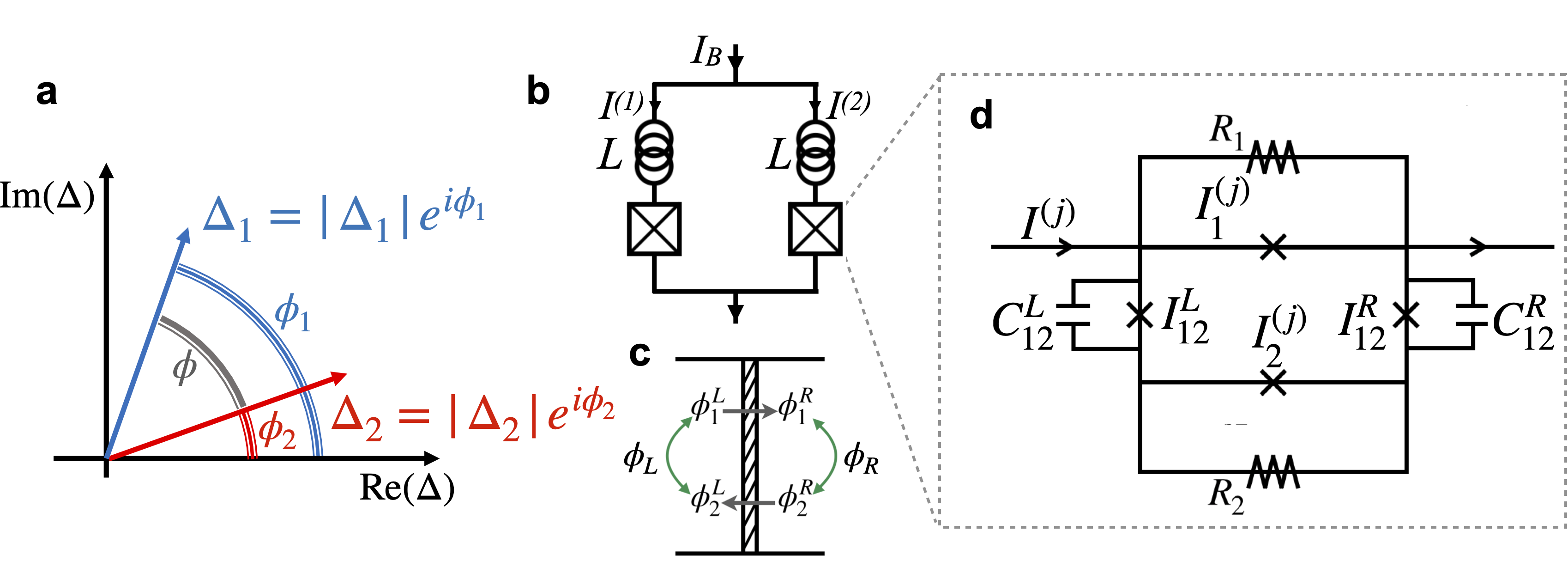
A SQUID, see Fig. 1 (b), is formed by two Josephson junctions connected in parallel and encircling a finite size area. Let be the difference between the superconducting order parameter in the right and left lead for band . We then have that the current across the JJ’s leads, for a JJ with low-medium transparency 14, is given by where is the critical supercurrent for band , and is equal to 1 for a standard JJ, and 1/2 for a topological JJ 15, 16, 17. For biased high transparency topologically trivial JJs, Landau-Zener transitions can induce a current-voltage response equivalent to a topological junction 18.
To understand the effect of a Leggett mode on the dynamics, and voltage-current (V-I) characteristic, of a JJ, we first present a simplified analysis of a voltage-biased JJ. A rigorous analysis of the realistic case of a current-biased JJ is presented later, see also the SI 19. In presence of a voltage across the JJ’s leads, the phases evolve over time according to the equations . The dynamics of the relative phase can induce oscillations in the phase difference . Let , , Fig. 1 (c), so that , where is the equilibrium value of , and the time dependent part. We can write , , with . Notice that . We consider the case when . When the Leggett mode is driven, directly or indirectly, by a periodic drive, we can assume , with the amplitude of the mode and its broadening. With this assumption we obtain , , where is an initial phase. Let’s first consider the case then and so . In this case we obtain
| (2) |
where is an integer and is the n-th Bessel function of the first kind. The d.c. current will be zero unless , in which case the current exhibits so called Shapiro spikes 20. For the experimentally more relevant case when the JJs is current biased the Shapiro spikes correspond to steps, Shapiro steps, for the d.c. voltage. If either or is equal to one we have Shapiro spikes for all integer values . If both and are equal to 1/2 Eq. (2) shows that we have Shapiro spikes only when is an even integer. In the non-ideal case, it is possible that also in this case spikes will be present for odd 21. Equation (2) shows that in general, regardless of the values of , and the phase difference , in the limit when we cannot have a suppression of the even steps alone. The reason is that when the driving a.c. term for is in phase with the driving term for .
In the limit when so that instead of Eq. (2) we obtain:
| (3) |
When , depending on the value of we can have suppression of the odd or even spikes. For we have suppression of the odd steps. In this case for the Shapiro steps’ structure is qualitatively the same as the one obtained at low frequencies and powers in the presence of a topological superconducting channel (), or Landau-Zener processes in highly transparent junctions 18. For small and non-negligible it might be difficult to pinpoint reliably the cause of the missing odd-Shapiro steps. However, for the case when we have that Eq. (3) leads to a suppression of the even Shapiro spikes, a phenomenon that cannot be attributed to the topological nature of the JJ, or Landau-Zener processes. A phase difference can be present, for example, due to strong spin-orbit coupling that causes the spin textures on the two bands to be different. In the remainder we assume .
To describe the dynamics of an a.c. current-biased 2-bands JJs we use a resistively and capacitively shunted junction (RCSJ) model 22. We assume that the external leads couple strongly to the states in band 1 and weakly to the states in band 2. This situation is realized, for instance, when placing a lead on the surface of a DSM: the states of the lead couple strongly to the DSM’s surface states and weakly to the DSM’s bulk states. In this scenario the supercurrent in the bulk band (band 2) is mediated by intraband processes. The capacitance between the two leads is very small compared to the normal resistances across the leads and so it can can be neglected. Conversely, for the inter band charge flow, within the same lead, we can neglect the resistive channel considering the non-negligible inter band capacitance . The resulting effective RCSJ model is shown in Fig. 1 (d).
In presence of the current bias , the dynamics of the RCSJ model shown in Fig. 1 (c) is described by the equations 19
| (4) | |||
| (5) |
where , , , , and . In the remainder we set , , , , and .
The dynamics of the SQUID can be obtained starting from Eqs. (4), (5) for each of the two JJs. In the remainder we will denote by the quantity for band in arm of the SQUID, see Fig. 1 (c). We assume the SQUID to be symmetric: the parameters entering the JJs’ RCSJ model, and the self inductance , are assumed to be the same for the left and right arm of the SQUID. For each band the phase difference must be equal to , where is the external flux threading the SQUID, , is an integer, , and with the total current flowing through arm . In the remainder we set . In the limit in which is small, so that , we can assume 23, with . Using Eqs. (4), (5), current conservation, and the flux quantization for , in the limit , in terms of the phases , , we find 19 that the dynamics of the SQUID is described by the equations
| (6) | |||
| (7) |
in conjunction with Eq. (5). Equation (7) shows that the SQUID’s dynamics is -periodic with respect to .
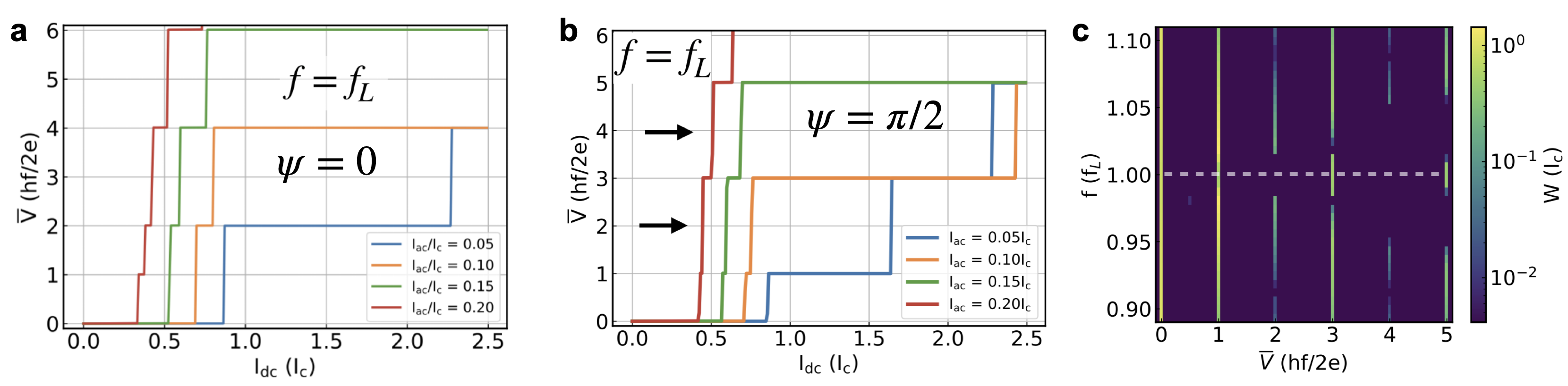
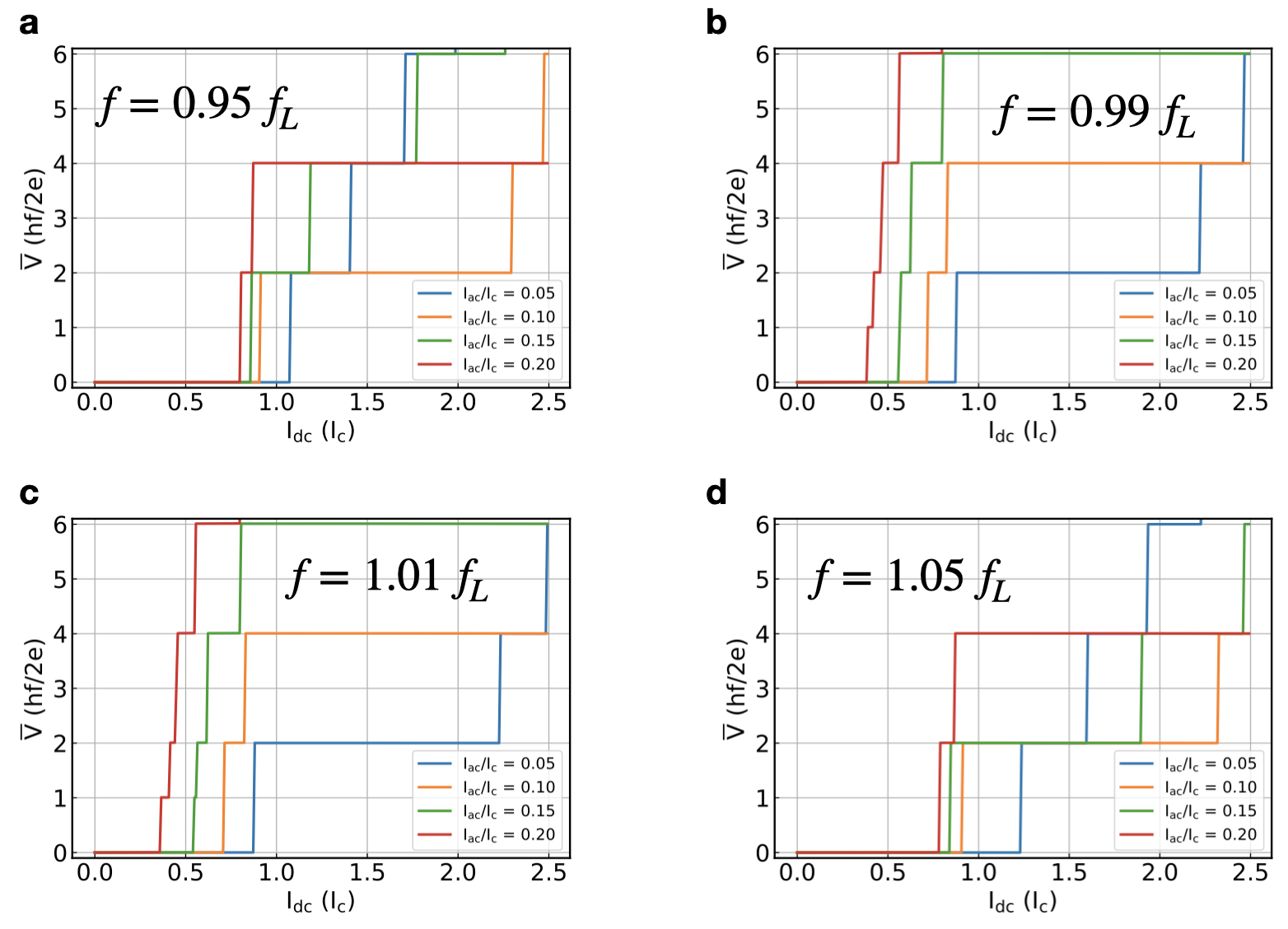
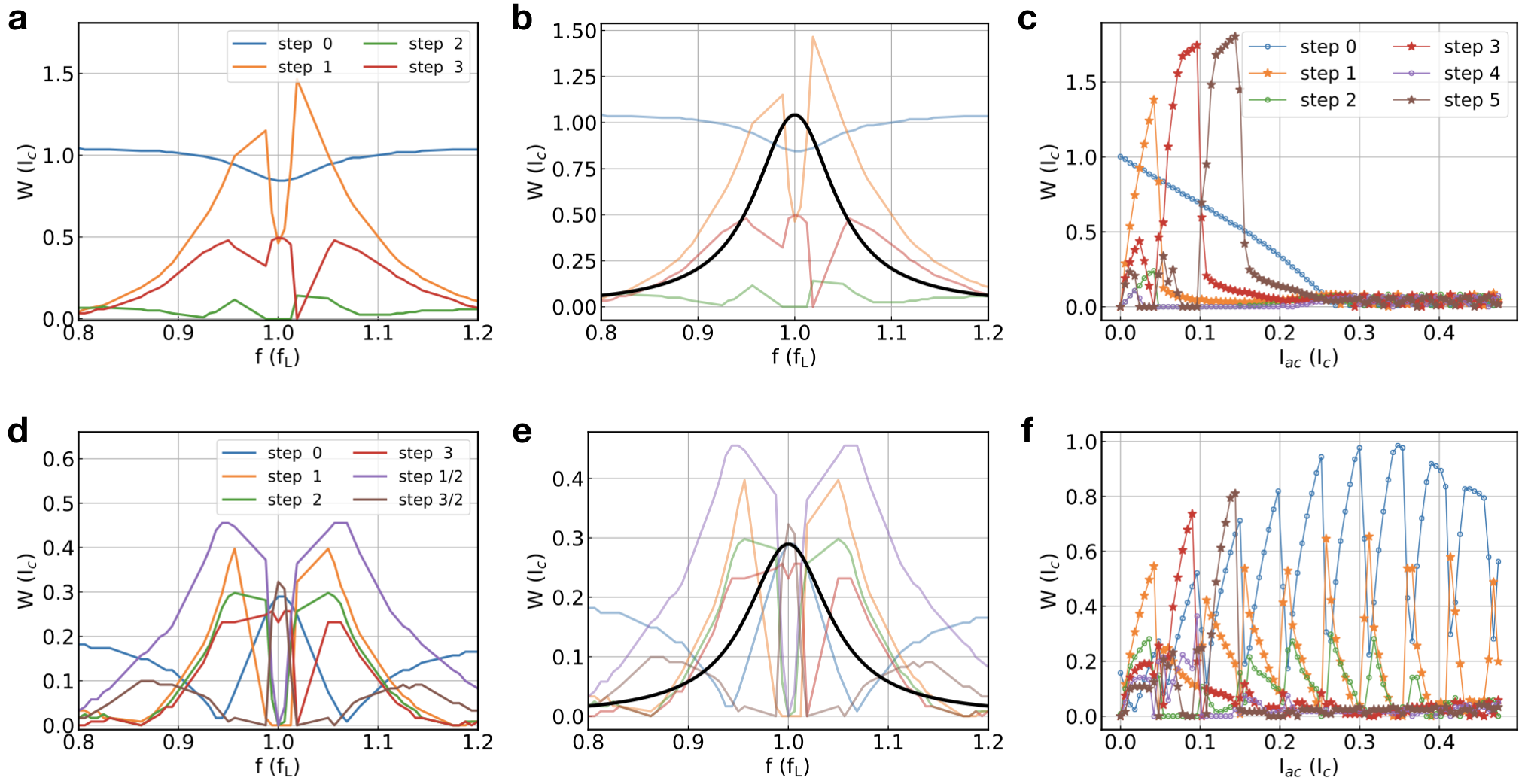
Using Eqs. (6), (7), (5) we obtain and then . Let’s first consider . For , the dependence of with respect to exhibits the standard Shapiro steps 19: all steps if either , or are equal to 1, only even steps if , 19. For , , and we have that the odd steps are strongly suppressed, see Fig. 2 (a), so that the structure of the Shapiro steps resembles the one expected for a topological JJ for which a channel with dominates. However, for , and , we have the unusual situation that only the even Shapiro steps are suppressed, as shown in Fig. 2 (b). This behavior is present as long as is within the inverse lifetime, , of the Leggett mode frequency . When we can expect to be quite small. Figure 2 (c) shows the width of the steps, , as a function of and ac frequency assuming . We see that for the even steps are suppressed while the odd steps are strong, and that for far from the resonance we recover a voltage-current profile in which all the steps are present (apart from small corrections due to higher harmonics).
We can investigate the effect of the Leggett mode on the Shapiro steps when the SQUID is threaded by a nonzero magnetic flux . For the case when , we first note that for the second term vanishes. In this case we find that the SQUID V-I curve exhibits the same Shapiro steps as for the case . When is a half-integer of the first term on the r.h.s. of Eq. (7) vanishes and the term proportional to affects the dynamics of the SQUID. In this case, when , the factor of 2 in the argument of the sine causes the appearance of half-integer Shapiro steps, as in standard SQUIDs 24, when , and the appearance of the odd Shapiro steps when .
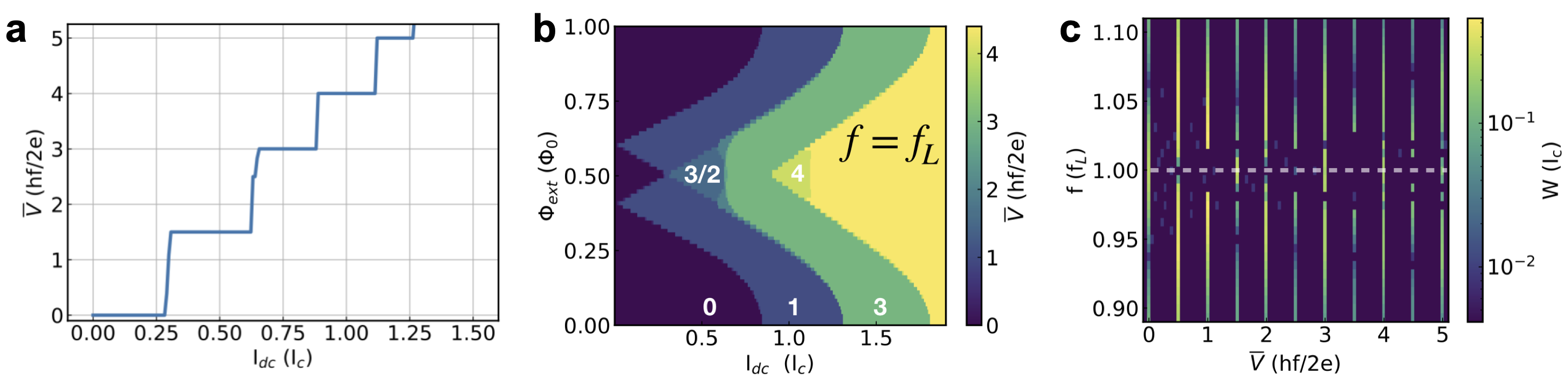
When so that is not negligible, and is not a multiple of , the SQUID’s V-I features are difficult to predict from a simple analysis of the equations. Numerically, for the case when , , and we find that the SQUID has a fairly unique V-I curve, as shown in Fig. 3. Contrary to the case of a single JJ the odd step at is absent, and a new fractional step at appears together with a step at , while the step at survives. Figure 3 (b) shows the range of values of around for which these step structure is present, and Fig. 3 (c) shows how the step structure and the width of the steps depend on the a.c. frequency , for , when .
The discussion above shows that when the equilibrium phase difference, , between the two superconducting order parameters is 0 mod , the microwave response of a SQUID in which an undamped Leggett mode is present, for is similar to one obtained when the single JJs forming the SQUID have a current phase relation that is periodic, either due to the presence of a topological superconducting channel, or Landau-Zener processes. At the same, the analysis shows that when the SQUID’s microwave response, both in the absence and presence of an external magnetic flux , exhibit unique qualitative features that cannot be attributed to topological superconducting pairing or Landau-Zener processes.
In a Dirac semimetal (DSM) the bulk 3D conduction and valence electronic bands touch at isolated points, and a projection of the spectral density onto a surface BZ reveals Fermi arcs connecting the bulk Dirac points 25, 26. DSM’s with proximity-induced superconductivity are predicted to be able to realize exotic non-Abelian anyons that can used to develop topologically-protected qubits 27 and can be used in microwave single-photon detection for sensing applications 28, 29, 30. Another aspect DSMs that has received less attention in the literature concerns the multiband properties of superconducting DSMs 31, 32. By placing a superconducting material on the surface of the Dirac semimetal superconducting pairing can be induced in 32. The pairing has been shown to be characterized by two order parameters, , . In addition, recent experiments on single JJs formed by superconducting leads based on Al/ have shown compelling signatures that at equilibrium the phase difference, , between the two phases across the junction arising from the two superconducting order parameters is equal to , implying 33. Motivated by these results and the theoretical analysis above we have investigated the microwave response of a SQUID based on Al/. Details about the fabrication and measurement of the device can be found in the Methods section and SI 19.
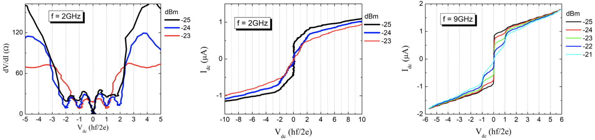
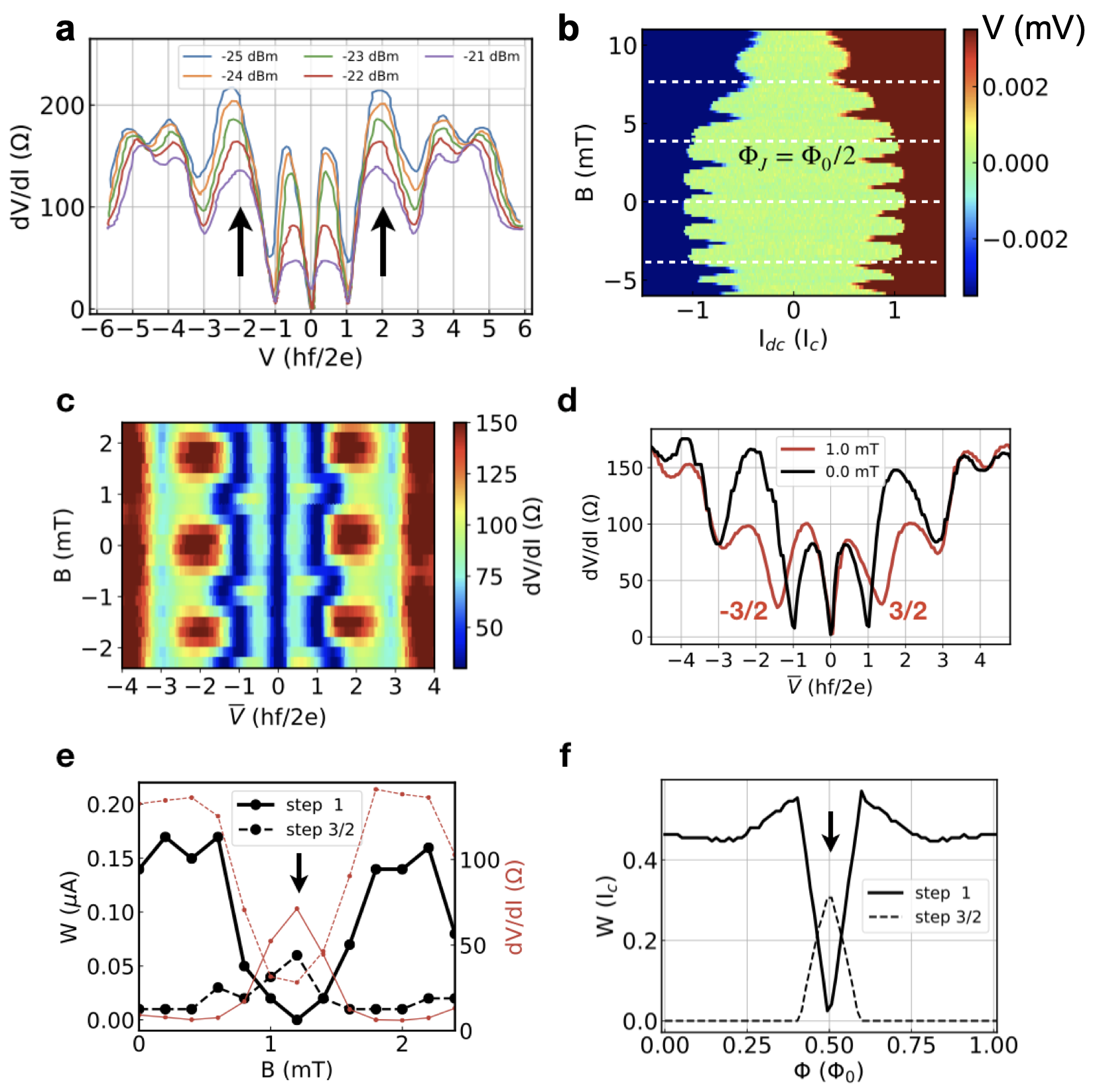
At low frequencies, GHz, and , the SQUID’s measured exhibits peaks and valleys consistent with the standard Shapiro steps’ structure (see SI 19). However, for GHz, for all the microwave powers values considered, the first and third steps are clearly visible but the second step is strongly suppressed, see Fig. 3 (a). Considering that our device shows no hysteretic features in the current-voltage characteristic 19, and no evidence of a bias-dependent normal resistance, mechanisms for missing Shapiro steps due to hysterisis 34 or bias-dependent resistance 35 are not relevant. Based on the analysis above, we therefore conclude that the results shown in Fig. 3 (a) can only be explained by considering the presence of a Leggett mode with GHz, and .
Figure 4 (b) shows the voltage across the SQUID as a function of the perpendicular magnetic field in the d.c. limit, . SQUID oscillations of periodicity 1.8 mT are observed, which correspond to an effective SQUID ring area of 1.14 m2. Enveloping the SQUID oscillations is the Fraunhofer diffraction pattern of the JJs. For such that anomalous oscillations can also be observed. The presence of these oscillations is consistent with a -periodic supercurrent in each of the JJs forming the SQUID due the fact that .
In Fig. 4 (c) we present as a color plot the measured as a function of and in the presence of an a.c. component of the current with GHz, and relative power -22 dB. In addition, to the periodicity of the Shapiro steps with respect to B, with period consistent with the periodicity observed in the d.c. limit, Fig. 4 (b), we observe interesting features for mT corresponding to . To more clearly identify these features, in Fig. 4 (d) we show the traces for and mT. We see that for mT, i.e., , both the first and second Shapiro steps are suppressed and a 3/2 subharmonic step emerge, features that are remarkably consistent with the theoretical results shown in Fig. 3. To better understand the evolution of the Shapiro steps’ structure with when GHz, in Fig. 4 (e) we plot the measured width of the steps at and as a function of . We see that when mT, , the width of the first step is suppressed whereas the width of the 3/2 step is enhanced around mT. The evolution of the 1 and 3/2 steps with is in good qualitative agreement with the theoretical results, shown in Fig. 4 (f).
In conclusion, we have presented a theoretical analysis of the response of a SQUID to microwave radiation in the presence of a Leggett mode, using an effective resistively and capacitively shunted junction model for Josephson junctions formed by superconducting leads with two order parameters. We have shown that, when the a.c. current’s frequency is close to the frequency of the Leggett mode, the dc current-voltage characteristics of both a single junction and a SQUID exhibit suppressed odd Shapiro steps if the equilibrium relative phase, , between the phases of the two superconducting order parameters is zero, and strongly suppressed even Shapiro steps if . In the absence of hysteretic effects and spurious cavity resonances, the suppression of only the even-steps cannot be explained using other mechanisms, such as the presence of channels for the JJs with a -periodic current phase relation. In addition, we have shown that for , and , the evolution of a SQUID’s Shapiro steps structure with the magnetic flux possess unique qualitative features. We have then presented experimental measurements taken on a SQUID formed by Josephson junctions whose superconducting leads are formed by Al placed on top of the Dirac semimetal . The results presented are consistent with Al inducing a two-band superconducting pairing in , with a difference between the phases of the two superconducting order parameters, and the presence of a Leggett mode with GHz.
The theoretical and experimental results presented show that the SQUIDs’ response to microwave radiation can be used to identify unambigously the presence of Leggett modes, especially when the equilibrium phase difference between the phases of the superconducting order parameters is not zero. In addition, the results strongly suggest that in a Dirac semimetal like the multi-band superconducting state induced via proximity effect exhibits an undamped Leggett mode. In this study, we used Cd3As2 as an exemplar Dirac Semimetal, but our results indicate that underdamped Leggett modes may be present also in other superconducting Dirac semimetals.
Methods
Fabrication. Mechanical exfoliation is used to obtain flat and shiny Cd3As2 thin flakes of thickness 200 nm from an initial bulk ingot material 30, synthesized via a chemical vapor deposition method36. The SQUID structure is fabricated by first depositing the Cd3As2 thin flake on a Si/SiO2 substrate with a 1 m thick SiO2 layer. Next, e-beam lithography is used to define 300 nm thick Al electrodes. Additional details about the device can be found elsewhere 33.
Measurements. To measure the sample resistance, a 11 Hz phase-sensistive lock-in amplifier technique is used with an excitation current of 10 nA. To measure the differential resistance, a large direct current up to 2 A is added to the ac current. The entire device is emmersed in a cryogenic liquid at a temperature of 0.25 K, well below the devices superconducting transition temperature. To measure the microwave response of the device, an Agilent 83592B sweep generator is used to generate microwaves, which are conducted through a semirigid coax cable.
Simulations. The numerical integration of the dynamical equations have been performed using the adaptive Runge-Kutta of order 4 and 5.
Data availability
The data that support the findings of this study are available within the paper and its Supplementary Information.
All the codes used to obtain the numerical results presented are available upon request.
References
- Tsuda et al. 2001 S. Tsuda, T. Yokoya, T. Kiss, Y. Takano, K. Togano, H. Kito, H. Ihara, and S. Shin, Evidence for a multiple superconducting gap in from high-resolution photoemission spectroscopy, Phys. Rev. Lett. 87, 177006 (2001).
- Souma et al. 2003 S. Souma, Y. Machida, T. Sato, T. Takahashi, H. Matsui, S.-C. Wang, H. Ding, A. Kaminski, J. C. Campuzano, S. Sasaki, and K. Kadowaki, The origin of multiple superconducting gaps in , Nature 423, 65 (2003).
- Stewart 2011 G. R. Stewart, Superconductivity in iron compounds, Reviews of Modern Physics 83, 1589 (2011).
- Ugeda et al. 2015 M. M. Ugeda, A. J. Bradley, Y. Zhang, S. Onishi, Y. Chen, W. Ruan, C. Ojeda-Aristizabal, H. Ryu, M. T. Edmonds, H.-Z. Z. et al. Tsai, A. Riss, S. K. Mo, D. Lee, A. Zettl, Z. Hussain, Z. X. Shen, and M. F. Crommie, Characterization of collective ground states in single-layer NbSe 2, Nature Physics 12, 92 (2015).
- Xi et al. 2016 X. Xi, Z. Wang, W. Zhao, J. H. Park, K. T. Law, H. Berger, L. Forró, J. Shan, and K. F. Mak, Ising pairing in superconducting NbSe2 atomic layers, Nature Physics 12, 139 (2016).
- Leggett 1966 A. J. Leggett, Number-phase fluctuations in two-band superconductors, Progress of Theoretical Physics 36, 901 (1966).
- Brinkman et al. 2006 A. Brinkman, S. van der Ploeg, A. Golubov, H. Rogalla, T. Kim, and J. Moodera, Charge transport in normal metal–magnesiumdiboride junctions, Journal of Physics and Chemistry of Solids 67, 407 (2006), spectroscopies in Novel Superconductors 2004.
- Blumberg et al. 2007 G. Blumberg, A. Mialitsin, B. S. Dennis, M. V. Klein, N. D. Zhigadlo, and J. Karpinski, Observation of leggett’s collective mode in a multiband superconductor, Phys. Rev. Lett. 99, 227002 (2007).
- Klein 2010 M. V. Klein, Theory of raman scattering from leggett’s collective mode in a multiband superconductor: Application to , Phys. Rev. B 82, 014507 (2010).
- Mou et al. 2015 D. Mou, R. Jiang, V. Taufour, R. Flint, S. L. Bud’ko, P. C. Canfield, J. S. Wen, Z. J. Xu, G. Gu, and A. Kaminski, Strong interaction between electrons and collective excitations in the multiband superconductor , Phys. Rev. B 91, 140502 (2015).
- Giorgianni et al. 2019 F. Giorgianni, T. Cea, C. Vicario, C. P. Hauri, W. K. Withanage, X. Xi, and L. Benfatto, Leggett mode controlled by light pulses, Nature Physics 15, 341 (2019).
- Zhao et al. 2020 S. Z. Zhao, H.-Y. Song, L. L. Hu, T. Xie, C. Liu, H. Q. Luo, C.-Y. Jiang, X. Zhang, X. C. Nie, J.-Q. Meng, Y.-X. Duan, S.-B. Liu, H.-Y. Xie, and H. Y. Liu, Observation of soft leggett mode in superconducting , Phys. Rev. B 102, 144519 (2020).
- Ota et al. 2009 Y. Ota, M. Machida, T. Koyama, and H. Matsumoto, Theory of Heterotic Superconductor-Insulator-Superconductor Josephson Junctions between Single- and Multiple-Gap Superconductors, Physical Review Letters 102, 237003 (2009).
- Beenakker 1992 C. W. J. Beenakker, Three “Universal” Mesoscopic Josephson Effects (1992) pp. 235–253.
- Fu and Kane 2009 L. Fu and C. L. Kane, Josephson current and noise at a superconductor/quantum-spin-Hall-insulator/superconductor junction, Physical Review B 79, 161408 (2009).
- Wiedenmann et al. 2016 J. Wiedenmann, E. Bocquillon, R. S. Deacon, S. Hartinger, O. Herrmann, T. M. Klapwijk, L. Maier, C. Ames, C. Brüne, C. Gould, A. Oiwa, K. Ishibashi, S. Tarucha, H. Buhmann, and L. W. Molenkamp, 4-periodic Josephson supercurrent in HgTe-based topological Josephson junctions, Nature Communications 7, 10303 (2016).
- Dartiailh et al. 2021a M. C. Dartiailh, W. Mayer, J. Yuan, K. S. Wickramasinghe, A. Matos-Abiague, I. Žutić, and J. Shabani, Phase Signature of Topological Transition in Josephson Junctions, Physical Review Letters 126, 036802 (2021a).
- Dartiailh et al. 2021b M. C. Dartiailh, J. J. Cuozzo, B. H. Elfeky, W. Mayer, J. Yuan, K. S. Wickramasinghe, E. Rossi, and J. Shabani, Missing Shapiro steps in topologically trivial Josephson junction on InAs quantum well, Nature Communications 12, 78 (2021b).
- 19 Supplementari information .
- Shapiro 1963 S. Shapiro, Josephson currents in superconducting tunneling: The effect of microwaves and other observations, Phys. Rev. Lett. 11, 80 (1963).
- Domínguez et al. 2017 F. Domínguez, O. Kashuba, E. Bocquillon, J. Wiedenmann, R. S. Deacon, T. M. Klapwijk, G. Platero, L. W. Molenkamp, B. Trauzettel, and E. M. Hankiewicz, Josephson junction dynamics in the presence of 2 and 4 -periodic supercurrents, Physical Review B 95, 195430 (2017).
- Barone and Paterno’ 1982 A. Barone and G. Paterno’, Physics and Applications of the Josephson Effect (1982).
- Romeo and De Luca 2005 F. Romeo and R. De Luca, Shapiro steps in symmetric -SQUID’s, Physica C: Superconductivity 421, 35 (2005).
- Vanneste et al. 1988 C. Vanneste, C. C. Chi, W. J. Gallagher, A. W. Kleinsasser, S. I. Raider, and R. L. Sandstrom, Shapiro steps on current-voltage curves of dc SQUIDs, Journal of Applied Physics 64, 242 (1988).
- Wehling et al. 2014 T. Wehling, A. Black-Schaffer, and A. Balatsky, Dirac materials, Advances in Physics 63, 1 (2014).
- Armitage et al. 2018 N. P. Armitage, E. J. Mele, and A. Vishwanath, Weyl and Dirac semimetals in three-dimensional solids, Reviews of Modern Physics 90, 015001 (2018).
- Kitaev 2001 A. Y. Kitaev, Unpaired majorana fermions in quantum wires, Physics-Uspekhi 44, 131 (2001).
- Chi et al. 2020 F. Chi, T.-Y. He, J. Wang, Z.-G. Fu, L.-M. Liu, P. Liu, and P. Zhang, Photon-assisted transport through a quantum dot side-coupled to majorana bound states, Frontiers in Physics 8, 254 (2020).
- Chatterjee et al. 2021 E. Chatterjee, W. Pan, and D. Soh, Microwave photon number resolving detector using the topological surface state of superconducting cadmium arsenide, Phys. Rev. Research 3, 023046 (2021).
- Pan et al. 2021 W. Pan, D. Soh, W. Yu, P. Davids, and T. M. Nenoff, Microwave response in a topological superconducting quantum interference device, Scientific Reports 11, 8615 (2021).
- Wang et al. 2018 A.-Q. Wang, C.-Z. Li, C. Li, Z.-M. Liao, A. Brinkman, and D.-P. Yu, -periodic supercurrent from surface states in nanowire-based josephson junctions, Phys. Rev. Lett. 121, 237701 (2018).
- Huang et al. 2019 C. Huang, B. T. Zhou, H. Zhang, B. Yang, R. Liu, H. Wang, Y. Wan, K. Huang, Z. Liao, E. Zhang, S. Liu, Q. Deng, Y. Chen, X. Han, J. Zou, X. Lin, Z. Han, Y. Wang, K. T. Law, and F. Xiu, Proximity-induced surface superconductivity in Dirac semimetal Cd3As2, Nature Communications 10, 2217 (2019).
- Yu et al. 2018 W. Yu, W. Pan, D. L. Medlin, M. A. Rodriguez, S. R. Lee, Z. Q. Bao, and F. Zhang, and 4 Josephson Effects Mediated by a Dirac Semimetal, Physical Review Letters 10.1103/PhysRevLett.120.177704 (2018).
- Shelly et al. 2020 C. D. Shelly, P. See, I. Rungger, and J. M. Williams, Existence of shapiro steps in the dissipative regime in superconducting weak links, Phys. Rev. Applied 13, 024070 (2020).
- Mudi and Frolov 2021 S. R. Mudi and S. M. Frolov, Model for missing shapiro steps due to bias-dependent resistance (2021).
- Ali et al. 2014 M. N. Ali, Q. Gibson, S. Jeon, B. B. Zhou, A. Yazdani, and R. J. Cava, The crystal and electronic structures of cd3as2, the three-dimensional electronic analogue of graphene, Inorganic Chemistry 53, 4062 (2014), pMID: 24679042, https://doi.org/10.1021/ic403163d .
Acknowledgements
J.J.C, W.P., and E.R. acknowledge support from DOE, Grant No DE-SC0022245. J.J.C. also acknowledges support from the Graduate Research Fellowship awarded by the Virginia Space Grant Consortium (VSGC). The authors acknowledge the material synthesis work of David X. Rademacher. The work at Sandia is supported by a LDRD project. Device fabrication was performed at the Center for Integrated Nanotechnologies, a U.S. DOE, Office of BES, user facility. Sandia National Laboratories is a multimission laboratory managed and operated by National Technology and Engineering Solutions of Sandia LLC, a wholly owned subsidiary of Honeywell International Inc. for the U.S. DOE’s National Nuclear Security Administration under contract DE-NA0003525. This paper describes objective technical results and analysis. Any subjective views or opinions that might be expressed in the paper do not necessarily represent the views of the U.S. DOE or the United States Government.
Authors contributions
J.J.C. and E.R. developed the theoretical model. J.J.C. carried out the numerical simulations. W.Y., P.D., T.M.N., D.B.S., and W.P. conceived the experiment, and contributed to material growth, device fabrication, electronic transport measurements, and experimental data analysis. W.P. coordinated the experiment. All authors contributed to interpreting the data. The manuscript was written by J.J.C., W.P., and E.R. with suggestions from all other authors.
SUPPLEMENTAL MATERIAL
I Dynamics of a two-bands Josephson junction in the presence of a Leggett mode
Let’s consider a Josephson junction (JJ) where each of the superconducting electrodes are two-band superconductors with phases . Let the intraband phase differences across the junction be . To describe the interband dynamics in the JJ, we consider the resistively and capacitively shunted junction (RCSJ) model shown in Fig. 1 (d). For the ac Josephson effect we have that the voltage across a weak link, denoted by crosses in Fig. 1 (d), is given by , where is the phase difference across the weak link of the superconducting order parameters. Let , and . From Kirchhoff’s voltage law applied to the loop formed by the weak links in Fig. 1 (d) we obtain
| (S1) |
and then .
Let , be the interband critical dc Josephson current on the left side and right side, respectively, of the circuit shown in Fig. 1 (d) of the main text, and , the left-side, right-side, interband capacitances. From charge conservation we obtain
| (S2) | |||
| (S3) |
If we assume and , it is clear that . Then, from Eq. (S1) we obtain
| (S4) |
Equation (S4) establishes the direct relation between phases across the Josephson junction, , and the phases , , characterizing the Leggett modes in the two superconducting leads. In particular Eq. (S4) implies that the dynamics of the Leggett modes will in general affect the dynamics of the phases across the JJ.
We now obtain the dynamics of the current biased JJ shown in Fig. 1 (d) taking into account the presence of a Leggett mode. When a bias current is applied across the junction, charge conservation gives
| (S5) |
where is the critical Josephson current for the band and is the current through the resistive channel in the band. Let . Considering Eq. (S4), we can write , and then
| (S6) |
where is the parallel resistance of the resistors and , quantifies the asymmetry in resistance between the bands. Defining , , we can write Eq. (S6) as
| (S7) |
where currents have been normalized with respect to : and . Equation (S7) is the key equation to describe the behavior of the 2-band JJ, and SQUID (see next section), in the presence of a Leggett mode. The key modification due to the Leggett mode is the term . The evolution in time of depends on several microscopic details that are beyond the level of the effective description used here. We have assumed to follow the dynamics of a harmonic oscillator driven by a periodic term due to the microwave radiation. Below we show that, in first approximation, this simplified evolution is also consistent with the RSCJ model shown in Fig. 1 (d).
We can rewrite Eq. (S3) in the form:
| (S8) |
where , is the Leggett mode’s frequency, and Equations (S7) and (S8) completely define the dynamics of the two-bands JJ described by the effective RCJS circuit shown in Fig. 1 (d). Eq. (S8) is equivalent to the equation for a damped, driven, oscillator; the right hand side of the equation being the driving term. To qualitatively understand the effect of a resonant Leggett mode, in first approximation, we can neglect the damping term proportional , and the term on the right hand side of the equation. Then by linearizing the around the equilibrium value for we obtain the simple equation
| (S9) |
describing a harmonic oscillator periodically driven by a force of amplitude , with . Here . In our calculations the effect of the damping term is taken into account by considering a finite broadening, , of the Leggett mode’s resonance frequency.
II Dynamics of a SQUID formed by two-bands superconducting leads and in the presence of a Leggett mode.
In this section we derive the equations that we use to simulate the dynamics of a two-bands SQUID in presence of a resonant Leggett mode. We assume the SQUID to be symmetric:
where denotes quantity in band , and arm of the SQUID. Normalizing as usual the currents with , from charge conservation and magnetic flux quantization we have:
| (S10) | |||
| (S11) |
where , , and is an integer that without loss of generality we can set equal to zero. For the total current in arm we have:
| (S12) |
Let’s now define
| (S13) |
Because the flux quantization condition is the same for both bands, we have , and . is the phase associated to the Leggett mode and its dynamics is given by Eq. (S9). By using Eq. (S12) to express in Eqs. (S10), (S11) we obtain the following dynamical equations for and
| (S14) | |||
| (S15) |
where
| (S16) | ||||
| (S17) |
is the supercurrent fraction of the total current across the SQUID. In the limit we can assume 23
| (S18) |
From Eq. (S15), for , we find:
| (S19) |
Replacing in the equation (S16) for the expression for obtained by combining Eqs. (S18), (S19), we obtain, to linear order in :
| (S20) |
Notice that up to linear order in only depends on and .
Equations (S14), (S20), and (S9) completely determine the dynamics of the SQUID. To numerically integrate these non-linear differential equations we used an adaptive fourth-order Runge-Kutta method. The parameters of the model used in the simulations are given in Table 1.
| 0.005 | -0.6 | 1.5 |
III Additional theoretical results
In Fig. S1 we present additional numerical VI curves in the case where . Here, we see, as mentioned in the main text, the missing steps are odd integer multiples of . The ac frequency range in Fig. S1a-d is chosen to cover the approximate half-width of the Leggett mode resonance in the amplitude , illustrating the robustness of the missing steps over a bandwidth proportional to the inverse lifetime of the Leggett mode.
In Fig. S2, we present calculations of Shapiro step widths of the step corresponding to in the case where . Fig. S2a-b show the step width ac frequency dependence near the Leggett mode frequency and for and , where a normalized is shown in black for reference. Clearly, deviations from the conventional Shapiro step dependence follows the resonant Leggett amplitude. Fig. S2c show the power dependence of steps for and . We see the gap is suppressed at , which is much smaller than expected in the conventional case. Furthermore, the step width dependence of odd steps exhibit resonant features appearing consecutively with increasing power and disappering with the gap closure. Once the gap is closed, step widths exhibit oscillations in power, similar to the conventional Bessel regime.
In Fig. S2d-e, we show the step width ac frequency dependence near the Leggett mode frequency and for and , where a normalized is shown in black for reference. We observe a weakening of the gap near the Leggett frequency, similar to the zero-flux case, but the gap actually becomes enhanced at the Leggett frequency. In Fig. S2f, we present the power dependence of steps for and . We find similar resonant behavior of odd steps at low power, but the features are difficult to distinguish between oscillations at higher powers associated with the typical Bessel oscillations.
IV Device characterization
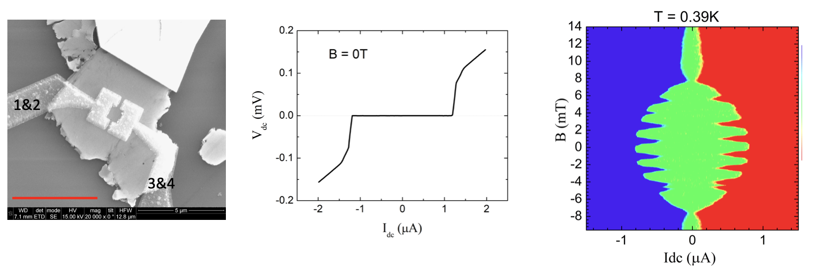
Fig. S3a shows an SEM image of the SQUID device used in the experiment. The scale bar is 5 m. For each Josephson junction in the SQUID, the width is 600 nm, and the gap 150 nm. The size of the middle open square is about 800nm x 800nm. For IV and differential resistance measurements, the ac/dc current runs from contact 1 to contact 3. The dc/ac voltage is measured between contacts 2 and 4. In Fig. S3b, we present the I-V curve measured at B = 0T. The critical current is . In Fig. S3c, we show I-V curves as a function of out-of-plane magnetic fields, at a higher temperature of T = 0.39K (compared to Fig. 4a in the main text). In this plot, red color represents positive Vdc, blue negative Vdc. In the green color regime, Vdc = 0. A typical feature, i.e., the envelop of the SQUID oscillatory pattern being modulated by the Fraunhofer diffraction pattern of the single Josephson junction, is clearly seen.
V Additional experimental results
In Fig. S4 we present additional measurements of and VI curves at zero magnetic field. In Fig. S4a, we show the differential resistance at 2 GHz for various microwave powers. We see that steps are clearly observed before dissipative effects wash out higher steps. The measured VI curves are shown in Fig. S4b, where the steps are not easily resolved with the naked eye (hence, the need for measurements). Fig. S4c shows VI curves at 9 GHz, showing a large first steps, the clear suppression of the second step, and a weak third step.