Controller design and experimental evaluation of a motorised assistance for a patient transfer floor lift
Abstract
Patient transfer is a critical task in patient care and medical sectors. However, it is challenging because it exposes caregivers to injury risks. Available transfer devices, like floor lifts, lead to improvements but are far from perfect. They do not eliminate the caregivers’ risk for musculoskeletal disorders, and they can be burdensome to use due to their poor manoeuvrability. This paper presents a new motorised floor lift with a single central motorised wheel connected to an instrumented handle. It proposes admittance controllers — the reference velocity of the motorised wheel, is computed as a function of the force applied on the handle — 1) to achieve the best manoeuvrability, 2) to reduce the effort required in a task, decreasing the risk of injuries among caregivers , 3) while guaranteeing the security and comfort of patients. Two controller designs, one with a linear admittance law and a non-linear admittance law with variable damping, were developed and implemented on a prototype. Tests were performed on seven participants to evaluate the performance of the assistance system and the controllers. The experimental results show that 1) the motorised assistance with the variable damping controller improves manoeuvrability by 28%, 2) reduces the amount of effort required to push the lift by 66% and 3) provides the same level of patient comfort compared to a standard unassisted floor lift.
Index Terms:
Floor lift, human robot interaction, admittance controller, variable admittance.I INTRODUCTION
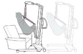
The ageing population and the worldwide increase in body weight have caused new issues in the medical and paramedical sectors. The caregiver profession is associated with many musculoskeletal disorders due to the considerable amount of effort required in a workday [1], which is amplified by the population’s increase in weight. The transfer of a passive patient, one who is unable to move independently from one place to another, is one of the most redundant and difficult tasks for caregivers and is partly responsible for their back disorders [2]. The National Institute for Occupational Safety and Health (NIOSH) conducted different studies to better understand the development of back disorders. The spinal column has a safety limit of 3,400 N in compression and 1,000 N in shear [3]; they are often exceeded during patient-handling tasks [4]. To relieve the caregivers, hospitals and retirement houses are equipped with assistance devices, such as the floor lifts (Figure. 1).
Although these devices have many advantages over unassisted methods in terms of transferring patients, they do not perfectly protect the spinal column. Some medical experiments were performed to measure the effort some users put on their spinal column during a transfer using a floor lift, and it has been observed that the NIOSH’s limits were still exceeded [5].
To reduce the amount of effort required for a transfer, it was proposed to motorise the floor lift, as has been done for Joy in Care’s TouchMove [6] or Handicare’s EvaDrive [7]. The integration of robotics in other medical devices, such as beds or wheelchairs, has already proven to be successful [8], because it has decreased the amount of effort required to push these devices, thus improving their ease of use. Ideally, a good control strategy must reduce the needed amount of effort efficiently, guarantee security and comfort for the patient being carried and preserve the user’s manoeuvrability. Most of the control strategies developed to assist an operator in similar tasks focus only on one of these three aspects. Solea et al. proposed a control strategy centred on the comfort of the person in a motorised wheelchair [9]. Duchaine et al. recommended a strategy in which the user’s manoeuvrability and control are improved through a variable controller [10]. Rosen et al. based their control strategy on myosignals to reduce the required effort for a task [11]. Guo et al. presented an admittance control to command a motorised bed, which improves manoeuvrability and reduces the effort required to move the bed, but no comparison is made with other control strategies to get the best way to control the robotic bed [8]. Finally, many articles focus only on the ergonomic aspect of the use of the lift, not on the integration of motorised assistance [12].
The main contributions of this article are the development of a controller for motorised assistance of a fifth wheel and an extensive experimental evaluation of the assistance system’s performance in the context of three aspects: 1) manoeuvrability of the lift, 2) reduction of effort and 3) comfort of the patient.
II REQUIREMENTS
The design of the motorised assistance controller is driven by three main performance aspects: effort, manoeuvrability and comfort.
II-A Effort
One important performance goal is to minimise the effort required to push the lift. The ISO 10535:2006 standard [13] imposes a maximum starting force of 160 N and a maximum driving force of 65 N. Moreover, to protect the spinal column, there should be no more than 3,400 N in compression and 1,000 N in shear, on the spinal column. In their publication, Weston et al. recommended a limit of 66.3 Nm of hand torque to avoid exceeding the spinal column’s limits when pushing a wheelchair [14].
II-B Patient’s Comfort
During a transfer, the control strategy must guarantee the comfort of the passenger, who is usually frail and often suffer from cognitive impairment. The motion of the lift must be smooth enough to keep the passenger in safe conditions. The ISO 2631-1:1997 automotive standard [15] proposes a method to determine the quality of the motion in terms of comfort (Table. I). The point is to obtain an overall root mean square (rms) acceleration in the range of “not uncomfortable” to “extremely uncomfortable.” The overall rms acceleration is defined as follows:
| (1) |
where , and are the rms accelerations along the x, y and z axes, respectively, and , and are multiplying factors. For a seated person, and . The goal for the lift is to have the overall acceleration under (see Table I).
| Overall action | Consequence |
|---|---|
| Not uncomfortable | |
| A little uncomfortable | |
| Fairly uncomfortable | |
| Uncomfortable | |
| Very uncomfortable | |
| Extremely uncomfortable |
II-C Manoeuvrability
The user’s manoeuvrability is one of the most important criteria for the performance of the lift, and it can impact the two previous criteria. If the user does not have the full control of the motorised lift, the amount of effort will increase a lot. It will affect the overall acceleration, and the two criteria will be spoiled. Unfortunately, no standard gives any indications about how to evaluate manoeuvrability, unlike the two previous aspects. Duchaine et al. counted the number of overshoots when a user makes a predefined path to compare the manoeuvrability from one controller to another [10]. In the same way, Guo et al. counted the number of collisions and the time taken to perform a transfer [8]. In this study, manoeuvrability will be quantified with two criteria: 1) the number of collisions and 2) the time required to perform a transfer.
III SYSTEM AND MODELISATION
III-A The Fifth Wheel Concept
This study will be based on the motorised fifth wheel concept. It consists in adding a fifth uniaxial motorised wheel to a basic floor lift with four swivelling wheels. These motorised wheels provide power to assist users while they are pushing forward or backward the lift. A wheel is linked to a load cell fixed on the handle of the lift to measure the user’s intentions. The fifth wheel also has a passive function. It offers a judiciously placed pivot point that allows the user to turn the lift easily when it is transferring a patient. Even if the wheel cannot provide torque to rotate the lift, the user will benefit from a lever-arm effect due to the pivot point created by the fifth wheel, as demonstrated in section VI-A, by the experimental results.
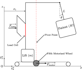
III-B Dynamic Model
To study the behaviour of this concept, a simple longitudinal dynamic model is proposed (Figure 2). It is composed of a first mass (m) representing the floor lift moving in linear motion and a second suspended mass (M) representing the patient balancing motions in the sling (Figure 1). This system is submitted to the motorised wheel’s and the user’s efforts. Some external perturbations can influence the behaviour of the system, such as dry or viscous friction. Some detailed values can be found in Table II. Floor lifts are designed to transfer people up to 272 kg. Thus, different weights of patients are taken into consideration to design the controller.
| Requirement | Value |
|---|---|
| Maximal speed | 0.8 |
| Patient weight (M) | [0-272] kg |
| Lift weight (m) | 100 kg |
| Length of the pendulum (L) | 0.5 m |
Based on this model, the differential equations are implemented through a computer simulation to evaluate the performances.
| (2) |
IV Controller Design
IV-A Global controller architecture
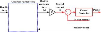


Three main families of control architectures are possible, with different types of low-level wheel inner loops (Figure 3). A current controller (in red Figure 3) is used to control the tension () sent to the motor to get to the desired current (). The desired current is determined by an outer loop with different control architecture options (Figures 3(b), 3(d) and 3(c))
The first option (Figure 3(b)), is a friction compensation controller, which estimates the resistive force at the wheel using a velocity measurement and compensates it with the motorised wheel [16]. This approach has the advantage of allowing the user to push on the system at any contact point since the user force measurement is not required. However, the approach has drawbacks and risk issues to which the floor-lift application is particularly sensitive. The variety of external conditions, such as the floor type (carpet, concrete, parquet) or the weight of the patient makes it difficult to precisely estimate the resistive force at the wheel. Furthermore, with aggressive compensations of the friction force, there is a risk of overestimating the friction that could lead to system instability.
The second option (Figure 3(c)), is a force amplification scheme. Leveraging an instrumented handle, the user’s force is measured and filtered in real time. The motor is asked to provide assistance force () proportional to the user’s force.
The third option (Figure 3(d)), is an admittance control scheme that uses both sensors (wheel velocity and user’s force). A velocity controller is used at low levels to impose a wheel motion. The desired wheel velocity is computed by an outer loop that consists of a virtual dynamic model (mass damper) which input is the user force at the handle.
Option 1 was quickly set aside for this particular application since the risk of instability would be unacceptable in the context of transporting patients. Options 2 and 3 were evaluated in more details since they both have their advantages and their drawbacks for this application. The force amplification scheme directly converts the force of the user into torque on the wheel. The user force straightly affects the lift motion, resulting in better manoeuvrability. Also, with this option, the lift remains backdrivable if a user tries to move it without using the handle. With an admittance control, the user’s force is converted into speed through software. The wheel motion is imposed by the controller, which determines the torque of the wheel. This can be less intuitive to use since the link between the user and the motion is more indirect.
However, with this approach, the behaviour is much less sensitive to a change in the weight of the patient or a change in friction due to different floor conditions (linoleum, concrete, tile, carpet, etc.). For a given input force of the user, the same final speed will be reached regardless of the external conditions. With the force amplification scheme, the final speed will depend on the friction conditions and the weight of the patient.
A simulation of the lift’s behaviour with two scenarios was performed to assess the difference in sensibility between control options 2 and 3. The first scenario is with a patient of 90 kg and a small viscous damping coefficient (50 Ns/m similar to a concrete floor). The second one is with a patient at 272 kg and a high damping coefficient (100 Ns/m similar to a carpet floor, worst case). It has been observed that the admittance controller has nearly the same behaviour regardless of the external conditions, contrary to the force amplification scheme. This difference in behaviour depends on the mass and floor conditions, has an impact on the manoeuvrability for the user. If users get used to a certain behaviour with a precise weight and then take care of ananother patient with a different weight and use the lift on a new floor (going from a bedroom to a bathroom, for instance), they will have to deal with a new comportment of the lift. Because the user is not expecting to face this new comportment, it could lead to manoeuvrability issues if the motorised wheel is controlled by a force amplification architecture.
Preliminary user tests also confirmed that the difference in behaviour due to different loads of floor conditions leads to user misinterpretations of the motion of the lift and, therefore, to manoeuvrability issues. As stated in section II-C, manoeuvrability is the most important aspect to optimise. That is why an admittance controller was preferred than a force amplification scheme. Yet, it could have been possible to use some tools to evaluate the external conditions, such as a scale or friction estimator, to adjust the force amplification controller. However, adapting the controller’s coefficient to the external conditions leads to manoeuvrability issues. It was also preferred to keep the controller design simple and to guarantee simple utilisation and good manoeuvrability. From this comparison, the admittance controller was preferred and will be used in the next sections.
IV-B Admittance Controller Parameters
An admittance control was used to convert the user’s intentions, measured via a load cell, into speed. It uses a virtual dynamic system—mass and damping ratio - to convert the force into velocity using the following equation:
| (3) |
where is the user’s force and is the desired velocity. We can also define as the time constant and as the gain factor, from which we can have the second form of the admittance control, with the Laplace notation:
| (4) |
The gain governs the force that the user must apply at a certain velocity, and the time constant controls the transient responses during operations, such as change of direction, stopping or starting. The admittance control is a good way to give an intuitive control of the lift. Because it reflects the comportment of a simple mass in linear motion with a damping ratio, which is something naturally understandable, it is very intuitive for the user to feel and understand how the lift works. The gain , which governs the force, required to push the lift, was determined by testing different values with users. The gain was initially set at a low value, and it was incremented until the users feel that the behaviour of the lift is too sensitive while they were manoeuvring. In this way, the gain is determined to have the maximal reduction of effort while preserving manoeuvrability for the user. It appeared that it is very easy for the user to adapt himself to the gain . For instance, there were no difficulties in driving the lift when the gain is at 0.011 m/sN (70 N to go to 0.8 m/s) or at 0.026 m/sN (30 N to achieve 0.8 m/s). The only difference is that it requires more or less force.
Once is well tuned, the time constant was calculated to get an overall acceleration at 0.315 m/s2 (the recommended limit of ISO-2631-1:1997 standards) for a step input force. The motion of the passenger was calculated with a computer simulation by modelling an acceleration of the lift from 0 to the maximal speed, with a step force input from the user. The time constant was adjusted to get an overall acceleration under 0.315 m/s2. Thus, it is set to be as small as possible, allowing for the smallest response time and the best manoeuvrability while it guarantees the comfort of the passenger.
IV-C Diminution of the Patient’s Swings: An Unsuccessful Approach
In order to improve the patient comfort and to decrease the patient’s swings, two advanced approaches were evaluated. The first approach was to study the integration of a partial feedback linearisation (PFL) control strategy [17].
Simulations showed some great results, in which patient balancing is totally attenuated. However, this strategy is hard to implement in practice. It requires knowing the angular position of the pendulum representing the patient and the patient’s weight (M) and the length of the pendulum (L). No sensors are installed on the lift to get these data. An estimator can be used to get an approximation, but it complicates the architecture of the controller, and the inaccuracies of an estimation can lead to control issues for the user. Moreover, the movements generated by a PFL controller are not intuitive for the user. The controller makes the lift go forward and backward at the same speed as the patient’s swings to attenuate these swings. These particular shifts conflict with the intentions of the users who only want to go in one direction. For these reasons, it was decided not to continue the development of a partial feedback linearisation controller. However, some of the behaviours of the PFL can be imitated with simpler controllers. After analysing the typical control signals sent while using a PLF approach, it was determined that to decrease the patient’s swing, the jerk must be minimised when the lift is starting or changing direction.
Other simpler jerk-minimising approaches were then evaluated. Some speed inputs, emulating the PFL controller based on time filtering instead of state-feedback, were tested via simulations to see how much improvement it can possibly get by using simple transfer functions. The goal is to create different controllers with a small acceleration and a small jerk when the lift is starting to lower the excitation of the pendulum. These controllers have the same response time and the same sensibility as the first-order controller to make something comparable with the first-order controller previously presented. Figure 4 shows the different speed feed-forward inputs tested and the angular responses of the patient.
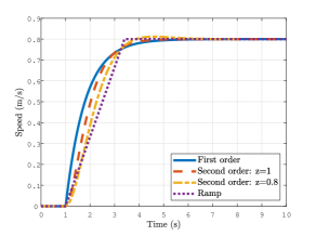
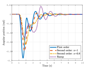
It appeared that with a second-order controller, it was possible to reduce the angular amplitude of the pendulum and decrease the overall acceleration by 8%. However, some preliminary tests, involving three participants trying to follow a path with an admittance controller and a second-order controller, revealed that the second-order controller is not as intuitive as the first order. During tests, the users had to face manoeuvrability issues and lost control of the lift. Because of one more order, the response time was longer in certain cases; it led to a lack of control. For that reason, the user had to force more on the handle to get to the required motion, and the passenger’s comfort was impacted and became worse. Even if the second-order controller was designed to provide better comfort for the patient, it decreases manoeuvrability, and comfort is, contrary to what was expected, getting worse.
The conclusion of all this approach, which has tried to improve the patient’s comfort, is that the user has to perfectly control the lift to improve the patient’s comfort. So, instead of searching to improve comfort, it is preferred to focus the design control on the manoeuvrability aspect of the lift by using variable control strategies.
IV-D Variable Admittance Control
A variable controller consists in changing the admittance law coefficients depending on the situation. The damping coefficient of an admittance control has a simultaneous impact on the response time and the final response of the controller. So, the proposal is to adapt the damping coefficient to the user’s intentions [10].
When the lift is going in one direction and the user is pushing towards the other, he intends to change the direction of the lift. The lift needs to promptly decelerate, which means that the controller needs a high-damping ratio.
| (5) |
Also, when the lift is going towards a specific direction and the user is pushing in the same way, he intends to go faster. The lift must accelerate, and the controller must use a small damping coefficient.
| (6) |
Thus, it is proposed to modify the damping coefficient through a linear equation depending on the sign of the speed and the amplitude of force.
| (7) |
The and coefficients were tuned to get a good behaviour of the lift at low speeds and to have the same sensitivity at maximal speeds than the admittance controller (30 N to get to 0.8 m/s). However, the damping coefficient should be limited to prevent the lift from being too sensitive and hard to control [10]. Regarding these ideas, the coefficients of the damping controller were tuned in function of , the damping coefficient of the classical admittance controller, to compare the classical admittance controller and the variable controller. was set to to get a good behaviour of the lift at low speeds and a good reaction when changing directions. was established to get 0.8 m/s when the user is pushing at , and thus obtain the same speed range than the admittance controller.
| (8) |
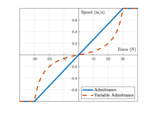
Modifying the damping coefficient has an impact on the lift dynamics, especially on its response time. This comportment ensures a quick reply to the user’s intentions by having a more or less important damping coefficient adapted to the situation. It also has an impact on the final velocity (Equation 9). The non-linearity generated by the varying damping coefficient creates a better resolution of the controller, which allows the user to have a better feeling of manoeuvrability at a low speed. Because it requires a bigger amount of force than a simple admittance controller, it is easier for the user to make small adjustments, thanks to the large variation range of force, which is more spread out than a simple admittance controller. Figure 5 shows the final velocity versus the input force on a classical admittance controller and a variable damping controller, following equations 9. For instance, if the user wants to get to 0.2 m/s, he needs to push the lift with 7.5 N, whereas he needs to push with 20 N with variable damping. The resolution is wider, and this makes the variable damping controller better for small adjustments when positioning the lift next to a chair, for instance. However, variable damping requires more force to get to a certain speed, but the difference is not big enough to be perceived as a drawback.
User tests have been made, and the benefit of variable damping has been confirmed. Some tests in real conditions are required to establish which is the optimal controller between a classical admittance control and a variable control and to quantify the improvement between a motorised and a non-assisted lift.
| (9) |
V PERFORMANCE EVALUATION
The next section explains how the evaluation of the performances of the lift’s different configurations was conducted.
V-A Testing Protocol
The performance evaluation was conducted with seven participants: four men and three women aged 31–56 years, with an average of 40 years.
Each participant was asked to realise a series of 12 patient transfer simulations with different weights and different control configurations.
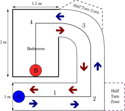
The transfer consists in moving a fake patient from a chair to a simulated bathroom and back to the chair. The goal is to simulate a real case of a patient transfer with the same restrictions in terms of space, positioning and path. The path is inspired from Marras’ article [4]. It is made of a straight part, a sharp turn, a long turn and a last sharp turn when the user is entering a bathroom (Figure 6).The user starts at the A post as if he was picking up someone from a chair. The user starts in a backward position and must back up to the half-turn zone and then turn and walk forward to the B post. Once at B, he can go back to A by using the second half-turn zone again, walking backward to the half-turn zone and then forward to A. Three wooden dummies with a humanoid shape were filled with cast-iron weights and used as simulated patients. They weighed 80 kg, 130 kg and 180 kg, respectively.
The participants tested four different ways to control the lift. The first one was with no assistance at all as if it was a basic floor lift. The second one was with the help of the passive fifth wheel. The motorised wheel was used but unplugged from any electrical source, and it served as a basic wheel. The goal was to see the interest in the passive function of the fifth wheel. The third way to control the lift was by using the motorised wheel linked to an admittance controller, thus connecting to an electrical source. The last one is using the variable damping controller. The order in which the weights were tested was established randomly. The participants were not aware of the simulated patient weight to avoid any cognitive bias on their perception of the lift. The running order of the controllers was also determined randomly for each participant. They were not told which controller they were testing to avoid any cognitive bias.
V-B Data Recording and Process
During each run, data were recorded to evaluate the performance of the lift.
V-B1 Patient Comfort
Patient comfort was recorded by measuring the acceleration on the dummy with inertial measurement units. An MPU-6050 (TDK InvenSense, United States) was used with a frequency of 200 Hz and a moving average of 50 points, and it was linked to an Arduino Mega (Arduino, Italy). The values were directly recorded on a laptop through an HC-05 (DSDTech, China), Bluetooth to serial module. The data were post-treated to calculate the overall acceleration, as previously described, to be used as a performance criterion:
| (10) |
V-B2 Effort Reduction
The effort reduction was quantified through a three-axis load cell. This load cell was made from a specially designed instrumented tube with 10 strain gauges (8 linear and 2 shear) that could measure the longitudinal and lateral forces as well as the torque on the handle. These are the three main efforts needed to compute how the user is soliciting the handle. Each axis was calibrated prior to experiments. The acquisition of the strain bridges was made with the HX711 (Avia, China) load cell amplifiers at a 10 Hz frequency. The acquisition board was an Ardbox (Industrial Shield, Spain), and the recording was made directly on a laptop through a serial USB connection. The integral of the squared force and torque and the cost of effort was then calculated for each run (Equation 11).
| (11) |
V-B3 Manoeuvrability
Manoeuvrability was measured with different data. First, the time needed to realise a transfer was measured to track the performance of each run and see if there was any learning effect between each run. Moreover, some tape was put on the floor to evaluate the amount of space needed to realise a path (dotted lines on Figure 6). Each time the user or the lift stepped outside the zone delimited by the tape on the floor, it was counted as one overshoot, as well as collisions with walls or doorways. The participants did not know that the number of steps outside the zone was counted to make sure they do not force themselves to stay in the zone and avoid any cognitive bias. The number of overshoot gave an approximation of the space needed to perform a transfer with every lift configuration tested. The latter, coupled with the time needed to perform the transfer, was used to compare manoeuvrability.
V-B4 Qualitative Feedback
After each run, the participants were asked to review the transfer. They were asked to give grades on a scale of 1–10 about their appreciation of the effort (10 being no effort needed), their feeling of control (10 meaning being in full control) and their global appreciation. The participants could ask for revised grades after the transfers.

VI EXPERIMENTAL RESULTS
The results are presented in Figure 7. Each column represents the mean, and an error bar indicates the standard deviation of each criterion for all the different runs of the participants. The Student paired t-test was used to determine if the difference in mean values between each lift configuration is significant. The null hypothesis was rejected if . Statistical tests were performed using the Excel statistics toolbox (Microsoft, USA).
VI-A Effort Reduction
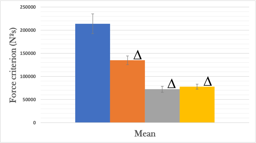
Figure 7(a) shows the squared integrals of force for each participant with the different lift configurations. Each bar represents the average of the three runs at 80, 130 and 180 kg. As might be expected, there was a high diminution of effort between the unassisted lift and the motorised lift. We have an average difference of force of 37% between the unassisted lift and the passive fifth wheel lift and 66% between the unassisted and motorised lifts. Surprisingly, there is a significant diminution between the unassisted and passive fifth wheel lifts on the force criterion. It was expected that the fifth wheel only helps the user in the lift rotation and thus would have only been observed on the torque criterion, which is not the case. One interpretation of this phenomenon would be that it requires less effort to control the lift for all manoeuvres because the fifth wheel is limiting the lateral motions of the lift when turning, especially with heavy patients. When looking at the motorised solutions, the admittance controller and the variable controller have similar levels of force and torque, which is expected since they are tuned to have the same sensibilities at high speed.
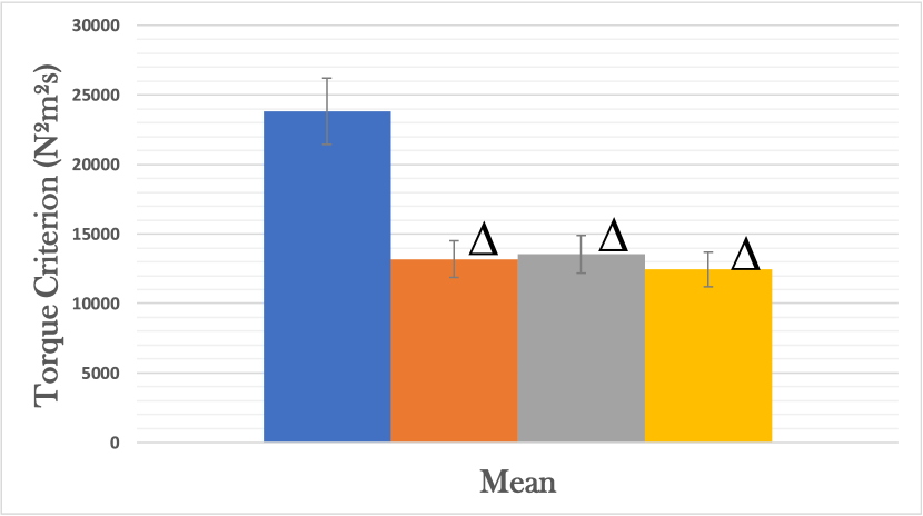
Figure 7(b) shows the squared integrals of the torque at the handle for each participant. There is a significant difference of 45% between the unassisted lift and the other configurations. This difference is due to the fifth wheel that procures an amplification of the hand force when turning the lift, especially in confined spaces where there is no freedom for the user to find a better position to turn the lift. There is no clear difference between the passive fifth wheel lift and the two controllers (p-value ) that could ensure that one is better than the other in terms of torque. By using a motorised fifth wheel, the force and the torque required to push the lift have been decreased by 66% and 45%, respectively.
VI-B Passenger Comfort
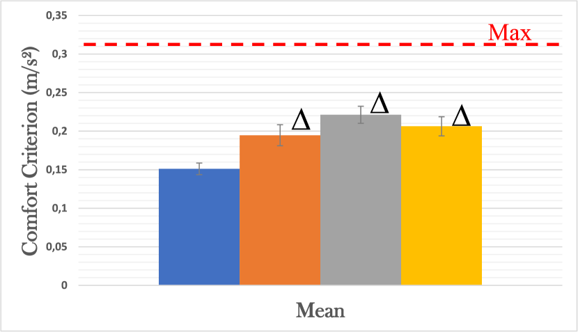
Figure 7(c) is the overall acceleration for each participant. Each bar represents the average of the three different weights. The red dotted line represents a limit of recommended by the ISO-2631-1:1997, which must not be exceeded to ensure a comfortable transfer for the patient. When comparing the acceleration of the different users, it appears that the unassisted lift is more comfortable than the assisted lift. There is a 32% difference in average between the admittance controller and the unassisted lift. There is one principal reason that could explain this gap. When using the fifth wheel, all the rotations are made around the pivot axis of the fifth wheel and the passenger is moving around this axis. When using the classical lift with only four swivel wheels, the user will tend to turn around the centre of gravity of the passenger because it is easier than making the passenger move, but it will take more space to manoeuvre. The amplitude of motion is consequently bigger when using the fifth wheel than when using a simple lift. The overall acceleration is therefore deteriorated. The passive fifth wheel, the admittance controller and the variable controller have globally the same overall acceleration. Depending on the user, one is better than the others, which is due to the correct understanding of the lift in each case. The average difference between these three configurations is not large enough, and the trends are not constant between each user (p-value ) to make a clear conclusion about which configuration is the best in terms of comfort. However, each controller can be characterised as comfortable because they all have an acceleration under .
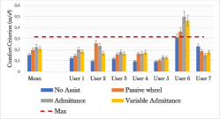
Figure 8 shows the results for each participant, highlighting that user 6 has exceeded the comfort limit of 0.315 m/s2. It was observed during the protocol that this participant was less delicate with the simulated patient than the other users, which had an impact on the overall acceleration. Even if the controller is tuned to optimise the comfort of the patient, the overall comfort is greatly influenced by the behaviour of the caregiver handling the lift. In this case, the user was manoeuvring the lift roughly, which had a bad impact on the patient’s swing. This can be seen as a limitation of using dummies instead of real people as simulated patients.
VI-C Manoeuvrability
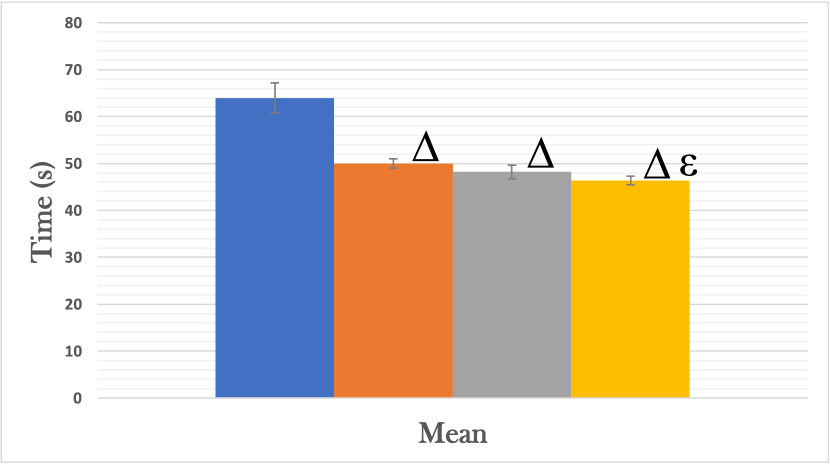
Figure 7(g) is the time taken by each user to perform the transfer depending on the lift configuration. It occurs that the passive fifth wheel lift is 14 seconds faster than the unassisted lift. The average time to realise the path with the unassisted lift is about 64 seconds, whereas it takes 50 seconds with the passive fifth wheel lift. It has been observed during the experiments that people tend to lose control of the lift due to the inertial force of the simulated patient when performing sharp turns with the No Assist lift. The time to complete the transfer is consequently increased. There is a more subtle difference of 1.2 seconds between the passive fifth wheel and the admittance controller. The time to perform the transfer is broadly the same, but the admittance controlled lift is easier to start and stop because the wheel is helping to push the lift. Consequently, the admittance controller feels easier to drive and more manoeuvrable. Moreover, the average time to execute the path with the variable damping controller is about 46.4 seconds, which is 1.8 seconds faster than with the fixed admittance controller. This improvement could be due to two advantages of variable damping compared to fixed damping. First, it has good reactivity: When the user wants to stop the lift or change direction, the damping ratio increases and the time constant decreases, leading to a quicker reaction time of the lift to the user’s intention. Second, variable damping has higher sensitivity at low speeds due to the high-damping ratio when the user is pushing softly. This sensitivity improves the ability to perform precise movements for manoeuvres, like entering the bathroom’s doorway or placing the simulated patient on the chair (post A) or on the toilet (post B). These advantages make the variable admittance controller the fastest of the four lift configurations.
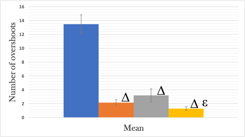
Figure 7(h) represents the number of overshoots observed during the tests. The unassisted lift has an average number of overshoots of 14 per run, which is approximately four times the number of overshoots with a fifth wheel, motorised or not. This illustrates the trouble it is to manipulate a simple lift without any assistance. Because the lift is mounted on four swivelling casters, it requires more strength to manipulate the lift to counter the inertial force and to compensate for the disturbance caused by the swivelling wheels. The participants tend to constantly change position around the lift to reduce the lower back effort needed to push the lift, which leads to an important number of steps outside the delimited zone. This behaviour becomes laborious when the participant is in a restricted space, for instance, the simulated bathroom in this experience. When using the passive fifth wheel, the number of overshoot is small (mean of 2.2 for the passive fifth wheel, 3.2 for the admittance controller and 1.3 for the variable controller). The variable controller has the lowest number of overshoot (40% of difference with the passive fifth wheel lift) due to its short reaction time, which helps a lot in controlling the lift and making the user not overstep and get better control.
VI-D Qualitative feedback
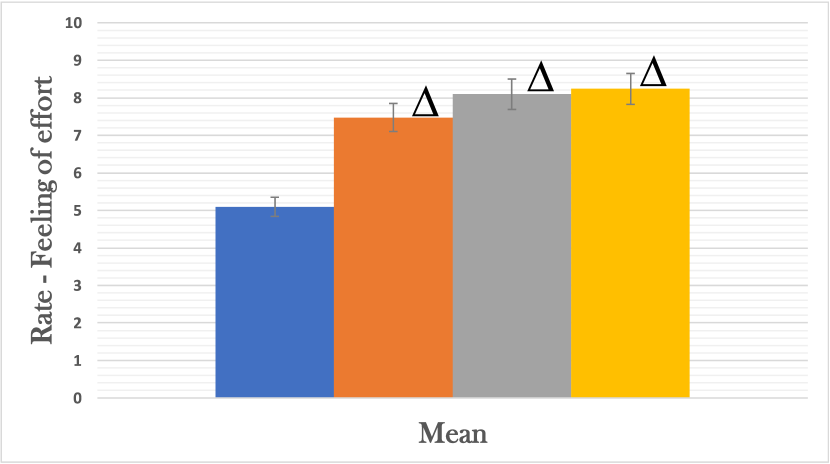
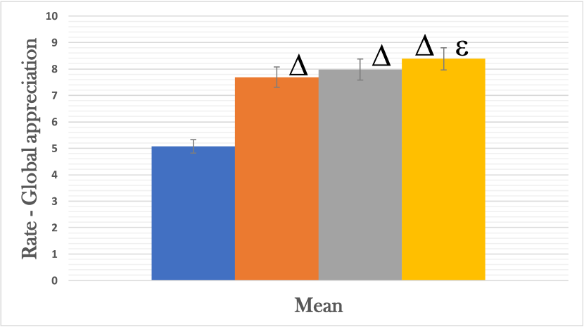
Figure 7(d), 7(e), and 7(f) are the different ratings given by the participants on their appreciation of effort and control and their global appreciation of the lifts’ behaviours.
All the users were able to feel a significant difference in terms of effort between the unassisted lift and the passive fifth wheel lift as well as between the passive fifth wheel lift and the motorised controller. There is 32% difference between the unassisted and passive fifth wheel lifts and 8% between the passive fifth wheel lift and the admittance controller. However, they were not able to note any difference between the admittance controller and the variable controller (2% of difference, p-value ), even if the measured data shows otherwise, as described above.
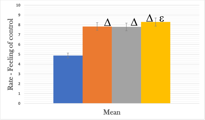
Regarding the appreciation of control, all participants found that the unassisted lift is challenging to use for transferring a patient in comparison to the others. There is a 38% rating difference between the unassisted and passive fifth wheel lifts. The admittance controller and the passive fifth wheel lift were similarly appreciated (difference , p-value ), although the variable controller was preferred for its dynamic response. There is a 6% rating difference between the variable and fixed admittance controllers and 5% between the variable admittance controller and the passive fifth wheel lift.
The global appreciation is close to the average of the two previous criteria. The participants naturally tend to give an average between the sensation of effort and the feeling of control. Variable damping was preferred compared to the fixed admittance controller (5% of difference) for its manoeuvrability. The admittance controllers are more appreciated than the passive fifth wheel lift (4% of difference) for its reduction of effort, which matches the comments collected during the activity.
VII DISCUSSION
The main purpose of this work was to develop a controller for a motorised fifth wheel added to a patient transfer device and to experimentally validate its performance in a realistic patient transfer simulation. To our knowledge, this is the first study covering the controller design of motorised fifth wheel and an extensive experimental validation with realistic scenarios. Through the presented results, the designed variable admittance controller and the value of the motorised fifth wheel have proven to be significantly superior to the classical floor lift with four swivelling casters.
The safety of the user is improved, thanks to the diminution of the amount of effort required to push the lift. The fifth wheel allows a significant reduction of 66% of force and 45% of torque at the handle. The motorised wheel significantly lowers the force needed to manoeuvre the lift, especially when starting and stopping the lift. Without motorised assistance, results showed that values between 80 N and 190 N are required to start the lift depending on the weight of the simulated patient, whereas less than 20 N is required with motorised assistance.
From Figure 7(f), it is interesting to note that the fifth wheel, even passive, provides an improvement in the control of the lift, allowing a diminution of the effort, manoeuvrability and control. With a fifth wheel, the lift is more stable and has less tendency to drift. Therefore, the caregiver does not need to constantly reposition or use back strains to counterbalance the bad behaviour of the swivel wheels. Moreover, the rotation of the lift is performed around the axis of the fifth wheel, and due to its central position, the force applied by the user to rotate is amplified, thanks to the lever-arm effect.
The manoeuvrability is also improved. The time required to perform a transfer has been decreased by more than 22% in comparison to the unassisted lift, as well as the space needed for a user to perform a transfer. Thanks to the constant orientation of the wheel, the lift is constrained, and most of the inertial effects that lead to a drift of the lift are stopped.
However, the comfort of the passenger was slightly deteriorated with the integration of the fifth wheel, passive and motorised. The overall acceleration has been increased but did not exceed the limit stated in the ISO-2631-1:1997. Due to the central position of the fifth wheel, the lift pivots around the axis of the wheel, and the passenger consequently moves around this axis. Therefore, the amplitude of motion of the passenger is somewhat higher than when using the unassisted lift. With an unassisted lift, the turning phase is performed mainly around the centre of gravity of the system, which is near the patient’s centre of gravity. The advantage of rotating around the patient is that the patient do not swing much, but the downside is that much more space and more time are needed to perform the transfer. This difference in swinging was expected, and the controllers were tuned accordingly. Yet, the behaviour of one particular participant showed that the caregiver using the lift has a large influence in the comfort of the patient.
In this study, it is interesting to note that the conclusions from the measured data are confirmed by the users’ feedback and perception. The difference in effort was measured by the sensors and rated by the participants, as well as the difference in control between each lift configurations. All participants agreed that there is value in the motorisation of a fifth wheel for the patient’s transfer lift. However, it is interesting to observe that certain differences that were measured were not perceived as big as they are by the participants. For instance, the difference in force between the passive fifth wheel and the admittance controller is 47% whereas the difference in ratings among the participants is only 8%. This is due to the fact that the criterion amplifies the difference, which is useful in analysing the different behaviours of the controllers but might be less loyal to the reality. Also, the participants focused more on the ease to turn the lift and, consequently, on the torque criterion than on the ease to push and pull because it feels more demanding to turn the lift than push it. One other drawback about the participants is that they were not professional caregivers, and some key elements that a real caregiver could have seen might have been missed. Finally, it would have been interesting to have a real simulated patient instead of articulated wooden dummies filled with weights to have a qualitative feedback and to quantify a difference in comfort between each controller in terms of feelings and sensations. Moreover, participants may have behaved differently with a living simulated patient by looking more into the patient comfort.
Even though the passive fifth wheel lift has good results, there is a real interest to use a motorised wheel instead of a passive wheel. The motorised wheel significantly reduces the needed effort and enhances manoeuvrability, which has been confirmed by the participants’ feedback. The variable damping controller stands out from the fixed admittance controller by offering significantly more manoeuvrability efficiently and a higher appreciation by the participants.
VIII CONCLUSIONS
This paper introduces a motorised floor lift and its control algorithms to introduce a new kind of patient transfer device. It is composed of a fifth-motorised wheel that helps the user moving the lift and the patient easily.
Tests with seven participants were performed to experimentally evaluate the performance of the assistance system and the controllers. Different lift configurations were explored: an unassisted lift with no assistance, a passive fifth wheel added in front of the column, a motorised fifth wheel lift controlled by a classical admittance algorithm and a motorised fifth wheel lift with a variable admittance control algorithm. The experimental results show that motorised assistance with the variable controller improves manoeuvrability, reduces the amount of effort required to push the lift by 66% and preserves the patient’s comfort in comparison to a standard unassisted floor lift. The variable admittance controller was preferred by the participants in comparison to the classical admittance controller because the system reacts with a more intuitive response to the user’s intentions, which improves manoeuvrability and facilitates the transfer of the patient.
The next step is to introduce the motorised lift in a hospital environment to investigate the performance when exposed to various real external factors, and to compare the motorized fifth wheel concept to the already existing motorized floor lift solutions.
IX Acknowledgements
This project was financed by CoRoM, a NSERC-CREATE training program specialised in collaborative robotics.
References
- [1] K. G. Davis and S. E. Kotowski, “Prevalence of Musculoskeletal Disorders for Nurses in Hospitals, Long-Term Care Facilities, and Home Health Care: A Comprehensive Review,” Human Factors, vol. 57, no. 5, pp. 754–792, Aug. 2015.
- [2] M. C. Callison and M. A. Nussbaum, “Identification of physically demanding patient-handling tasks in an acute care hospital,” International Journal of Industrial Ergonomics, vol. 42, no. 3, pp. 261–267, May 2012.
- [3] D. Daynard, A. Yassi, J. E. Cooper, R. Tate, R. Norman, and R. Wells, “Biomechanical analysis of peak and cumulative spinal loads during simulated patient-handling activities: a substudy of a randomized controlled trial to prevent lift and transfer injury of health care workers,” Applied Ergonomics, vol. 32, no. 3, pp. 199–214, Jun. 2001.
- [4] W. S. Marras, G. G. Knapik, and S. Ferguson, “Lumbar spine forces during manoeuvring of ceiling-based and floor-based patient transfer devices,” Ergonomics, vol. 52, no. 3, pp. 384–397, Mar. 2009.
- [5] G. G. Knapik and W. S. Marras, “Spine loading at different lumbar levels during pushing and pulling,” Ergonomics, vol. 52, no. 1, pp. 60–70, Jan. 2009.
- [6] “PowerMOVE Tilliften Producten JOYinCARE Hulpmiddelen voor de zorg.” [Online]. Available: https://joyincare.com/producten/tilliften/powermove
- [7] “EvaDrive - Handicare International.” [Online]. Available: https://www.handicare.ca/product/evadrive/
- [8] Z. Guo, X. Xiao, and H. Yu, “Design and Evaluation of a Motorized Robotic Bed Mover With Omnidirectional Mobility for Patient Transportation,” IEEE Journal of Biomedical and Health Informatics, vol. 22, no. 6, pp. 1775–1785, Nov. 2018.
- [9] R. Solea and U. Nunes, “Robotic Wheelchair Control Considering user Comfort - Modeling and Experimental Evaluation.” vol. 1, Jan. 2008, pp. 37–44.
- [10] V. Duchaine, B. Mayer St-Onge, D. Gao, and C. Gosselin, “Stable and Intuitive Control of an Intelligent Assist Device,” IEEE Transactions on Haptics, vol. 5, no. 2, pp. 148–159, Apr. 2012.
- [11] J. Rosen, M. Brand, M. Fuchs, and M. Arcan, “A myosignal-based powered exoskeleton system,” IEEE Transactions on Systems, Man, and Cybernetics - Part A: Systems and Humans, vol. 31, no. 3, pp. 210–222, May 2001.
- [12] S. A. Reid and G. A. Mirka, “Learning curve analysis of a patient lift-assist device,” Applied Ergonomics, vol. 38, no. 6, pp. 765–771, Nov. 2007.
- [13] “ISO 10535:2006 Hoists for the transfer of disabled persons — Requirements and test methods.”
- [14] E. B. Weston, S. N. Khan, and W. S. Marras, “Wheelchair pushing and turning: lumbar spine and shoulder loads and recommended limits,” Ergonomics, vol. 60, no. 12, pp. 1754–1765, Dec. 2017.
- [15] “ISO 2631-1:1997-Mechanical vibration and shock — Evaluation of human exposure to whole-body vibration — Part 1: General requirements.”
- [16] Sehoon Oh and Y. Hori, “Sensor Free Power Assisting Control Based on Velocity Control and Disturbance Observer,” in Proceedings of the IEEE International Symposium on Industrial Electronics, 2005. ISIE 2005., vol. 4, Jun. 2005, pp. 1709–1714, iSSN: 2163-5145.
- [17] M. Spong, “Partial feedback linearization of underactuated mechanical systems,” in Proceedings of IEEE/RSJ International Conference on Intelligent Robots and Systems (IROS’94), vol. 1. Munich, Germany: IEEE, 1994, pp. 314–321.