Two New Piggybacking Designs with Lower Repair Bandwidth
Abstract
000 Zhengyi Jiang and Zhongyi Huang are with the Department of Mathematics Sciences, Tsinghua University (E-mail: jzy21@mails.tsinghua.edu.cn, zhongyih@tsinghua.edu.cn). Hanxu Hou and Bo Bai are with Theory Lab, Central Research Institute, 2012 Labs, Huawei Technology Co. Ltd. (E-mail: houhanxu@163.com, baibo8@huawei.com). Yunghsiang S. Han is with the Shenzhen Institute for Advanced Study, University of Electronic Science and Technology of China (E-mail: yunghsiang@gmail.com). Patrick P. C. Lee is with the Department of Computer Science and Engineering, The Chinese University of Hong Kong (E-mail: pclee@cse.cuhk.edu.hk). This work was partially supported by the National Key R&D Program of China (No. 2020YFA0712300), National Natural Science Foundation of China (No. 62071121, No.12025104, No.11871298), Research Grants Council of HKSAR (AoE/P-404/18), Innovation and Technology Fund (ITS/315/18FX).Piggybacking codes are a special class of MDS array codes that can achieve small repair bandwidth with small sub-packetization by first creating some instances of an MDS code, such as a Reed-Solomon (RS) code, and then designing the piggyback function. In this paper, we propose a new piggybacking coding design which designs the piggyback function over some instances of both MDS code and MDS code, when . We show that our new piggybacking design can significantly reduce the repair bandwidth for single-node failures. When , we design a piggybacking code that is MDS code and we show that the designed code has lower repair bandwidth for single-node failures than all existing piggybacking codes when the number of parity node and the sub-packetization .
Moreover, we propose another piggybacking codes by designing piggyback functions of some instances of MDS code and adding the piggyback functions into the newly created empty entries with no data symbols. We show that our code can significantly reduce repair bandwidth for single-node failures at a cost of slightly more storage overhead. In addition, we show that our code can recover any node failures for some parameters. We also show that our code has lower repair bandwidth than locally repairable codes (LRCs) under the same fault-tolerance and redundancy for some parameters.
Index Terms:
Piggybacking, MDS array code, repair bandwidth, storage overhead, sub-packetization, fault toleranceI Introduction
Maximum distance separable (MDS) array codes are widely employed in distributed storage systems that can provide the maximum data reliability for a given amount of storage overhead. An MDS array code encodes a data file of data symbols to obtain coded symbols with each of the nodes storing symbols such that any out of nodes can retrieve all data symbols, where and . The number of symbols stored in each node, i.e., the size of , is called sub-packetization level. We usually employ systematic code in practical storage systems such that the data symbols are directly stored in the system and can be retrieve without performing any decoding operation. Note that Reed-Solomon (RS) codes [1] are typical MDS codes with .
In modern distributed storage systems, node failures are common and single-node failures occur more frequently than multi-node failures [2]. When a single-node fails, it is important to repair the failed node with the repair bandwidth (i.e,. the total amount of symbols downloaded from other surviving nodes) as small as possible. It is shown in [3] that we need to download at least symbols from each of the surviving nodes in repairing one single-node failure. MDS array codes with minimum repair bandwidth for any single-node failure are called minimum storage regenerating (MSR) codes. There are many constructions of MSR codes to achieve minimum repair bandwidth in the literature [4, 5, 6, 7, 8, 9, 10, 11]. However, the sub-packetization level of high-code-rate (i.e., ) MSR codes [9] is exponential in parameters and . A nature question is that can we design new MDS array codes with both sub-packetization and repair bandwidth as small as possible.
Piggybacking codes [12, 13] are a special class of MDS array codes that have small sub-packetization and small repair bandwidth. The essential idea behind the piggybacking codes [13] is as follows: by creating instances of RS codes and adding carefully well-designed linear combinations of some symbols as so-called piggyback functions from one instance to the others, we can reduce the repair bandwidth of single-node failure. Some further studies of piggybacking codes are in [14, 15, 16, 17, 18, 19].
The existing piggybacking codes are designed based on some instances of an RS codes. The motivation of this paper is to significantly reduce the repair bandwidth by designing new piggybacking codes. In this paper, we propose new piggybacking codes by first creating some instances of both MDS code and MDS code, and then designing the piggyback functions that can significantly reduce repair bandwidth for single-node failures, when .
I-A Contributions
Our main contributions are as follows.
-
•
First, we propose a new type of piggybacking coding design which is designed by both MDS code and MDS code, where . We give an efficient repair method for any single-node failure for our piggybacking coding design and present an upper bound on repair bandwidth. When , our codes are non-MDS codes and we show that our codes have much less repair bandwidth than that of existing piggybacking codes at a cost of slightly more storage overhead. The essential reason of repair bandwidth reduction of our codes is that we have more design space than that of existing piggybacking codes.
-
•
Second, when , we design new piggybacking codes that are MDS codes based on the proposed design. We show that the proposed piggybacking codes with have lower repair bandwidth than that of the existing piggybacking codes when and the sub-packetization is less than .
-
•
Third, we design another piggybacking codes by designing and adding the piggyback functions into the newly created empty entries with no data symbols. We show that our piggybacking codes can tolerant any node failures under some conditions. We also show that our codes have lower repair bandwidth than that of both Azure-LRC [20] and optimal-LRC [21] under the same fault-tolerance and the same storage overhead for some parameters.
I-B Related Works
Many works are designed to reduce the repair bandwidth of erasure codes which we discuss as follows.
I-B1 Piggybacking Codes
Rashmi et al. present the seminal work of piggybacking codes [12, 13] that can reduce the repair bandwidth for any single-data-node with small sub-packetization. Another piggybacking codes called REPB are proposed [15] to achieve lower repair bandwidth for any single-data-node than that of the codes in [13]. Note that the piggybacking codes in [13, 15] only have small repair bandwidth for any single-data-node failure, while not for parity nodes. Some follow-up works [16, 18, 19] design new piggybacking codes to obtain small repair bandwidth for both data nodes and parity nodes. Specifically, when and sub-packetization is , OOP codes [16] have the lowest repair bandwidth for any single-node failure among the existing piggybacking codes; when and sub-packetization is , the codes in [19] have the lowest repair bandwidth for any single-node failure among the existing piggybacking codes.
Note that all the existing piggybacking codes are designed over some instances of an MDS code. In this paper, we design new piggybacking codes that are non-MDS codes over some instances of both MDS code and MDS codes with that have much lower repair bandwidth for any single-node failures at a cost of slightly larger storage overhead.
I-B2 MDS Array Codes
Minimum storage regenerating (MSR) codes [3] are a class of MDS array codes with minimum repair bandwidth for a single-node failure. Some exact-repair constructions of MSR codes are investigated in [4, 22, 5, 6, 23, 8, 10, 11]. The sub-packetization of high-code-rate MSR codes [5, 23, 8, 10, 11] is exponentially increasing with the increasing of parameters and . Some MDS array codes have been proposed [24, 25, 26, 27, 28, 29] to achieve small repair bandwidth under the condition of small sub-packetization; however, they either only have small repair bandwidth for data nodes [24, 25, 30, 26, 27] or require large field sizes [28, 29].
I-B3 Locally Repairable Codes
Locally repairable codes (LRCs) [20, 31] are non-MDS codes that can achieve small repair bandwidth for any single-node failure with sub-packetization by adding some local parity symbols. Consider the Azure-LRC [20] that is employed in Windows Azure storage systems, we first create global parity symbols by encoding all data symbols, divide the data symbols into groups and then create one local parity symbol for each group, where is a multiple of . In the Azure-LRC, we can repair any one symbol except global parity symbols by locally downloading the other symbols in the group. Optimal-LRC [21, 32, 33, 34] is another family of LRC that can locally repair any one symbol (including the global parity symbols). One drawback of optimal-LRC is that existing constructions [21, 32, 33, 34] can not support all the parameters and the underlying field size should be large enough. In this paper, we propose new piggybacking codes by designing and adding the piggyback functions into the newly created empty entries with no data symbols that are also non-MDS codes and we show that our piggybacking codes have lower repair bandwidth when compared with Azure-LRC [20] and optimal-LRC under the same storage overhead and fault-tolerance, for some parameters.
The remainder of this paper is organized as follows. Section II presents two piggybacking coding designs. Section III shows new piggybacking codes with based on the first design. Section IV shows another new piggybacking codes based on the second design. Section V evaluates the repair bandwidth for our piggybacking codes and the related codes. Section VI concludes the paper.
II Two Piggybacking Designs
In this section, we first present two piggybacking designs and then consider the repair bandwidth of any single-node failure for the proposed piggybacking codes.
II-A Two Piggybacking Designs
Our two piggybacking designs can be represented by an array, where is a positive integer, the symbols in each row are stored in a node, and . We label the index of the rows from 1 to and the index of the columns from 1 to . Note that the symbols in each row are stored at the corresponding node.
In the following, we present our first piggybacking design. In the piggybacking design, we first create instances of MDS codes plus one instance of MDS codes and then design the piggyback functions, where . We describe the detailed structure of the design as follows.
-
1.
First, we create instances of MDS codes over finite field , the first columns are the codewords of MDS codes and the last column is a codeword of MDS codes, where , and . Let be the data symbols in the first columns and be codeword of the MDS codes, where and with and is a primitive element of . Let be the data symbols in the last column and be a codeword of an MDS code, where with . Note that the total number of data symbols in this code is .
-
2.
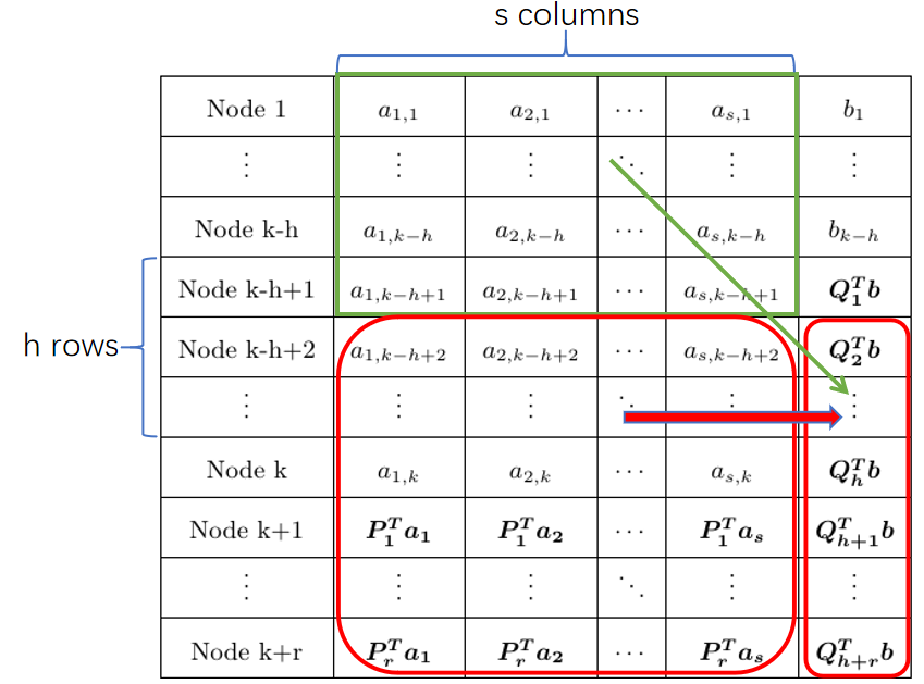
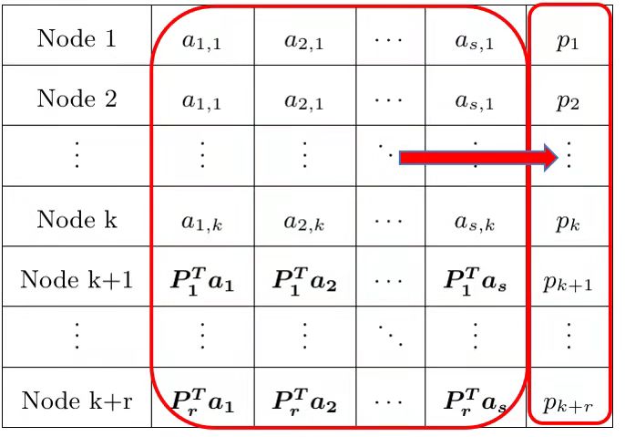
Second, we add the piggyback functions of the symbols in the first columns to the parity symbols in the last column, in order to reduce the repair bandwidth. We divide the piggyback functions into two types: piggyback functions of the symbols in the first rows in the first columns; piggyback functions of the symbols in the last rows in the first columns. Fig. 1 shows the structure of two piggyback functions. For the first type of the piggyback functions, we add symbol (the symbol in row and column ) to the parity symbol (the symbol in row in the last column), where and . For the second type of the piggyback functions, we add the symbol in row and column with and to the parity symbol (the symbol in row in the last column), where
(1)
The first piggybacking design described above is denoted by . When , we have and the created instances are codewords of MDS codes. We will show the repair bandwidth in Section III.
We present the second piggybacking design as follows. We create instances (in the first columns) of MDS codes over finite field and one additional empty column of length , i.e., there is no data symbol in the last column, all the entries in the last columns are piggyback functions. We design the piggyback functions in the last column as follows. For and , we add the symbol in row and column to the symbol in row in the last column, where
| (2) |
We denote the second piggybacking design by , the last parameter denotes that there is not data symbol in the last column. We will discuss the repair bandwidth in Section IV.
Recall that in our first piggybacking design, the number of symbols to be added with piggyback functions in the last column is and such that we can see that any two symbols used in computing both types of piggyback functions are from different nodes. Since
the symbol in row with and column with is not added to the symbol in row and column in computing the second type of piggyback functions. In our second piggybacking design, since
the symbol in row with and column with is not added to the symbol in row and column in computing the piggyback functions.
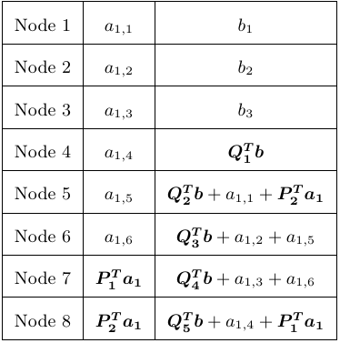
It is easy to see the MDS property of the first piggybacking design . We can retrieve all the other symbols in the first columns from any nodes (rows). By computing all the piggyback functions and subtracting all the piggyback functions from the corresponding parity symbols, we can retrieve all the symbols in the last column. Fig. 2 shows an example of .
Note that the piggyback function of the second piggybacking design is different from that of the first piggybacking design. In the following of the section, we present the repair method for the first piggybacking design. We will show the repair method for the second piggybacking design in Section IV.
For , let be the piggyback function added on the parity symbol and be the number of symbols in the sum in computing piggyback function . According to the design of piggyback functions, we have two set of symbols that are used in computing the piggyback functions. The first set contains symbols (in the first rows and in the first columns) and the second set contains symbols (in the last rows and in the first columns). We have that the total number of symbols used in computing the piggyback functions is , i.e.,
| (3) |
In our first piggybacking design, the number of symbols used in computing each piggyback function is given in the next lemma.
Lemma 1.
In the first piggybacking design with , the number of symbols used in computing the piggyback function is
| (4) |
Proof.
In the design of the piggyback function, we add the symbol in row and column for and ( symbol in the first set) to the symbol in row (piggyback function ) in the last column. Therefore, we can see that the symbols in row and column are added to for all , and is a multiple of . Note that
we need to choose the symbol in row and column for , such that is a multiple of for all . The number of symbols in the first set used in computing is . Given integer with , we add the symbol in row and column for , such that is a multiple of for all to . The number of symbols in the first set used in computing is if and if . Therefore, the number of symbols in the first set used in computing is if and if .
For the symbols in the second set, we add the symbol in row and column with and to the symbol in row (piggyback function ) in the last column, where is given in Eq. (1). Consider the piggyback function , i.e., . When , according to Eq. (1), only when for , we can obtain . When , according to Eq. (1), only when for , we can obtain . Similarly, for any with , only when for , we can obtain . Since , we have , which is within . In other words, for any with , we can find one and only one with such that . The number of symbols in the second set used in computing is . Similarly, we can show that the number of symbols in the second set used in computing is for all . Therefore, the total number of symbols used in computing is for and for . ∎
Next lemma shows that any two symbols in one row in the first columns are used in computing two different piggyback functions.
Lemma 2.
In the first piggybacking design, if , then the symbol in row in column and the symbol in row in column are used in computing two different piggyback functions, for any and .
Proof.
When , we add the symbol in row and column to the symbol in row in the last column. Similarly, the symbol in row and column is added to the symbol in row in the last column. Suppose that the two symbols in row and columns are added to the same piggyback function, we obtain that , i.e., , which contradicts to and .
When , we add two symbols in row column and row column to the symbol in the last column in row and row , respectively, where and
Suppose that the two symbols in row and columns are added to the same piggyback function, we obtain that . If and , we have that which contradicts to . If and , we have that which contradicts to and . Similarly, we can obtain a contradiction if and . If and , we have that which contradicts to . Therefore, in our first piggybacking design, any two symbols in the same row are not used in computing the same piggyback function. ∎
II-B Repair Process
In the fisrt piggybacking design, suppose that node fails, we present the repair procedure of node as follows, where .
We first consider that , each of the first symbols stored in node is used in computing one piggyback function and we denote the corresponding piggyback function associated with symbol by , where and . We download symbols in the last column from nodes to recover symbols when , or when , according to the MDS property of the last instance. By Lemma 2, any two symbols in one row are used in computing two different piggyback functions. The piggyback function is computed by symbols, where one symbol is and the other symbols are not in node (row ). Therefore, we can repair the symbol in node by downloading the parity symbol and symbols which are used to compute except , where . The repair bandwidth is symbols.
When , each of the first symbols stored in node is used in computing one piggyback function and we denote the corresponding piggyback function associated with the symbol in row and column by , where and . We download symbols in the last column from nodes to recover symbols , according to the MDS property of the last instance. Recall that any symbol in row in the first columns is not used in computing the piggyback function in row . We can recover the last symbol stored in node by downloading symbols which are used to compute the piggyback function . Recall that any two symbols in one row are used in computing two different piggyback functions by Lemma 2. The piggyback function is computed by symbols, where one symbol is in row column and the other symbols are not in node (row ). We can repair the symbol in row and column , for , by downloading symbol and symbols which are used to compute except the symbol in row and column . The repair bandwidth is symbols.
Consider the repair method of the code in Fig. 2. Suppose that node 1 fails, we can first download 3 symbols to obtain the two symbols , according to the MDS property. Then, we download the following 2 symbols
to recover . The repair bandwidth of node 1 is 5 symbols. Similarly, we can show that the repair bandwidth of any single-node failure among nodes 2 to 4 is 5 symbols.
Suppose that node 5 fails, we can download the 3 symbols to obtain , according to the MDS poverty. Then, we download the 2 symbols to recover . Finally, we download the 2 symbols to recover . The repair bandwidth of node 5 is 7 symbols. Similarly, we can show that the repair bandwidth of any single-node failure among nodes 6 to 8 is 7 symbols.
II-C Average Repair Bandwidth Ratio of Code
Define the average repair bandwidth of data nodes (or parity nodes or all nodes) as the ratio of the summation of repair bandwidth for each of data nodes (or parity nodes or all nodes) to the number of data nodes (or the number of parity nodes or the number of all nodes ). Define the average repair bandwidth ratio of data nodes (or parity nodes or all nodes) as the ratio of the average repair bandwidth of data nodes (or parity nodes or all nodes) to the number of data symbols.
In the following, we present an upper bound of the average repair bandwidth ratio of all nodes, denoted by , for the proposed codes when .
Theorem 3.
When , the average repair bandwidth ratio of all nodes, , of codes , is upper bounded by
where .
Proof.
Suppose that node fails, where , we will count the repair bandwidth of node as follows. Recall that the symbol in row and column is used to compute the piggyback function , where and . Recall also that the number of symbols in the sum in computing piggyback function is . When , according to the repair method in Section II-B, the repair bandwidth of node is symbols. When , according to the repair method in Section II-B, the repair bandwidth of node is symbols. The summation of the repair bandwidth for each of the nodes is
| (5) |
Next, we show that
| (6) |
Note that is the summation of the repair bandwidth for each of the symbols in the first columns. The symbols are used to compute the piggyback functions and each symbol is used for only one piggyback function. For , the piggyback function is the summation of the symbols in the first columns and can recover any one of the symbols (used in computing ) with repair bandwidth symbols. Therefore, the summation of the repair bandwidth for each of the symbols (used in computing ) is . In other words, the summation of the repair bandwidth for each of the symbols in the first columns is the summation of the repair bandwidth for each of all the symbols used for computing all piggyback functions, i.e., Eq. (6) holds.
Define storage overhead to be the ratio of total number of symbols stored in the nodes to the total number of data symbols. We have that the storage overhead of codes satisfies that
III Piggybacking Codes
In this section, we consider the special case of codes with . When , we have and the created instances are codewords of MDS codes and the codes are MDS codes. The structure of is shown in Fig. 3.
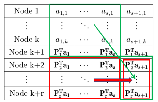
In , we have piggyback functions , and each piggyback function is a linear combination of symbols that are located in the first columns of the array, where . According to Eq. (3), we have
| (7) |
The average repair bandwidth ratio of all nodes of is given in the next theorem.
Theorem 4.
The lower bound and the upper bound of the average repair bandwidth ratio of all nodes of is
| (8) | |||
| (9) |
respectively.
Proof.
According to Theorem 4, the difference between the lower bound and the upper bound of the average repair bandwidth ratio satisfies that
| (10) |
When , the difference between and can be ignored. When , we present the repair bandwidth for as follows.
Corollary 5.
Let and , then the minimum value of the average repair bandwidth ratio of is achieved when .
Proof.
Note that should be a positive integer, we can let or , and then choose the minimum value of the average repair bandwidth ratio for .
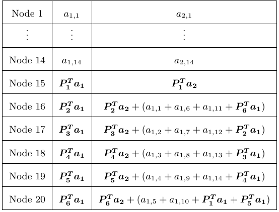
Consider a specific example of code in Fig. 4. Suppose that node 1 fails, we can first download 14 symbols to obtain the two symbols , according to the MDS property. Then, we download the following 4 symbols
to recover . The repair bandwidth of node 1 is 18 symbols. Similarly, we can show that the repair bandwidth of any single-node failure among nodes 2 to 15 is 18 symbols.
Suppose that node 16 fails, we can download the 14 symbols to obtain , according to the MDS poverty. Then, we download the 4 symbols to recover . Finally, we download the 4 symbols to recover . The repair bandwidth of node 16 is 22 symbols. Similarly, we can show that the repair bandwidth of any single-node failure among nodes 17 to 20 is 22 symbols. Therefore, we know that in this example, the average repair bandwidth ratio of all nodes is .
IV Piggybacking Codes
In this section, we consider the special case of codes with based on the second piggybacking design. Recall that there is no data symbol in the last column and we add the piggyback functions in the last column. Here, for , we use to represent the piggyback function in the last column in row (node) . Fig. 5 shows the structure of codes .
For notational convenience, we denote the parity symbol by in the following, where . Given an integer with , we define by
According to the design of piggyback functions in Section II-A, the symbol is used to compute the piggyback function for and . Therefore, we can obtain that the piggyback function for . For any and , the two symbols in row , columns and are added to two different piggyback functions and , respectively, since for . The next theorem shows the repair bandwidth of codes .
Theorem 6.
The repair bandwidth of codes is .
Proof.
Suppose that node fails, where . Similar to the repair method in Section II-B, we can first repair the piggyback function (the symbol in row and column ) by downloading symbols to repair the symbol . Note that the symbol is used to compute the piggyback function for , we can recover the symbol by downloading and the other symbols used in computing except . Therefore, the repair bandwidth of node is symbols. ∎
By Theorem 6, the average repair bandwidth ratio of is . The storage overhead of is
We show in the next theorem that our codes can recover any failures under some condition.
Theorem 7.
If , then the codes can recover any failures.
Proof.
Suppose that nodes fail, where . In the following, we present a repair method to recover the failed nodes.
For , let be the number of surviving nodes between two failed nodes and , and be the number of surviving nodes between nodes and plus the number of surviving nodes between nodes 1 and , i.e., and . It is easy to see that
Let and without loss of generality, we assume that with . We have for and
where the last inequality comes from that . Therefore, we obtain that .
We are now ready to describe the repair method for the failed nodes. We can first repair one symbol stored in the failed node , some symbols that are used to repair the symbol in node are shown in Fig. 6. Recall that the symbol is located column in node . We claim that node is not a failed node, since . Recall also that . We claim that node is not a failed node, for all , since . Therefore, we can download the symbols to recover the symbol . Once the symbol is recovered, we can recover the other failed symbols in column in nodes , according to the MDS property of the MDS codes.

Next, we present a repair method to recover the symbol . First, recall that
node is not a failed node for all and the symbol has already recovered. Therefore, we can recover by downloading the following symbols
Once the symbol is recovered, we can recover the other failed symbols in column in nodes , according to the MDS property of the MDS codes.
Similarly, we can recover by downloading the following symbols
and further recover the other failed symbols in column in nodes , according to the MDS property of the MDS codes, where .
We have recovered symbols stored in the failed nodes and can recover all the other symbols in the failed nodes in the last column. ∎
Recall that an Azure-LRC code [20] first computes global parity symbols by encoding all the data symbols, then divides the data symbols into groups each with symbols (suppose that is a multiple of ) and compute one local parity symbol for each group. Each of the obtained symbols is stored in one node and an Azure-LRC code can tolerant any -node failures. In the following theorem, we will show that the proposed codes have lower repair bandwidth than the Azure-LRC code [20] under the condition that both the fault-tolerance and the storage overhead of two codes are the same.
Theorem 8.
If and , then the proposed codes (suppose that is an integer) have strictly less repair bandwidth than that of Azure-LRC code, under the condition that both the fault-tolerance and the storage overhead of two codes are the same.
Proof.
Recall that the storage overhead of Azure-LRC code is and the fault-tolerance of Azure-LRC code is . We should determine the parameter for such that the storage overhead is and the fault-tolerance is .
When , we have that the storage overhead of code is
which is equal to the storage overhead of Azure-LRC code. By assumption, we have that , then we can obtain that
Therefore, the condition in Theorem 7 is satisfied, the fault-tolerant of our code is and the code length of is . In the following, we show that the average repair bandwidth ratio of all nodes of our is strictly less than that of Azure-LRC code.
Let the average repair bandwidth ratio of all nodes of Azure-LRC code and be and , respectively. In Azure-LRC code, we can repair any symbol in a group by downloading the other symbols in the group and repair any global parity symbol by downloading the data symbols. The average repair bandwidth ratio of all nodes of Azure-LRC code is
According to Theorem 6, the average repair bandwidth ratio of all nodes of is . We have that
By the assumption, we have that . ∎
By Theorem 8, the storage overhead of and Azure-LRC code are the same and have strictly less repair bandwidth than that of Azure-LRC code, when the condition is satisfied. Since the storage overhead and the repair bandwidth of are strictly less than that of . We thus obtain that the proposed codes have better performance than that of Azure-LRC code in terms of both storage overhead and repair bandwidth, when and .
Note that, with , one can repair any single-node failure by accessing helper nodes; however, one only need to access helper nodes in repairing any symbol in a group and access helper nodes in repairing any global parity symbol with Azure-LRC code.
Recall that an optimal-LRC first encodes data symbols to obtain global parity symbols, then divides the symbols (including data symbols and global parity symbols) into groups each with symbols and encodes one local parity symbol for each group, where is a multiple of . Each of the obtained symbols is stored in one node and an optimal-LRC code can tolerant any node failures. The repair bandwidth of any single-node failure of optimal-LRC is symbols. Next theorem shows that our codes have better performance than optimal-LRC code, in terms of both storage overhead and repair bandwidth.
Theorem 9.
If , then the proposed codes (suppose that is an integer) have strictly less storage overhead and less repair bandwidth than that of optimal-LRC code, under the same fault-tolerant capability.
Proof.
When , the storage overhead of is
while the storage overhead of optimal-LRC is . We have that
The last inequality is obviously true. Therefore, have strictly less storage overhead than that of optimal-LRC.
By assumption, we have that , then we can obtain that
The condition in Theorem 7 is satisfied, and the fault-tolerant of is , which is equal to the fault-tolerant of optimal-LRC code.
Recall that the average repair bandwidth ratio of all nodes of optimal-LRC and is and , respectively. We have that
The last inequality is obviously true. Therefore, have strictly less repair bandwidth than that of optimal-LRC. ∎

Consider the code which is shown in Fig. 7. Suppose that node 1 fails, we can first download 2 symbols to obtain the piggyback function , then download 2 symbols to recover and finally download 2 symbols to recover . The repair bandwidth of node 1 is 6 symbols. Similarly, the repair bandwidth of any single-node failure is 6 symbols.
We claim that the code can tolerant any node failures. Suppose that nodes 2, 4 and 6 fail, we have that the number of surviving nodes between two failed nodes are , and . We can first repair the symbol in node 6 by downloading symbols . Since the symbol has been recovered, according to the MDS property of the second column, we can recover . Then, we can download symbols to recover . Finally, since has been repaired, we can recover by the MDS property of the first column. Up to now, we have recovered the first two symbols in the three failed nodes. Since the third symbol in each of the three failed nodes is a piggyback function, we can recover the symbol by reading some data symbols. The repair method of any three failed nodes is similar as the above repair method.
V Comparison
In this section, we evaluate the repair bandwidth for our piggybacking codes and other related codes, such as existing piggybacking codes [13, 18] and Azure-LRC code [20] under the same fault-tolerance and the storage overhead.
V-A Codes VS Piggybacking Codes
Recall that OOP codes [16] have the lowest repair bandwidth for any single-node failure among the existing piggybacking codes when and sub-packetization is or , the codes in [19] have the lowest repair bandwidth for any single-node failure among the existing piggybacking codes when and sub-packetization is . REPB codes [15] have small repair bandwidth for any single-data-node with sub-packetization usually less than . Moreover, the codes in [18] have lower repair bandwidth than the existing piggybacking codes when and sub-packetization is less than . There are two constructions in [18], the first construction in [18] has larger repair bandwidth than the second construction. We choose codes in [15, 19] and the second construction in [18] as the main comparison.
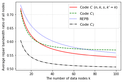
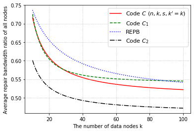
Let be the second piggybacking codes in [18] and be the codes in [19]. Fig. 8 shows the average repair bandwidth ratio of all nodes for codes , , REPB codes [15] and the proposed codes , where and . Note that the sub-packetization of REPB codes and is inexplicit and usually less than . In Fig. 8, we choose the lower bound of the repair bandwidth of REPB codes and . The sub-packetization of is .
The results in Fig. 8 demonstrate that the proposed codes have the lowest average repair bandwidth ratio of all nodes compared to the existing piggybacking codes, when the sub-packetization level is less than and . Note that the sub-packetization of our codes is , which is lower than that of .
V-B Codes VS Piggybacking Codes
Recall that OOP codes [16] have the lowest repair bandwidth for any single-node failure among the existing piggybacking codes when , where the sub-packetization of OOP codes is or , and the minimum value of average repair bandwidth ratio of all nodes is
| (12) |
In the following, we show that our codes have strictly less repair bandwidth than OOP codes and thus have less repair bandwidth than all the existing piggybacking codes when .
Lemma 10.
Let be the average repair bandwidth ratio of all nodes of . When , we have
Proof.
It is easy to see that the storage overhead of ranges from to . According to Lemma 10, our codes have strictly less repair bandwidth than all the existing piggybacking codes when , at a cost of slightly more storage overhead.
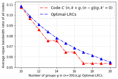
V-C The proposed Codes VS LRC
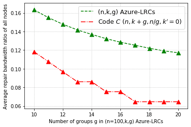
Next, we evaluate the repair bandwidth of our codes , codes , Azure-LRC [20] and optimal-LRC. According to Theorem 8, the repair bandwidth of our is strictly less than that of Azure-LRC [20]. Fig. 9 shows the average repair bandwidth ratio of all nodes for and Azure-LRC when the fault-tolerance is 8 and . The results demonstrate that have strictly less repair bandwidth than Azure-LRC. Moreover, our have less storage overhead than Azure-LRC. For example, have 44.92% less repair bandwidth and 6.16% less storage overhead than Azure-LRC when .
VI Conclusion
In this paper, we propose two new piggybacking coding designs. We propose one class of piggybacking codes based on the first design that are MDS codes, have lower repair bandwidth than the existing piggybacking codes when and the sub-packetization is . We also propose another piggybacking codes based on the second design that are non-MDS codes and have better tradeoff between storage overhead and repair bandwidth, compared with Azure-LRC and optimal-LRC for some parameters. One future work is to generalize the piggybacking coding design over codewords of more than two different MDS codes. Another future work is to obtain the condition of that can recover any failures.
References
- [1] I. S. Reed and G. Solomon, “Polynomial Codes over Certain Finite Fields,” Journal of the Society for Industrial & Applied Mathematics, vol. 8, no. 2, pp. 300–304, 1960.
- [2] D. Ford, F. Labelle, F. I. Popovici, M. Stokely, V.-A. Truong, L. Barroso, C. Grimes, and S. Quinlan, “Availability in Globally Distributed Storage Systems,” in Proc. of the 9th Usenix Symposium on Operating Systems Design and Implementation, 2010, pp. 1–7.
- [3] A. Dimakis, P. Godfrey, Y. Wu, M. Wainwright, and K. Ramchandran, “Network Coding for Distributed Storage Systems,” IEEE Trans. Information Theory, vol. 56, no. 9, pp. 4539–4551, Sep. 2010.
- [4] K. V. Rashmi, N. B. Shah, and P. V. Kumar, “Optimal Exact-Regenerating Codes for Distributed Storage at the MSR and MBR Points via a Product-Matrix Construction,” IEEE Trans. Information Theory, vol. 57, no. 8, pp. 5227–5239, August 2011.
- [5] I. Tamo, Z. Wang, and J. Bruck, “Zigzag Codes: MDS Array Codes with Optimal Rebuilding,” IEEE Trans. Information Theory, vol. 59, no. 3, pp. 1597–1616, May 2013.
- [6] H. Hou, K. W. Shum, M. Chen, and H. Li, “BASIC Codes: Low-Complexity Regenerating Codes for Distributed Storage Systems,” IEEE Trans. Information Theory, vol. 62, no. 6, pp. 3053–3069, 2016.
- [7] M. Ye and A. Barg, “Explicit Constructions of Optimal-Access MDS Codes with Nearly Optimal Sub-Packetization,” IEEE Trans. Information Theory, vol. 63, no. 10, pp. 6307–6317, 2017.
- [8] J. Li, X. Tang, and C. Tian, “A Generic Transformation to Enable Optimal Repair in MDS codes for Distributed Storage Systems,” IEEE Trans. Information Theory, vol. 64, no. 9, pp. 6257–6267, 2018.
- [9] S. B. Balaji and P. V. Kumar, “A tight lower bound on the sub- packetization level of optimal-access msr and mds codes,” in Proc. IEEE Int. Symp. Inf. Theory, 2018, pp. 2381–2385.
- [10] H. Hou, P. P. Lee, and Y. S. Han, “Multi-Layer Transformed MDS Codes with Optimal Repair Access and Low Sub-Packetization,” arXiv preprint arXiv:1907.08938, 2019.
- [11] H. Hou and P. P. Lee, “Binary MDS Array Codes with Optimal Repair,” IEEE Trans. Information Theory, vol. 66, no. 3, pp. 1405–1422, Mar. 2020.
- [12] K. V. Rashmi, N. B. Shah, D. Gu, H. Kuang, D. Borthakur, and K. Ramchandran, “A Hitchhiker’s Guide to Fast and Efficient Data Reconstruction in Erasure-Coded Data Centers,” in Proceedings of the 2014 ACM Conference on SIGCOMM, 2014, pp. 331–342.
- [13] K. V. Rashmi, N. B. Shah, and K. Ramchandran, “A Piggybacking Design Framework for Read-and Download-efficient Distributed Storage Codes,” IEEE Trans. Information Theory, vol. 63, no. 9, pp. 5802–5820, 2017.
- [14] B. Yang, X. Tang, and J. Li, “A Sytematic Piggybacking Design for Minimum Storage Regenerating Codes,” IEEE Trans. Information Theory, vol. 61, no. 11, pp. 5779–5786, 2014.
- [15] S. Yuan, Q. Huang, and Z. Wang, “A Repair-Efficient Coding for Distributed Storage Systems Under Piggybacking Framework,” IEEE Trans. Communications, vol. 66, no. 8, pp. 3245–3254, 2018.
- [16] G. Y. Li, X. Lin, and X. Tang, “An Efficient One-to-One Piggybacking Design for Distributed Storage Systems,” IEEE Trans. Communications, vol. 67, no. 12, pp. 8193–8205, 2019.
- [17] C. Shangguan and G. Ge, “A new piggybacking design for systematic mds storage codes,” Designs, Codes and Cryptography, 2016.
- [18] Z. Jiang, H. Hou, Y. S. Han, Z. Huang, B. Bai, and G. Zhang, “An efficient piggybacking design with lower repair bandwidth and lower sub-packetization,” in Proc. IEEE Int. Symp. Inf. Theory, 2021, pp. 2328–2333.
- [19] R. Sun, L. Zhang, and J. Liu, “A new piggybacking design with low repair bandwidth and complexity,” IEEE Communications Letters, vol. 25, no. 7, pp. 2099–2103, 2021.
- [20] C. Huang, H. Simitci, Y. Xu, A. Ogus, B. Calder, P. Gopalan, J. Li, and S. Yekhanin, “Erasure Coding in Windows Azure Storage,” in Usenix Conference on Technical Conference, 2012.
- [21] I. Tamo and A. Barg, “A Family of Optimal Locally Recoverable Codes,” IEEE Trans. Information Theory, vol. 60, no. 8, pp. 4661–4676, 2014.
- [22] N. B. Shah, K. Rashmi, P. V. Kumar, and K. Ramchandran, “Interference Alignment in Regenerating Codes for Distributed Storage: Necessity and Code Constructions,” IEEE Trans. Information Theory, vol. 58, no. 4, pp. 2134–2158, 2012.
- [23] M. Ye and A. Barg, “Explicit Constructions of High-Rate MDS Array Codes with Optimal Repair Bandwidth,” IEEE Trans. Information Theory, vol. 63, no. 4, pp. 2001–2014, 2017.
- [24] P. Corbett, B. English, A. Goel, T. Grcanac, S. Kleiman, J. Leong, and S. Sankar, “Row-Diagonal Parity for Double Disk Failure Correction,” in Proc. of the 3rd USENIX Conf. on File and Storage Technologies (FAST), 2004, pp. 1–14.
- [25] M. Blaum, J. Brady, J. Bruck, and J. Menon, “EVENODD: An Efficient Scheme for Tolerating Double Disk Failures in RAID Architectures,” IEEE Trans. Computers, vol. 44, no. 2, pp. 192–202, 1995.
- [26] H. Hou and Y. S. Han, “A New Construction and an Efficient Decoding Method for Rabin-Like Codes,” IEEE Trans. Communications, vol. 66, no. 2, pp. 521–533, 2018.
- [27] L. Xu and J. Bruck, “X-code: MDS Array Codes with Optimal Encoding,” IEEE Transactions on Information Theory, vol. 45, no. 1, pp. 272–276, 1999.
- [28] A. S. Rawat, I. Tamo, V. Guruswami, and K. Efremenko, “MDS Code Constructions with Small Sub-packetization and Near-optimal Repair Bandwidth,” IEEE Trans. Information Theory, vol. 64, no. 10, pp. 6506–6525, 2018.
- [29] L. Jie and X. Tang, “A Systematic Construction of MDS Codes with Small Sub-packetization Level and Near Optimal Repair Bandwidth,” IEEE Trans. Information Theory, vol. 67, no. 4, pp. 2162–2180, 2021.
- [30] H. Hou, Y. S. Han, K. W. Shum, and H. Li, “A Unified Form of EVENODD and RDP Codes and Their Efficient Decoding,” IEEE Trans. Communications, vol. 66, no. 11, pp. 5053–5066, 2018.
- [31] D. S. Papailiopoulos and A. G. Dimakis, “Locally Repairable Codes,” IEEE Trans. Information Theory, vol. 60, no. 10, pp. 5843–5855, 2014.
- [32] V. Guruswami, C. Xing, and C. Yuan, “How Long Can Optimal Locally Repairable Codes Be?” IEEE Trans. Information Theory, vol. 65, no. 6, pp. 3662–3670, 2019.
- [33] B. Chen, W. Fang, S. T. Xia, J. Hao, and F. W. Fu, “Improved Bounds and Singleton-Optimal Constructions of Locally Repairable Codes With Minimum Distance 5 and 6,” IEEE Trans. Information Theory, vol. 67, no. 1, pp. 217–231, 2020.
- [34] H. Cai, M. Y., M. Schwartz, and X. Tang, “On Optimal Locally Repairable Codes With Super-Linear Length,” IEEE Trans. Information Theory, vol. 66, no. 8, pp. 4853–4868, 2020.