A Computational and Experimental Analysis of Higher Order Modes in a Strongly Focusing Optical Cavity
Abstract
Optical cavities operating in the near-concentric regime are the fundamental tools to perform high precision experiments like cavity QED applications. A strong focusing regime unfortunately is prone to excite higher-order modes. Higher-order mode excitation is challenging to avoid for the realistic strong focusing cavities, and if these modes are closely spaced, overall cavity linewidth gets significantly broadened. In this study, a computational method alongside the experiment is provided for the optical mode decomposition into cavity eigenmodes with justified approximations. It is shown that it is possible to recreate the intensity and spectral profile of the cavity transmission, with the provided model. As a result, a more complete treatment of the realistic near-concentric cavities can be done.
I Introduction
Optical cavities are at the heart of photonics applications, including profound quantum and non-linear effects, high optical power, and precise control of atoms and molecules [1, 2, 3, 4, 5, 6, 7, 8, 9]. To acquire strong atom-photon coupling, high precision, and sensitivity demanded by such applications, detailed knowledge of the optical mode structure in the cavity is needed [10, 11]. In practice, higher-order modes can also be excited in the strong coupling regime, together with the target optical mode [12, 13].
To model modern cavity QED experiments in strong coupling conditions, it is necessary to determine the coupling efficiency of higher-order modes. Moreover, each higher-order mode is subject to different diffraction losses and mode matching efficiencies [14]. Hence, diffraction losses and reflectivity of the resonator mirrors should be considered for a realistic description of the mode structure of the cavity. A well-defined single mode for an optical cavity requires that the radius of curvatures of the resonator mirrors, placed at the nodes of the standing wave pattern, match that of the wavefront of the input optical mode. If the beam’s wavefront is not aligned perfectly with the radius of curvature of the resonator mirror, mode decomposition structure changes. In addition, the aberrations caused by the cavity mirror or the mode-matching optics perturb the system from the ideal situation and lead to excitation of the higher-order modes. This results in the cavity linewidth broadening of the cavity transmission, if the higher-order modes cannot be resolved [15, 16]. If the higher-order modes are closely spaced, broadening makes the resolution of the fundamental mode impossible. Hence, determination of the detailed mode structure and the linewidth broadening due to higher-order modes in realistic models of optical cavities, which is our objective here, is significant for the efficient implementation of photonics applications.
We construct an optical cavity experimentally in the strong focusing regime and apply a computational approach to calculate the cavity’s mode structure and the linewidth broadening due to the higher-order mode excitations observed in the experiment. Our approach allows for the determination of the change in the overall cavity linewidth due to the different minimum beam waists, reflectivities, and mirror apertures, which can be particularly significant for applications in the strongly focused optical cavity regime. The model offered in this paper allows us to study different parameters that are vital to the understanding of the near-concentric cavities. Furthermore, it can also be used to simulate all types of optical cavities with spherical mirrors for arbitrary incident optical mode with various phases, and it is the generalized version of the work given by Ref. [12] . In this work, the effect of each higher order mode is analyzed, rather than their combined behavior which can be found in Ref. [12, 13]. Effects of different parameters like coupling efficiencies, diffraction losses, reflectivities, or beam waist sizes can be understood thoroughly with the help of the mode decomposition analysis presented in this work. Arbitrary shape optical modes can be studied further with the given model by changing the phase parameter in the incident mode definition. Investigating near-concentric cavity parameters in terms of each mode contributes to the complete understanding of these devices.
The rest of the paper is organized as follows. Sec. II describes our experimental optical cavity setup. Sec. III introduces the computational methods we use to assess the significance of higher-order modes in the optical cavity. Sec. IV presents the experimental and computational results. We conclude in Sec. V.
II Physical System
Physical system consists of two spherical plano-concave mirrors whose geometrical and optical features are exactly the same. Mirror sizes (a), radius of curvatures (ROC) and thicknesses (t) are taken as 6.35 mm, 50 mm and 1.5 mm, respectively. For the both simulation and the experiment, 780 nm light is used. Reflectivities are 0.9798 for the both mirrors. In the study, we use near-concentric cavity whose cavity length is nearly mm. Physical system is studied experimentally and computationally. Simple diagram for the experiment is seen in Fig. 1.
III Methods
Optical cavity modes can be described by different sets of polynomials. One of the widely used modes are Laguerre-Gaussian modes which can be written as the following [17],
| (1) |
where are generalized Laguerre polynomials, is mode waist at the position z, p is the radial index, l is the azimuthal index, R(z) is the radius of curvature of the wavefront at the position z, is the Gouy phase which can be written in terms of the Rayleigh length, and are the normalization coefficients. We consider a cylindrically symmetric optical cavity, described by modes and driven by an optical mode taken to be in the form of , which can be written as [12, 13],
| (2) |
In the model, optical mode wavefront is taken as spherical, whose radius of curvature is exactly equal to the radius of curvature of the cavity mirrors. Simulation parameters are the same as those used in the experimental study, described in Sec. II. In order to find the beam waist at the mirror and the cavity length, initially half cavity length is calculated for each minimum beam waist value by the following equation,
| (3) |
by finding the z value whose radius of curvature is exactly equal to the radius of curvature of the mirror. This z value gives the position of the mirror, which is substituted in the Eq. (4) to find the beam waist at the mirror,
| (4) |
It is assumed that the input beam has a perfect spherical wavefront without any azimuthal deviation, and a phase difference is introduced in the radial direction. We employ the paraxial approximation and calculated the phase of the optical mode by the standard ray-tracing methods [12, 13]. Coupling strength of the optical drive to a cavity mode is characterized by the mode overlap function,
| (5) |
It is an intuitive measure of the injected power distribution inside the cavity resonator and is the normalized integral version of the Eq. (5). Spatial profile of the cavity is given in Fig. 2. Spatial profile of the overlap function for the input mode and the set of cavity modes is seen in Fig. 2. The total overlap function is calculated for and and their combined effect is shown in Fig. 2. The total overlap function changes to weighted summation over the modes in calculating optical properties, such as transmission of the cavity and power distribution inside the cavity. Corresponding heat map and the camera picture obtained from the experiment is shown in Fig. 3. As can be seen from the graph, heat map and the camera picture have a good matching profile.
In order to calculate the cavity transmission, the amount of power left in the cavity after one round trip should be taken into account and it is given by which are calculated as [12],
| (6) |
where a is the mirror aperture. The coefficient of finesse is defined [18],
| (7) |
where is the reflection coefficient, which should be calculated separately for each cavity eigenmode by taking the mirror reflectivities and diffraction losses into account using,
| (8) |
Transmission of each higher order mode can be written as . While calculating the power inside the cavity and the power in each higher order mode, following equation is used [19],
| (9) |
where is the phase difference between the interfering wavefronts which is in this case equal to . With the coefficient of finesse , finesse can be written as [18],
| (10) |
IV Results and Discussion
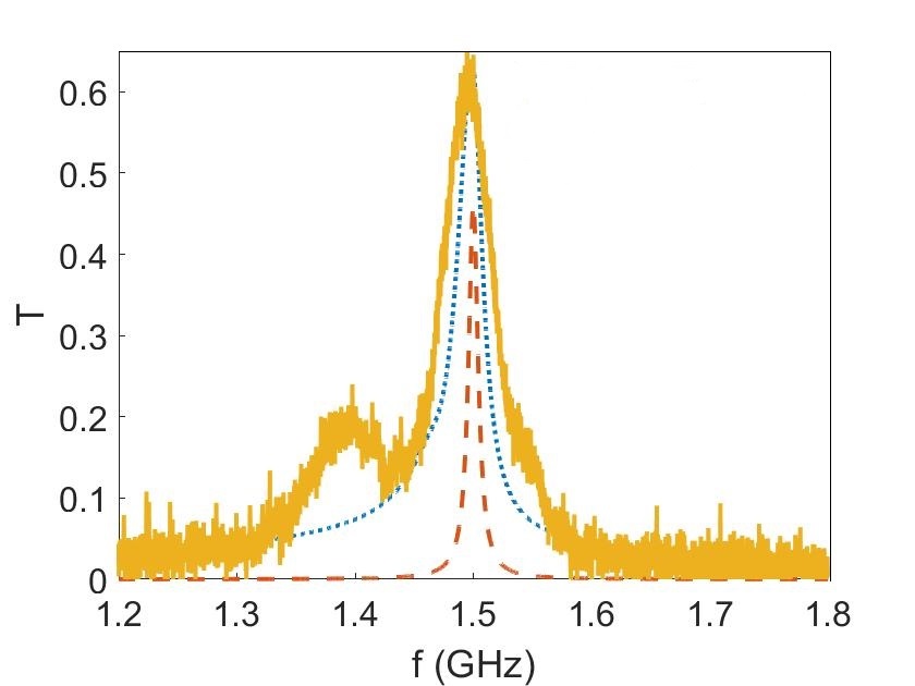
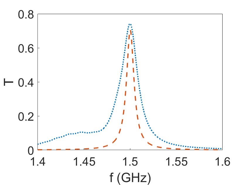
Cavity in the near-concentric regime is experimentally realized as described in the Sec. II, whose transmission graph is given in Fig. 4. On the same graph, fundamental cavity eigenmode transmission and the overall field transmission can be seen. From the experimental data, shown with the yellow solid line, it is seen that the overall field does not only include the fundamental mode, but it is broadened due to the higher order mode excitations. Fig. 3 and Fig. 4 prove that the model matches with the experimental scenario and similar patterns can be found in Ref. [12] since the same type of optical cavities are used.
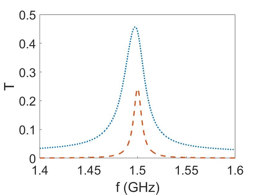
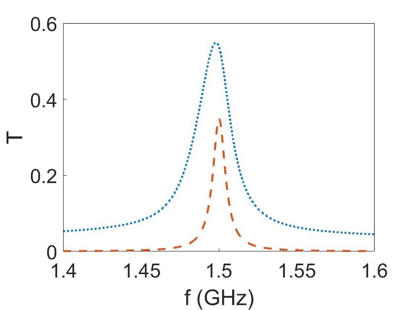
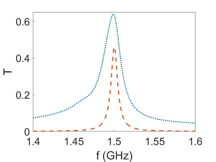
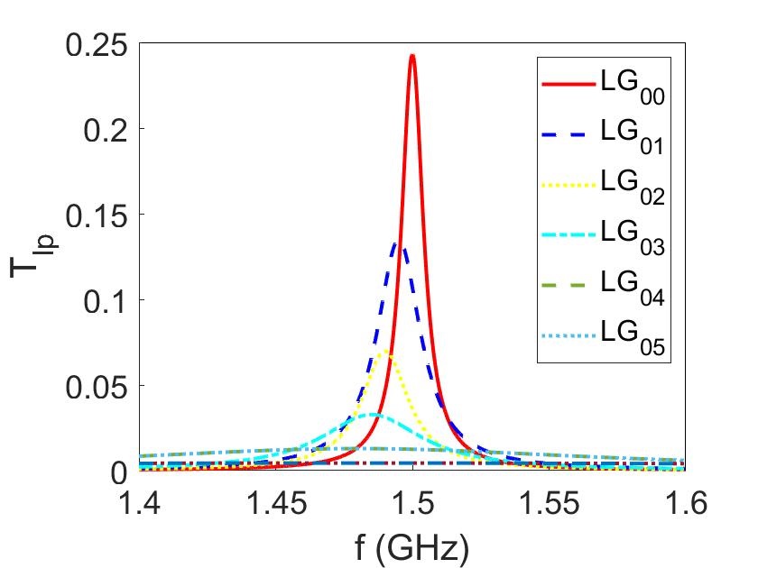
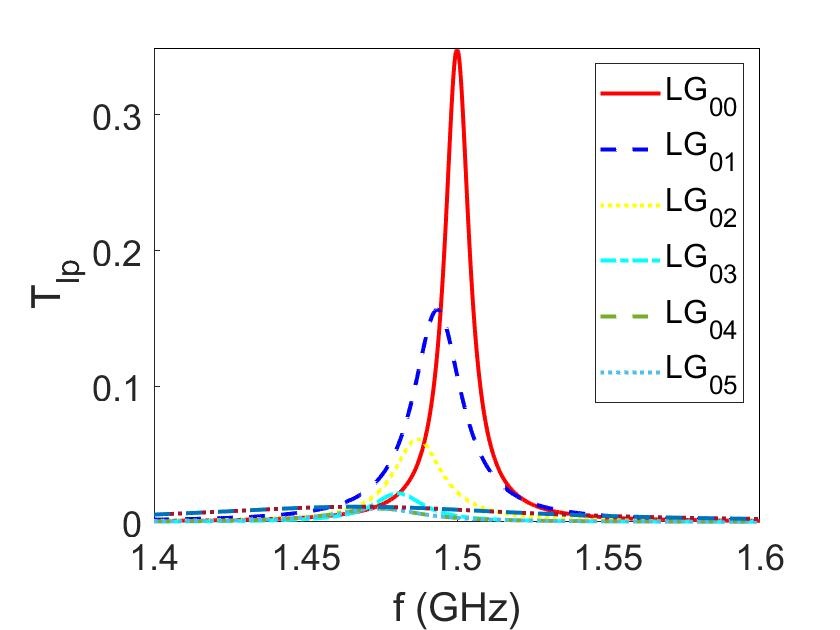
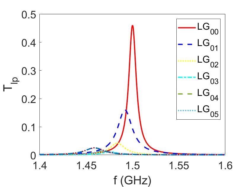
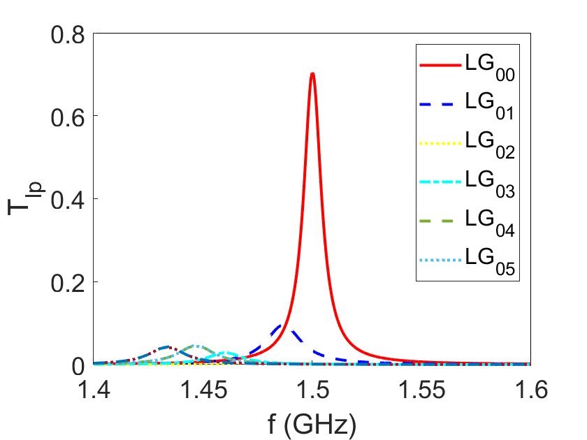
The linewidth broadening effect becomes more significant in the strong focusing regime, where beam waist at the mirror () is much larger than the beam waist at the focus, , as shown in Fig. 5. In addition to Ref. [12], which examines the case of m minimum beam waist value, and m cases are examined to demonstrate the effect of different minimum beam waists on the cavity linewidth. Transmission coefficients for individual cavity modes , shown in Fig. 6, are closely spaced, being impossible to resolve altogether.
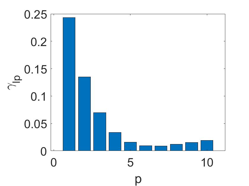
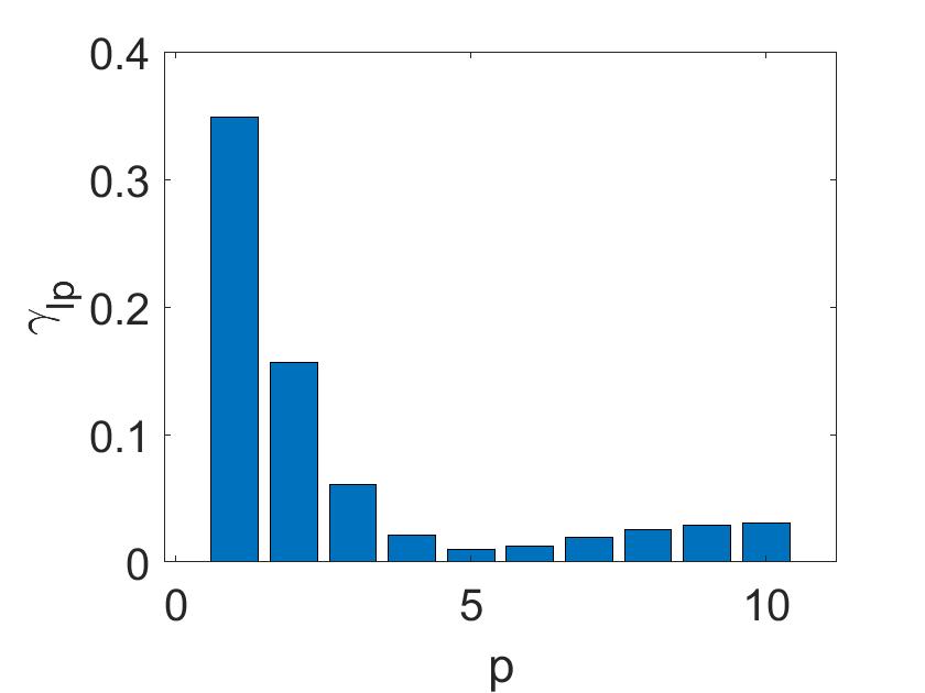
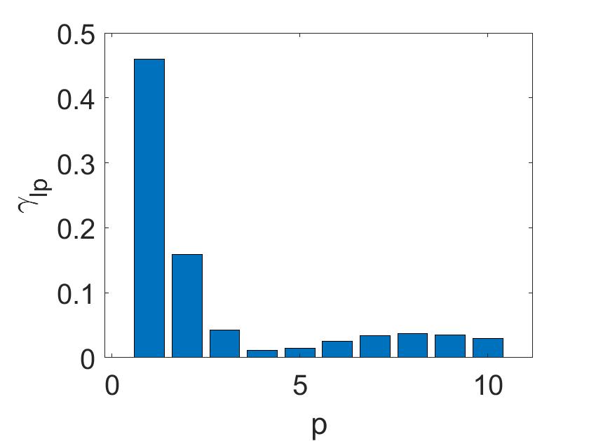

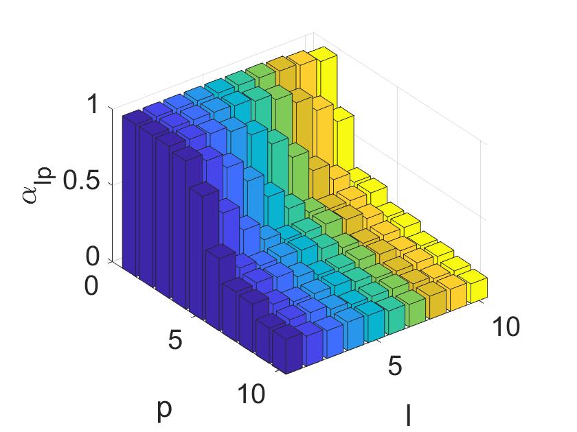
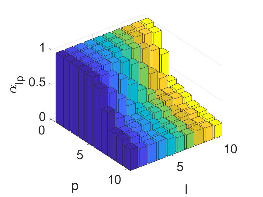
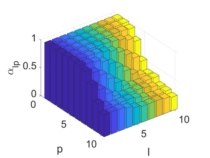
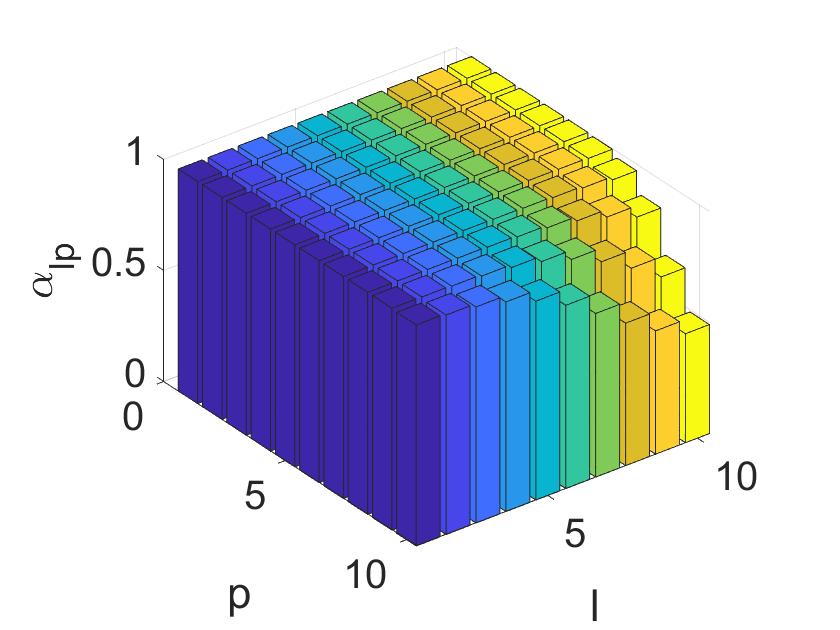
The coupling efficiencies () and the power left inside the cavity after one round trip () for each higher-order modes are seen in Fig. 7 and Fig. 8, respectively. Coupling efficiencies become minmum after which means higher-order mode excitations are remarkable in the first several cavity eigenmodes. As the focusing strength decreases, where sizes of the minimum beam waist and the beam waist at the mirror become comparable, coupling efficiency in the higher-order modes decrease.
Diffraction losses become dominant for the higher-order modes and it is the main reason for the power loss for those cavity eigenmodes. Due to the finite size of the mirrors, diffraction losses are inevitable and higher-order modes suffer from diffraction losses due to their larger size. The effect of the diffraction losses for the near-concentric cavity can be seen in Fig. 8. It is seen that if the minimum beam waist is larger, higher-order modes are less affected. The reason for this is, the beam waist at the mirror decreases with the increasing minimum beam waist which results in lower focusing power. With the decreasing beam waist at the mirror, one can observe that the effect of the diffraction losses becomes less important, and as a result, the broadening effect becomes manageable.
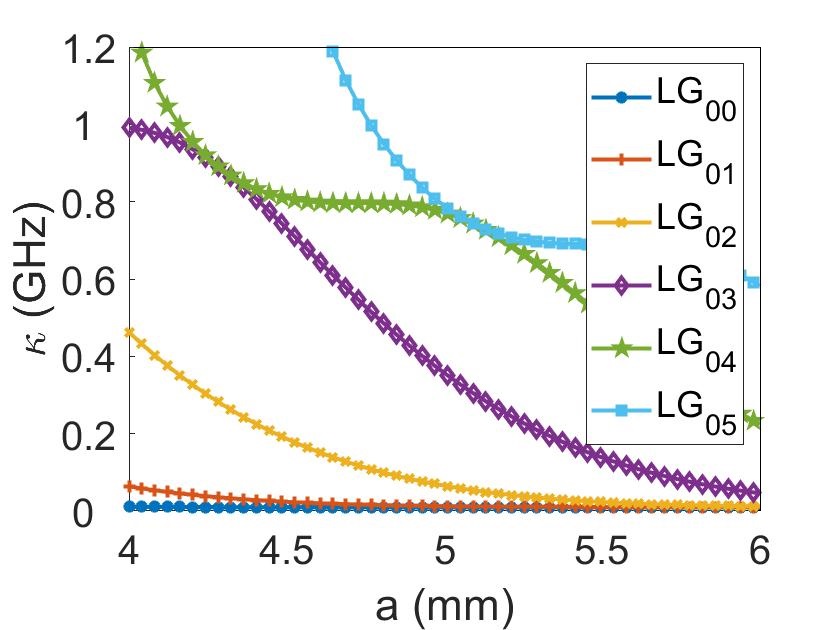
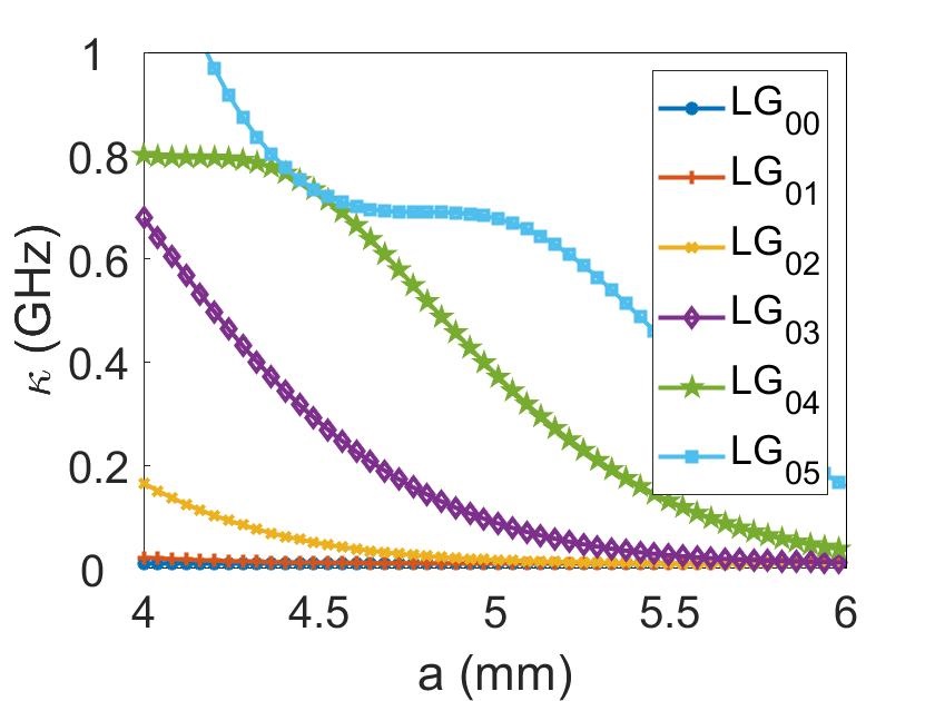
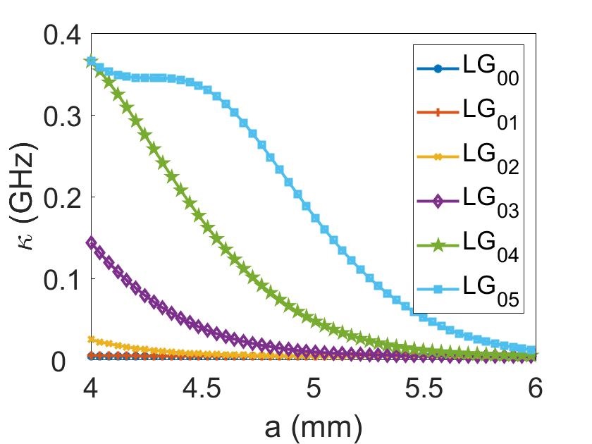
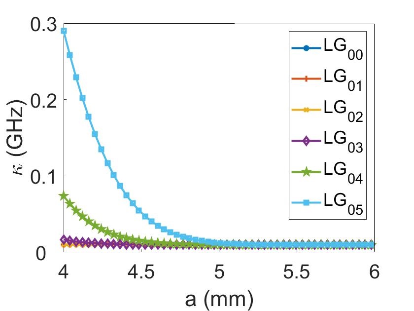
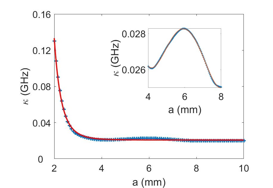
The effect of the mirror apertures on the linewidth of each higher-order mode can be seen in Fig. 9. As aperture size increases, linewidth for each cavity eigenmode decreases and this behavior does not change for different focusing strengths. Changes in the focusing strength can easily be seen in the different minimum beam waist. When each higher-order mode effect is taken into account, overall cavity linewidth behavior can be calculated. The overall behavior of the cavity when aperture size is increasing is seen in Fig. 10. Aperture size ranges of 2-10 mm and 4-8 mm are demonstrated in Fig. 10.
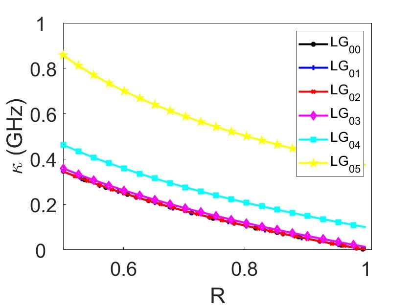
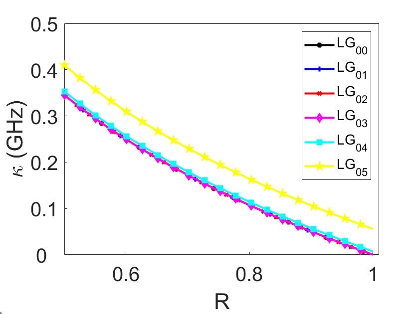
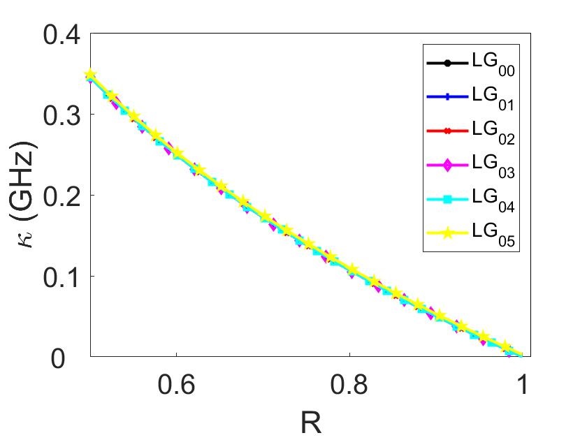
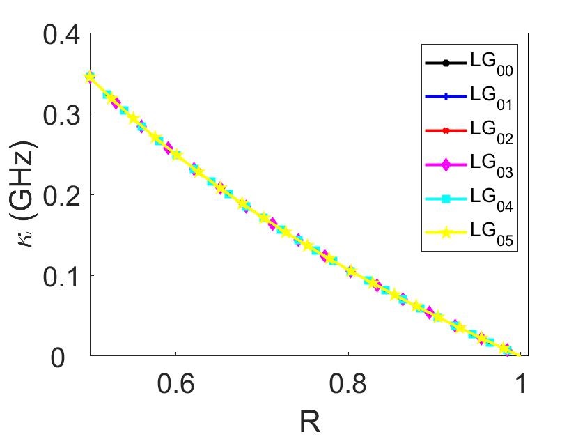
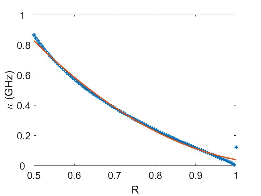
One of the other most important factors that contribute to the linewidth of the cavity is the reflectivity of the mirrors which is seen in Fig. 11. While calculating the linewidth, not only the reflectivity of the mirrors are taken into account but also reflectivity affected by the diffraction losses are calculated which is . It can be seen that the behavior is the same for the first few cavity eigenmodes in Fig. 11. The first few cavity eigenmodes have comparable sizes, while higher-order modes have larger sizes and suffering from diffraction losses. With diffraction losses taken into account, effective reflectivity changes for higher-order cavity eigenmodes, resulting in broadened linewidth for these modes. Overall cavity linewidth changes with the mirror reflectivity can be seen in Fig. 12. As expected, linewidth decreases with increasing reflectivity, whose behavior can be described by second-order polynomial fit.
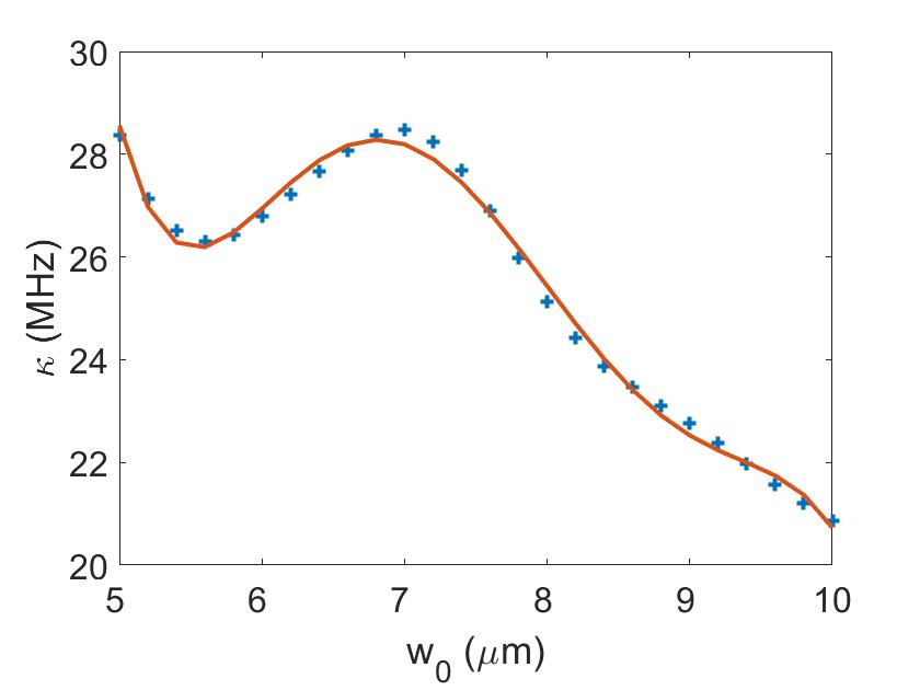
Focusing strength is inversely proportional to the minimum beam waist of the cavity. A bigger minimum beam waist means lower focusing strength which results in a smaller beam waist at the mirror. When the beam waist at the mirror is small, the losses due to the finite aperture size of the mirrors does not affect each higher-order mode differently and the linewidth broadening effect is negligible. Another reason is the validity of the paraxial approximation in that regime. Paraxial approximation holds when , which means low focusing strength. The linewidth broadening effect can be seen for different minimum beam waist values which mean different focusing strengths in Fig. 13. As the focusing strength decreases, linewidth also decreases due to the decreasing higher-order mode excitation. For different minimum beam waist values, half cavity lengths and beam waist at the mirror values are calculated and overall cavity calculations are done according to those values in Fig. 13.
V Conclusion
In summary, we presented a numerical and experimental investigation of the effects of the higher-order modes in an optical cavity in the strong focusing regime. Different than earlier works [12, 13], our results include the effects of the different parameters like reflectivities, numerical apertures, and beam waist sizes for each higher-order mode. Effective and complete treatment of the near-concentric cavities can be done with the help of the mode decomposition analysis applied for those features. The excitation of higher order modes, due to diffraction loss or any other imperfect mode-matching mechanism, can result in the broadening of the cavity transmission peak effectively. This effect is difficult to distinguish experimentally and the proposed method allows the realization of the effects of the higher order modes. The optical mode decomposition into the cavity eigenmodes provides means to simulate the intensity and transmission spectrum distributions of any cavity. The assumptions of the model seem to be justified by a comparison of experimental results with the simulated ones in the near-concentric regime. The choice of near-concentric is due to the fact that the effect of linewidth broadening is more prominent in this regime. The presented model is expected to guide the experimentalists in the preparation of cavities for avoiding misinterpretations of the observed cavity outputs in the experiment of interest. Our results can illuminate the way of designing optical cavities for strong coupling cavity QED applications, demanded by modern quantum technologies.
Acknowledgements.
This work was supported by the Scientific and Technological Research Council of Turkey (TUBITAK) with project number 119F200.References
- Dutra [2005] S. M. Dutra, Cavity quantum electrodynamics: the strange theory of light in a box (John Wiley & Sons, 2005).
- Thompson et al. [1992] R. Thompson, G. Rempe, and H. Kimble, Observation of normal-mode splitting for an atom in an optical cavity, Physical review letters 68, 1132 (1992).
- Hood et al. [1998] C. Hood, M. Chapman, T. Lynn, and H. Kimble, Real-time cavity qed with single atoms, Physical review letters 80, 4157 (1998).
- Puppe et al. [2004] T. Puppe, P. Maunz, T. Fischer, P. W. Pinkse, and G. Rempe, Single-atom trajectories in higher-order transverse modes of a high-finesse optical cavity, Physica Scripta 2004, 7 (2004).
- Reiserer and Rempe [2015] A. Reiserer and G. Rempe, Cavity-based quantum networks with single atoms and optical photons, Reviews of Modern Physics 87, 1379 (2015).
- Brennecke et al. [2007] F. Brennecke, T. Donner, S. Ritter, T. Bourdel, M. Köhl, and T. Esslinger, Cavity qed with a bose–einstein condensate, nature 450, 268 (2007).
- Clifford et al. [1998] M. Clifford, J. Arlt, J. Courtial, and K. Dholakia, High-order laguerre–gaussian laser modes for studies of cold atoms, Optics Communications 156, 300 (1998).
- Nguyen et al. [2017] C. H. Nguyen, A. N. Utama, N. Lewty, K. Durak, G. Maslennikov, S. Straupe, M. Steiner, and C. Kurtsiefer, Single atoms coupled to a near-concentric cavity, Physical Review A 96, 031802 (2017).
- Nguyen et al. [2018] C. H. Nguyen, A. N. Utama, N. Lewty, and C. Kurtsiefer, Operating a near-concentric cavity at the last stable resonance, Physical Review A 98, 063833 (2018).
- Bond et al. [2011] C. Bond, P. Fulda, L. Carbone, K. Kokeyama, and A. Freise, Higher order laguerre-gauss mode degeneracy in realistic, high finesse cavities, Physical Review D 84, 102002 (2011).
- Utama et al. [2021] A. N. Utama, C. H. Chow, C. H. Nguyen, and C. Kurtsiefer, Coupling light to higher order transverse modes of a near-concentric optical cavity, Optics Express 29, 8130 (2021).
- Durak et al. [2014] K. Durak, C. H. Nguyen, V. Leong, S. Straupe, and C. Kurtsiefer, Diffraction-limited fabry–perot cavity in the near concentric regime, New Journal of Physics 16, 103002 (2014).
- Kleckner et al. [2010] D. Kleckner, W. T. Irvine, S. S. Oemrawsingh, and D. Bouwmeester, Diffraction-limited high-finesse optical cavities, Physical Review A 81, 043814 (2010).
- Benedikter et al. [2015] J. Benedikter, T. Hümmer, M. Mader, B. Schlederer, J. Reichel, T. W. Hänsch, and D. Hunger, Transverse-mode coupling and diffraction loss in tunable fabry–pérot microcavities, New Journal of Physics 17, 053051 (2015).
- Hood et al. [2001] C. J. Hood, H. Kimble, and J. Ye, Characterization of high-finesse mirrors: Loss, phase shifts, and mode structure in an optical cavity, Physical Review A 64, 033804 (2001).
- Jaffe et al. [2021] M. Jaffe, L. Palm, C. Baum, L. Taneja, and J. Simon, Aberrated optical cavities, arXiv preprint arXiv:2105.05235 (2021).
- Siegman [1986] A. E. Siegman, Lasers (University Science Books, 1986).
- Yariv and Yeh [2007] A. Yariv and P. Yeh, Photonics: optical electronics in modern communications (Oxford University Press, 2007).
- Lipson et al. [2010] A. Lipson, S. G. Lipson, and H. Lipson, Optical physics (Cambridge University Press, 2010).