Generation of S-shaped photonic hooks from microcylinders with engineered surface patches
Chu Xu1,2, Fen Tang1,2, Qingqing Shang1,2, Yao Fan2, Jiaji Li2, Songlin Yang3, Dong Wang1, Sorin Melinte4, Chao Zuo2, Zengbo Wang5,6, Ran Ye1,2*
1 School of Computer and Electronic Information, Nanjing Normal University, Nanjing 210023, China
2 Smart Computational Imaging Laboratory (SCILab), School of Electronic and Optical Engineering, Nanjing University of Science and Technology, Nanjing 210094, China
3 Advanced Photonics Center, Southeast University, Nanjing 210096, China
4 Institute of Information and Communication Technologies, Electronics and Applied Mathematics, Université Catholique de Louvain, 1348 Louvain-la-Neuve, Belgium
5 School of Computer Science and Electronic Engineering, Bangor University, Bangor LL57 1UT, UK
6 z.wang@bangor.ac.uk
*ran.ye@njnu.edu.cn
ABSTRACT:
Photonic hooks (PHs) are non-evanescent light beams with a highly concentrated curved optical fields. Since their discovery, PHs always have one single inflection point and thus have a hook-like structure. In this work, a new type of PHs with two inflection points and S-shaped structures (S-PHs) were reported for the first time. We theoretically studied the effects of various physical parameters on the generation of S-PHs. Furthermore, we showed that decorating particles with multiple patches can significantly enhance the curvature and length of the S-PHs. The S-PHs may have potential applications in super-resolution imaging, sub-wavelength micromachining, particle and cell manipulation, etc.
1 Introduction
Photonic nanojets (PJs) are high-intensity light waves with a subwavelength beam waist generated at the shadow side of illuminated dielectric particles [1], which have promising applications in various fields such as micromaching [2], super-resolution imaging [3, 4, 5, 6], etc. In recent years, a great effort has been put into particle designing to generate PJs with new features [7, 8]. In 2015, Minin et al. theoretically discovered a new type of PJs with curved optical fields [9]. They called them photonic hooks (PHs). PHs was later experimentally proved at terahertz frequency [10], and then at optical frequency [11]. PHs have potential applications in various fields, such as nanoparticle and cell manipulation [12, 8] and super-resolution microscopy [13]. In 2021, Shang et al. reported a contrast-enhanced super-resolution imaging technique using patchy microspheres [13]. The patchy microspheres convert incident light into a PH and induce a near-field asymmetric illumination condition. Asymmetric illumination is a common technique in computational microscopic imaging, which can enhance the contrast of objects [14]. Minin et al. also reported a PH-based terahertz microscopy technique [15].
When light waves pass through a dielectric particle whose shape or refractive index distribution is asymmetrical to the propagation direction of light, the difference in phase velocities and the interference of light waves lead to a curved high-intensity focus, i.e., a PH [16]. Illuminating geometrically asymmetric dielectric particles, such as dielectric trapezoids [16, 10] and glass cubes [17] embedded dielectric cylinders, with plane waves is a common way to generate PHs. Particles with an anisotropic refractive index distribution, such as Janus particles [18, 19], are also suitable for the generation of PHs. In addition, PHs can be generated by partial or nonuniform illumination of symmetric and homogeneous particles [11, 20], or by using dielectric particles partially covered with opaque films [21]. For example, Tang et al. used 1 - 35 m diameter patchy microcylinders to generate PHs. Half of the cylinder surface is covered with silver films, and PHs with a bending angle of 28.4∘ can be generated under plane wave illumination [21].
However, the aforementioned methods can only generate PHs with one inflection point. In this work, we show that a new type of PHs with two inflection points, S-shaped PHs (S-PHs), can be generated using patchy particles. To the best of our knowledge, it is the first time that S-shaped PHs are reported. Numerical simulations based on the finite-difference-time-domain (FDTD) method were performed to investigate the characteristics of the S-PHs. By changing the background refractive index, particle diameters and the position and coverage ratio of patches, the curvature, maximum intensity and the hot spot position of S-PHs can be effectively tuned. Moreover, the curvature of S-PHs can be further significantly enhanced using patchy particles with multiple patches.
2 Results and discussion
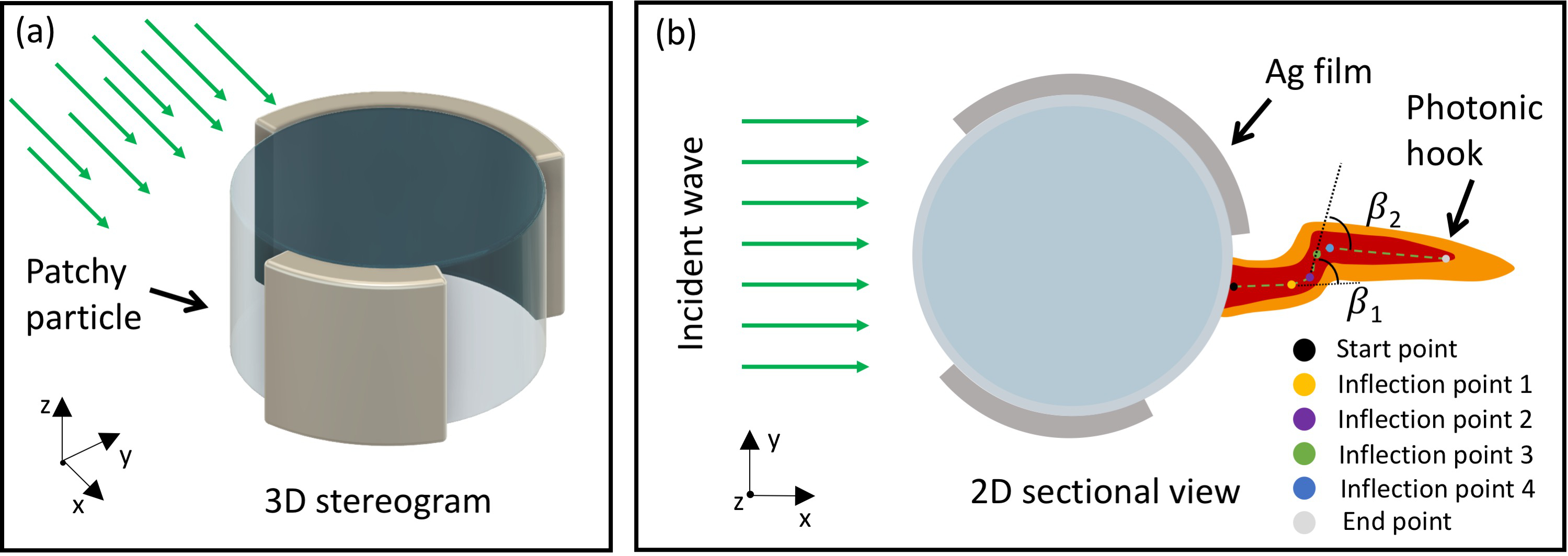
Figures 1(a), (b) are the schematic drawings of the 3D stereogram and 2D sectional view of the investigated model. A dielectric microcylinder was created for two-dimensional simulation with the FDTD method using Lumerical FDTD solutions. The surface of the cylinder is partially covered with 100 nm-thick Ag films. The center of the microcylinder is always located at the X = 0 m, Y = 0 m, and the profiles of the microcylinder as well as the scale bars are given in the following images. As shown in Figure 1(b), an intense focusing of light will occur on the shadow side of the cylinder when a P-polarized monochromatic plane wave ( = 550 nm) propagating parallelly to the X axis passes through the cylinder. In this study, the microcylinder has a constant RI of 1.90, the same as the refractive index of BaTiO3, which is a high-index dielectric material widely used in microsphere-assisted super-resolution imaging [5, 2, 13]. The diameter of the cylinder changes between 1 - 5 m and the RI of the background changes between 1.00 - 1.52. For the entire computational domain, non-uniform meshes with RI-dependent element size were used and all of them are smaller than /30.
As shown in Figure 1(b), a typical S-PH starts out with an approximately smooth midline. The midline bends upwards when meeting the S-shaped curve and then becomes stable. After a certain distance, the midline bends downwards to leave the S-shaped curve and then becomes smooth again until reaching the end point of the S-PH. The structure of a S-shaped photonic hook can be approximately defined by the start point (SP), the four inflection points (IP1, IP2, IP3 and IP4) and the end point (EP) of the photonic hook. The inflection points are the points at which the curvature state of the midline changes [22]. The end point in this study is defined as the point on the middle line of the photonic hook with an intensity enhancement factor of Imax/e [11, 23]. The Imax is the largest enhancement formed at the shadow side of the patchy microcylinder. Based on these points, the curvature of the S-shaped photonic hooks can be defined by the bending angle and . is the angle between the two lines respectively connecting the SP with the IP1, and the IP2 with the IP3. is the angle between the two lines respectively connecting the IP2 with the IP3, and the IP4 with the EP.
3 Results and Discussion
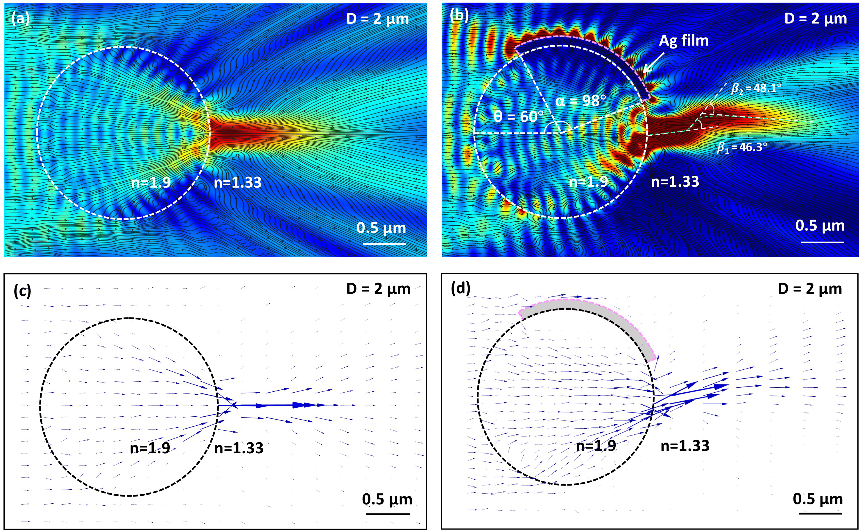
First, we compared the optical fields of 2 m-diameter pristine and patchy microcylinders under plane wave illumination. The background medium has a RI of n=1.33. As shown in Figure 2(a), the incident light passing through the pristine cylinder forms a conventional PNJ on the shadow side of the cylinder. The generated PNJ has a symmetric E distribution with the midline of the PNJ as the center of symmetry. On the contrary, as for the patchy microcylinder shown in Figure 2(b), the upper part of the incident light is blocked by the Ag film on the top surface of the cylinder. The rotation and opening angle of the film is =60∘ and =98∘, respectively. We find that a curved light beam with a S-shaped structure, i.e., a S-PH, with bending angles of =46.3∘ and =48.1∘ is formed at the shadow side of the cylinder.
As reported in the previous work [18, 23], the formation mechanism of PNJs and PHs can be analyzed using the time-averaged Poynting vector. In this work, the Poynting vector (blue conical arrows) of the optical field formed by pristine and patchy cylinders under plane wave illumination is simulated with the FDTD method [Figures 2(c), (d)], and the corresponding field-lines of the Poynting vector distribution are shown as the black lines in Figures 2(a) and (b). As shown in Figure 2(c), the spatial distribution of the Poynting vector inside and near the pristine cylinder is symmetric to the midline of the PNJ [Figure 2(c)]. Because the length of the conical arrows is proportional to the value of energy flux, the area containing longer arrows indicates a higher energy flux in that area. We can see that the energy flow corresponding to the pristine cylinder’s optical field is focused into a classical PNJ at the shadow side of the cylinder [Figure 2(c)]. However, as for patchy cylinders, part of the incident light is reflected backwards to the space by the Ag film, which breaks the symmetry of illumination and makes the energy flow inside the microcylinder unbalanced. This asymmetric flow of energy is then focused into a curved beam after leaving the patchy cylinder, as shown in Figures 2(b),(d).
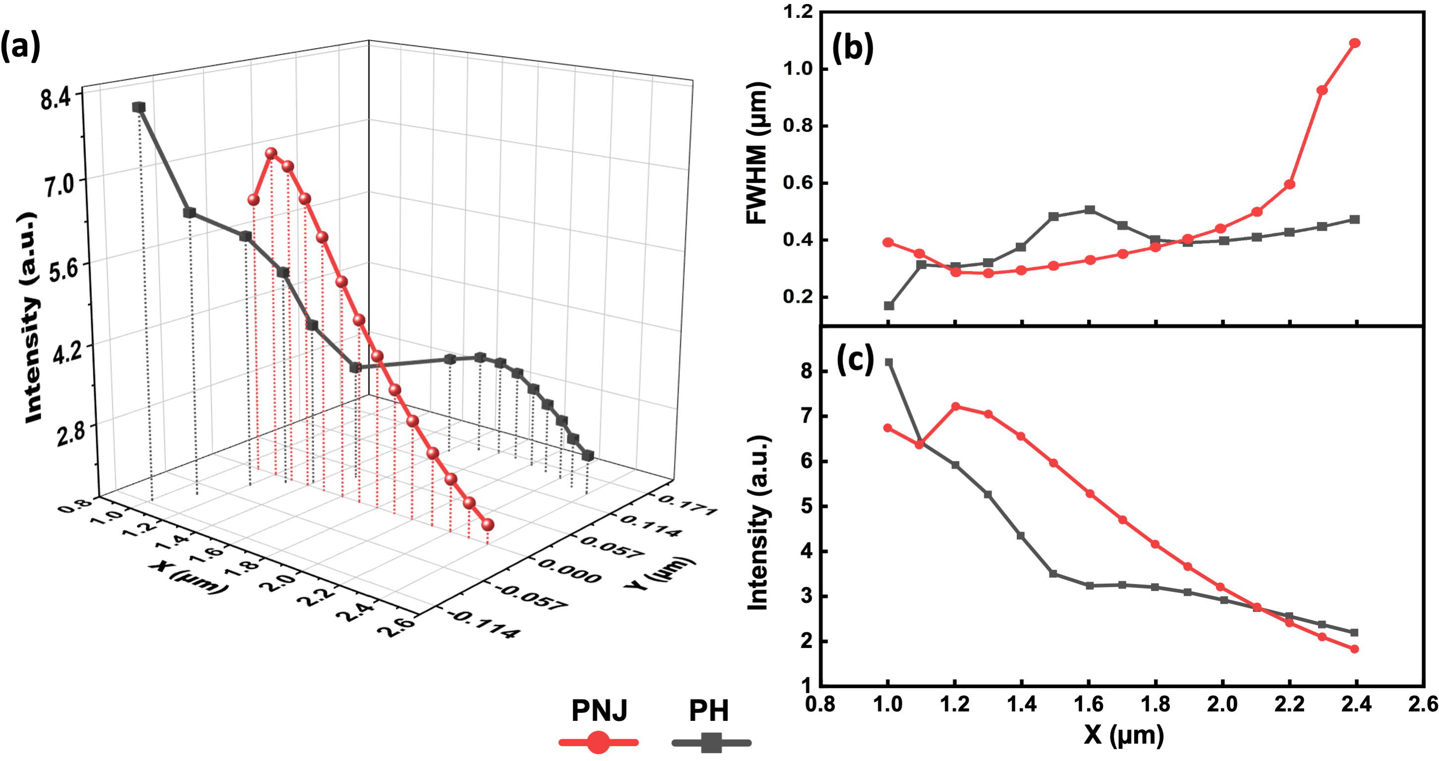
Figure 3(a) is the 3D trajectory of the Imax points of the PNJ [Figure 2(a)] and the S-PH [Figure 2(b)] obtained by slicing along X-axis in the range of X = 1 m to X = 2.4 m. Due to the symmetric nature of the PNJ, the optical field of the PNJ has the strongest intensity at its center at Y = 0 m. The Imax point of the photonic hook, on the other hand, has a S-shaped profile and a shift in the Y-axis. Figure 3(b) shows the FWHM of the intensity profiles of the PNJ and S-PH at different x-coordinates. The FWHM at the edge of the microcylinders (X = 1.0 m) is 0.17 m (0.31 ) and 0.39 m (0.71 ) for the S-PH and PNJ, respectively. After the light propagating another 0.2 m along the X-axis, the FWHM of the PNJ decreases to 0.29 m (0.53 ) and the light reaches the focal point of the cylinder. The S-PH has a slightly larger FWHM (0.56 ) at X = 1.2 m, and its beam waist continues to increase with the propagation distance of light. After a propagation distance of 1 m, the S-PH shows a significantly narrower beam waist than the PNJ, and the FWMH of the S-PH (0.85 ) is 43% of the PNJ (1.98 ) at X = 2.4 m. The property that the S-PH can retain a subwavelength FWHM at a longer propagation distance could be beneficial to the applications of particle manipulation and microfabrication. Figure 3(c) shows the variation of peak intensity of the PNJ (red line) and the S-PH (black line) along the X-axis. The S-PH shows a better intensity enhancement performance as the Imax of the S-PH and PNJ is 8.20 and 7.22, respectively. The S-PH also have a higher intensity at propagation distance longer than 4 . The peak intensity obtained at X = 2.4 m is 2.19 for the S-PH and 1.83 for the PNJ, respectively.
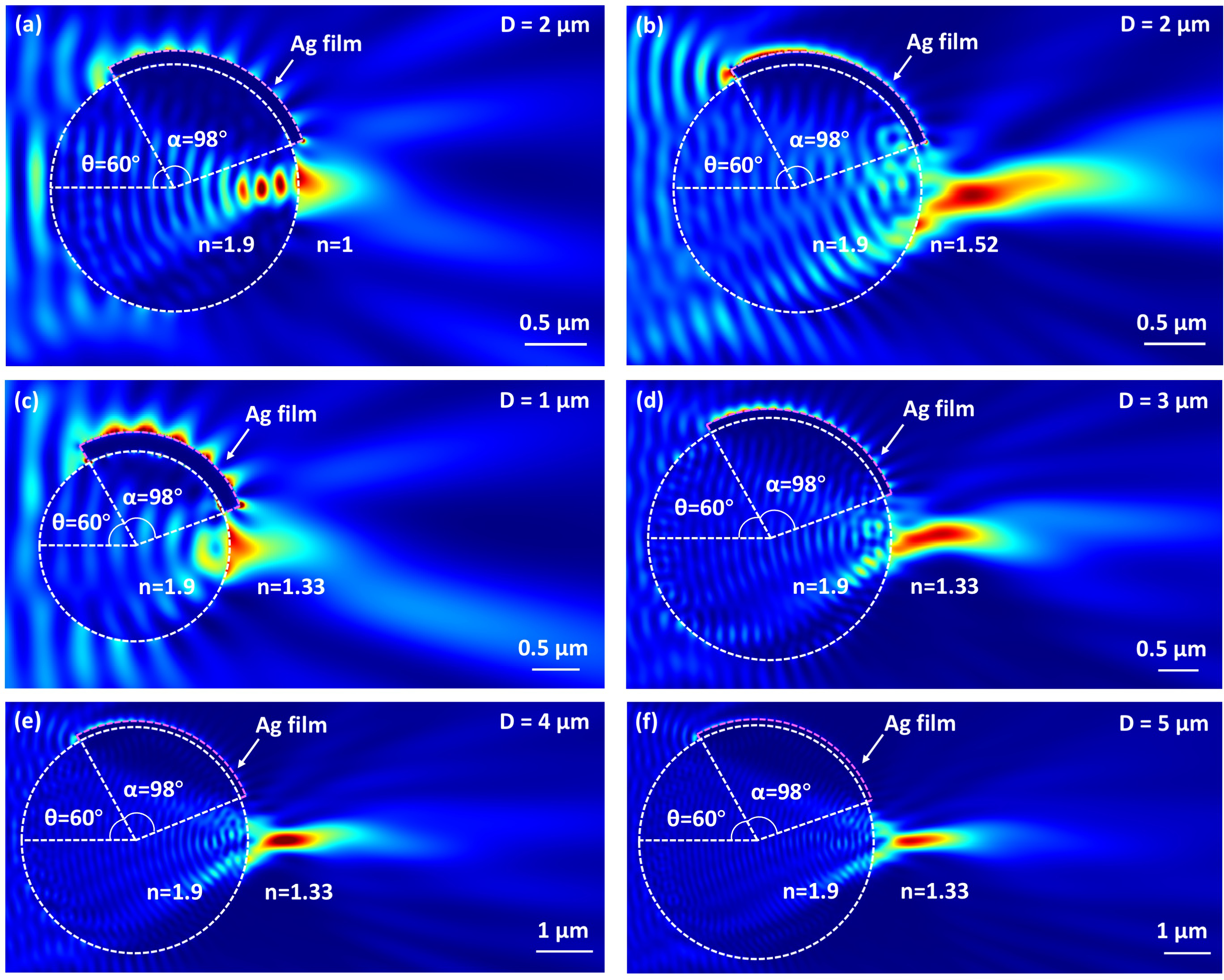
As shown in Figures 4(a),(b), the influence of background RI on the characteristics of obtained PHs was studied by changing the background RI to n=1.00 [Figure 4(a)] and n=1.52 [Figure 4(b)]. The particle diameter was kept constant at 2 m. The rotation angle and the opening angle of the Ag films are 60∘ and 98∘, respectively. As shown in Figure 4(a), when the background RI is 1.0, the light entering the microcylinder is focused to the edge of the cylinder. A higher RI contrast between the particle and the background leads to a stronger bending ability. The Imax is at X = 1.00 m, Y = 0.09 m with a value of 5.78. The intensity enhancement decreases to Imax/e after light propagates another 0.49 m along the X axis. We cannot observe a S-shaped structure between the SP and EP in the formed photonic hook. As shown in Figure 4(b), the focal length increases when the background RI is increased to n=1.52. The patchy particle forms a bended jet-like optical field with a small degree of curvature. The beam has the strongest intensity (Imax=5.39) at X=1.40 m, Y=-0.06 m and reaches its EP at X=2.75 m, Y=0.03 m. We found that the patchy microcylinder generates S-shaped PHs with a better quality in water [Figure 2(b)]. As water is a commonly used biocompatible material, studying PHs in water is important for the practical applications of such curved beams. We will focus on the generation of S-PHs in water in the following studies.
The influence of particle diameter on the S-PHs is also investigated in this study. As shown in Figures 4(c)-(f), the Imax position moves further away from the cylinder when the particle diameter increases from 1 m to 5 m. Larger particles also have a higher Imax value because they can focus more energy into the hot spot. S-PHs only can be generated from the 4 m-diameter patchy cylinder with a small curvature of =13.8∘, =14.6∘, which is much less curved than the S-PHs from the 2 m-diameter microcylinder [Figure 2(b)].
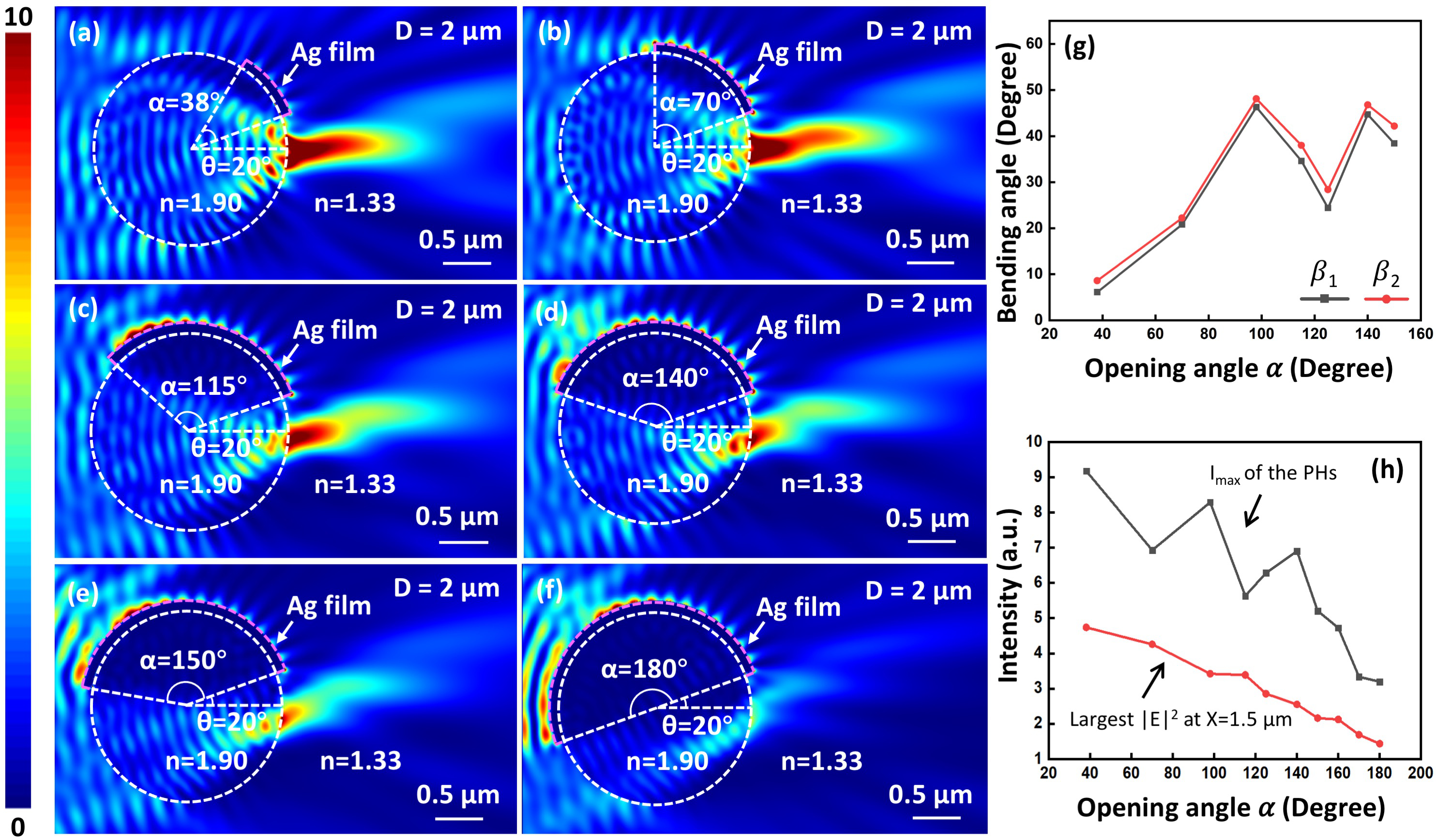
As shown in Figure 5, changing the opening angle of Ag films can effectively affect the characteristics of the obtained PHs. Figures 5(a)-(f) show the optical fields generated by 2 m-diameter patchy microcylinders in water. The opening angle of Ag films changes from =38∘ to =180∘ and the right edge of the Ag films are kept constant at =20∘. As shown in Figures 5(h),(g), the PH has the strongest intensity enhancement (=9.18) with a relatively small curvature (=6.1∘, =8.6∘) at =38∘ [Figure 5(a)]. The curvature of PHs becomes larger when the increases to 98∘, and its curvature drops quickly to =24.4∘ and =28.4∘ at =125∘. The bending angles finally reach to =38.4∘ and =42.2∘ at =150∘. S-PHs cannot be found in the patchy particle with an opening angle larger than 150∘, because most of the energy concentrated in the hot spot will disperse quickly into the free space. The maxium curvature obtained in this configuration is =46.3∘, =48.1∘ at =98∘ [Figure 5(g)].
As shown in the black line in Figure 5(h), the particle with a larger opening angle tend to have a smaller Imax. However, we can see some turbulence in the plot between =70∘ and =150∘. The Imax increases from 6.93 to 8.29 when the increases from 70∘ to 98∘, and drops to 5.63 at =115∘. This turbulence also can be found when increasing from 115∘ to 150∘. For all the opening angles, the Imax points are always at the right edge of the particle. The largest Imax obtained in this study is 9.18 at =38∘, and the minimum is 3.20 at =180∘. To avoid the turbulence caused by near-field effects, we also measured the maximum at X=1.5 m, and thus a smoother curve can be obtained, as shown in the red line in Figure 5(h). We can see that the light intensity decreases approximately linearly from 4.74 to 1.43 as the opening angle increases from 38∘ to 180∘.
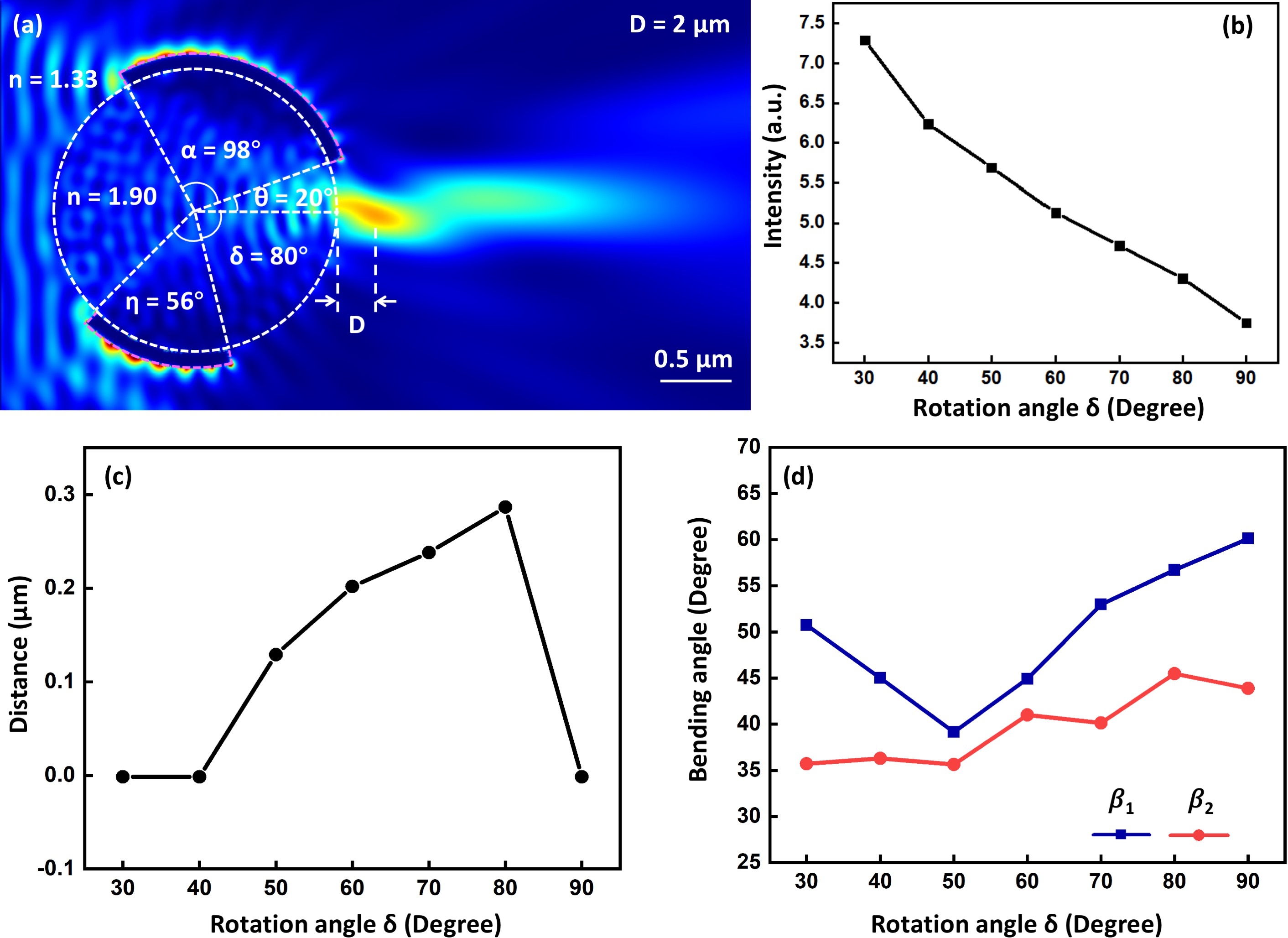
Next, we studied the generation of S-PHs from microcylinders with two separate patches of Ag films. As shown in Figure 6(a), the two patches have an opening angle of = 98∘ and = 56∘, respectively. The rotation angle of the patch on top is kept constant at = 20∘, and the rotation angle of the patch at bottom changes between = 30∘ to = 90∘. The Imax of the S-PHs decreases from 7.29 to 3.75 as the rotation angle increases from 30∘ to 90∘ [Figure 6(b)]. The pupil of the microcylinder is smaller at larger , leading to a smaller intensity enhancement factor. The Imax position of the S-PHs can be effectively adjusted by changing the angle. The largest gap between the Imax point and the microcylinder is 0.3 m [Figure 6(c)]. As shown in Figure 6(d), the bending angle tends to decrease between = 30∘ ( = 50.8∘) and = 50∘ ( = 39.2∘), and then goes higher until = 90∘ ( = 60.1∘). The bending angle increases slightly from = 35.7∘ to = 43.9∘ within this range. The maximum curvature can be obtained at = 90∘ with = 60.1∘ and = 43.9∘. Compared with the patchy particles covered by a single film, the particles with two patches can generate S-PHs with a much higher curvature and a tunable Imax position.
4 Conclusion
We proposed a method for the generation of S-PHs, a curved light field with S-shaped structures, which can be formed at the shadow side of a patchy particle due to the asymmetric flow of energy when light wave propagates through the patchy particle. The S-PHs studied in this work have a higher Imax and smaller FWHM than conventional PNJs. The characteristics of the S-PHs can be adjusted by changing the background refractive index, particle diameters and the coverage ratio of the patches. Moreover, the curvature of the S-PHs can be significantly enhanced using microcylinders covered with two patches, and the position of the Imax point can be adjusted by rotating the two patches. This new type of curved light may benefit various applications such as super-resolution imaging, micromachining, optical trapping, etc.
References
- [1] Zhigang Chen, Allen Taflove and Vadim Backman “Photonic nanojet enhancement of backscattering of light by nanoparticles: a potential novel visible-light ultramicroscopy technique” In Opt. Express 12, 2004, pp. 1214–1220
- [2] B. Yan et al. “Superlensing plano-convex-microsphere (PCM) lens for direct laser nano-marking and beyond” In Opt. Lett. 45, 2020, pp. 1168–1171
- [3] Z. Wang et al. “Optical virtual imaging at 50 nm lateral resolution with a white-light nanoscope” In Nat. Commun. 2, 2011, pp. 218
- [4] Ran Ye et al. “Experimental far-field imaging properties of a 5-m diameter spherical lens” In Opt. Lett. 38, 2013, pp. 1829–1831
- [5] F. Wang et al. “Scanning superlens microscopy for non-invasive large field-of-view visible light nanoscale imaging” In Nat. Commun. 7, 2016, pp. 13748
- [6] H. Yang, R. Trouillon, G. Huszka and M… Gijs “Super-resolution imaging of a dielectric microsphere is governed by the waist of its photonic nanojet” In Nano Letters 16, 2016, pp. 4862–4870
- [7] B.. Luk’Yanchuk et al. “Refractive index less than two: photonic nanojets yesterday, today and tomorrow” In Optical Materials Express 7, 2017, pp. 1821 DOI: https://doi.org/10.1364/OME.7.001820
- [8] Igor V. Minin, Cheng-Yang Liu, Yury E. Geints and Oleg V. Minin “Recent advances in integrated photonic jet-based photonics” In Photonics 7, 2020, pp. 41 DOI: https://doi.org/10.3390/photonics7020041
- [9] Igor Minin and Olge Minin “Diffractive optics and nanophotonics: resolution below the diffraction limit” In Springer 4 Springer, 2015, pp. 43–45
- [10] I.. Minin et al. “Experimental observation of a photonic hook” In Appl. Phys. Lett. 114, 2019, pp. 031105 DOI: https://doi.org/10.1063/1.5065899
- [11] Igor V. Minin et al. “Experimental demonstration of a tunable photonic hook by a partially illuminated dielectric microcylinder” In Opt. Lett. 45, 2020, pp. 4899–4902 DOI: https://doi.org/10.1364/OL.402248
- [12] Kishan Dholakis and Graham D. Bruce “Optical hooks” In Nature Photonics 13, 2019, pp. 229–230 DOI: https://doi.org/10.1038/s41566-019-0403-9
- [13] Q. Shang et al. “Super-resolution imaging with patchy microspheres” In Photonics 8, 2021, pp. 513 DOI: 10.3390/photonics8110513
- [14] Y. Fan et al. “Smart computational light microscopes (SCLMs) of smart computational imaging laboratory (SCILab)” In PhotoniX 2, 2021, pp. 19
- [15] O.. Minin and I.. Minin “Terahertz microscopy with oblique subwavelength illumination in near field” In Preprints, 2021 DOI: 10.20944/preprints202109.0024.v1
- [16] Liang Yue et al. “Photonic hook: a new curved light beam” In Opt. Lett. 43, 2018, pp. 771–774 DOI: https://doi.org/10.1364/OL.43.000771
- [17] Jianming Yang et al. “Ultra-narrow photonic nanojets through a glass cuboid embedded in a dielectric cylinder” In Opt. Express 26, 2018, pp. 3723–3731 DOI: https://doi.org/10.1364/OE.26.003723
- [18] G. Gu et al. “Photonic hooks from Janus microcylinders” In Opt. Express 27, 2019, pp. 37771–37780 DOI: https://doi.org/10.1364/OE.27.037771
- [19] Yury E. Geints, Alexander A. Zemlyanov, Igor V. Minin and Oleg V. Minin “Overcoming refractive index limit of mesoscale light focusing by means of specular-reflection photonic nanojet” In Opt. Lett. 45, 2020, pp. 3885–3888 DOI: https://doi.org/10.1364/OL.398367
- [20] Cheng-Yang Liu, Hung-Ju Chung, Oleg V Minin and Igor V Minin “Shaping photonic hook via well-controlled illumination of finite-size graded-index micro-ellipsoid” In Journal of Optics 22, 2020, pp. 085002 DOI: https://doi.org/10.1088/2040-8986/ab9aaf
- [21] F. Tang et al. “Generation of photonic hooks from patchy microcylinders” In Photonics 8, 2021, pp. 466 DOI: 10.3390/photonics8110466
- [22] Guoqiang Gu et al. “Inflection point: a perspective on photonic nanojets” In Photonics Res. 9, 2021, pp. 1157–1171 DOI: https://doi.org/10.1364/PRJ.419106
- [23] Cheng-Yang Liu, Hung-Ju Chung and Hsuan-Pei E “Reflective photonic hook achieved by a dielectric-coated concave hemicylindrical mirror” In J. Opt. Soc. Am. B 37, 2020, pp. 2528–2533 DOI: https://doi.org/10.1364/JOSAB.399434