OpenVVC: a Lightweight Software Decoder for the Versatile Video Coding Standard
Abstract
In the recent years, users requirements for higher resolution, coupled with the apparition of new multimedia applications, have created the need for a new video coding standard. The new generation video coding standard, called Versatile Video Coding (VVC), has been developed by the Joint Video Experts Team, and offers coding capability beyond the previous generation High Efficiency Video Coding (HEVC) standard. Due to the incorporation of more advanced and complex tools, the decoding complexity of VVC standard compared to HEVC has approximately doubled. This complexity increase raises new research challenges to achieve live software decoding. In this context, we developed OpenVVC, an open-source software decoder that supports a broad range of VVC functionalities. This paper presents the OpenVVC software architecture, its parallelism strategy as well as a detailed set of experimental results. By combining extensive data level parallelism with frame level parallelism, OpenVVC achieves real-time decoding of UHD video content. Moreover, the memory required by OpenVVC is remarkably low, which presents a great advantage for its integration on embedded platforms with low memory resources. The code of the OpenVVC decoder is publicly available at https://github.com/OpenVVC/OpenVVC.
Index Terms:
Video compression, VVC, decoding, software, real-time, low memory.I Introduction
During the last decade, the extensive use of on-line platforms and the democratization of higher resolutions (4K, 8K) have lead to a significant increase in the volume of exchanged video content [1]. The multimedia services have also diversified with the apparition of video applications that offer immersive and more realistic viewing experience, such as Virtual Reality (VR, 360∘). This increasing demand for video content brings new challenges to compression, mostly to enhance the video coding efficiency and reduce the carbon footprint induced by video storage, transmission and processing. Finalized in July 2020, VVC [2, 3] is the State-of-the-Art (SOTA) video coding standard. VVC has reached the ultimate goal of up to 50% bit-rate saving compared to HEVC for similar subjective video quality [4, 5].
The bit-rate savings brought by VVC standard over HEVC are achieved at the expense of more complex coding tools at both encoder and decoder sides. The computational complexity of the VVC reference encoder has increased by a factor 8 and 27 compared to the HEVC reference encoder in inter and intra coding configurations, respectively [6]. At the decoder side, which is the focus of this paper, the computational complexity increase of VVC standard compared to HEVC has doubled (2x) in both inter and intra coding configurations [7]. This decoding complexity increase raises new research challenges for VVC deployment, especially on embedded platforms or for live applications that require real-time decoding capability.
Usually, hardware decoders [8] are preferred to software decoders for embedded platforms with low memory and energy supplies. However, hardware decoders will only be commercialized several years after the standard finalization. The design of efficient software solutions is therefore mandatory during the next couple of years to support real time decoding of the emerging video applications. For these applications, the flexibility of software decoders is crucial to support the minor evolution of a standard (ie. new extended profiles), as well as for their deployment on previous generation devices, which do not embed a VVC hardware decoder. Currently only few software decoders compliant with the VVC standard have been implemented. The VVC reference software VVC Test Model (VTM) [9], for instance, is compatible with the complete set of new coding tools but requires high memory usage and achieves poor decoding frame rate performance [7]. From the source code of the VTM, the Fraunhofer Heinrich Hertz Institute has developed a VVC decoder named VVdeC [10]. This latter offers high decoding speed, at the cost of high memory consumption.
In this paper, we present an open source VVC software decoder named OpenVVC. The software architecture, parallelism strategy as well as detailed experimental results are described in this paper. OpenVVC is developed in C programming language and compiled as a cross-platform library. It provides real time decoding capability under various operating systems including MAC OS, Windows, Linux and Android, targeting sustainable real-time decoding of Ultra High Definition (UHD) content on high performance General Purpose Processor (GPP) and low performance GPP platforms. OpenVVC is compatible with popular video players such as FFplay [11], VLC and GPAC. Current version of OpenVVC decoder supports the decoding of a wide set of conformance videos in addition to the four principal coding configurations defined by Joint Video Experts Team (JVET): All Intra (AI), Random Access (RA), Low-Delay P (LDP) and Low-Delay B (LDB).

The OpenVVC decoder has been designed to achieve high decoding speed, with the lowest possible memory usage. The decoder relies on Single Instruction on Multiple Data (SIMD) optimizations [12] to reduce the decoding time of the most computationally complex operations. The architectures of multi-core processor are exploited through frame level parallelism, where several frames are processed simultaneously by the decoder. By combining these two levels of parallelism on a multi-core x86 platform111High performance GPP: https://www.intel.fr/content/www/fr/fr/products/sku/134594/intel-core-i712700k-processor-25m-cache-up-to-5-00-ghz/specifications.html, OpenVVC decoding speed reaches over 290 Frames Per Second (fps) and 90 fps for Full High Definition (FHD) and UHD resolutions, respectively. Moreover, this high decoding speed is achieved at a very low memory usage. The sequential decoding of FHD content requires less than 25 MB and 75 MB in AI and RA configurations, respectively.
The rest of this paper is organized as follows. Section II presents the general block diagram of a VVC decoder and the main decoding stages. The Section also provides an overview of the SOTA parallelism techniques for the decoding process and presents the VVC software decoders currently available. The proposed OpenVVC decoder architecture and optimizations are described in detail in Section III. Section IV presents the experimental setup, as well as the performance in terms of memory consumption and decoding speed of OpenVVC decoder in AI and RA coding configurations. In order to highlight the most time consuming tasks of the decoding process, the complexity of OpenVVC is also provided by group of tools. Finally, Section V concludes the paper.
II Background and related work
In this section we first give the main normative tools integrated in the VVC standard and then describe optimizations and parallel processing techniques used to speedup the decoder along with existing software VVC decoders.
II-A Overview of VVC decoder
Fig. 1 presents the general block diagram of a VVC decoder, where each block corresponds to one of the main decoding stages. The decoder converts an input bitstream composed of binary symbols (bits) into decoded pictures, based on the conventional hybrid coding that takes advantage of both intra/inter prediction and transform coding. The operating principles of the decoding stages in Fig. 1 are introduced in this section, without going into in-depth details. For a detailed description of the VVC tools, the reader may refer to the following papers [6, 2].
II-A1 Entropy decoding
The first decoding stage is the entropy decoding of the bitstream. The Context Adaptive Binary Arithmetic Coding (CABAC) [13], first introduced in Advanced Video Coding (AVC) standard, is the entropy engine used in VVC. At encoder side, the CABAC has compacted in the bitstream all the syntax elements generated by the coding tools. These syntax elements include among others block partitioning information, intra and inter predictions information, quantized coefficients or in-loop filtering parameters. At decoder side, the entropy decoding stage parses the binary symbols in the bitstream, and converts them into non-binary symbols. These non-binary symbols are provided as input data for all the other decoding stages.
II-A2 Predicted block
At the encoder side, the block partitioning scheme divides the picture into appropriate block sizes according to the local activity of the samples. The block partitioning scheme divides recursively a large block of typical dimension 128128, called Coding Tree Unit (CTU), into smaller blocks of sizes in the range 128 64, 64 128 to 4 4 samples, called Coding Units (CUs). At the decoder side, the CU dimensions are retrieved by the entropy decoder and each CU is reconstructed by summing a residual block with a predicted block.
The predicted block is an approximation of the original block, computed using intra prediction, inter prediction or a combination of both intra and inter predictions. Intra prediction exploits spatial redundancy within the same frame, whereas inter prediction exploits temporal redundancy among adjacent frames. In VVC, the novel Combined Intra/Inter Prediction (CIIP) tool combines inter and intra predicted blocks as a weighted sum in order to generate the final predicted block.
When the CU is intra predicted, a prediction mode, as well as the previously reconstructed samples of adjacent left and above CUs are required. These neighboring samples are either propagated with a given angle (angular and Wide Angular Intra Prediction (WAIP) modes), averaged (DC mode), interpolated (Planar mode) or used as input for alternative Matrix-based Intra Prediction (MIP) mode [14]. The Multiple Reference Line (MRL) mode [15] introduced in VVC enables the encoder to choose among three reference lines and explicitly signal the one performing the lowest rate-distortion cost.
For inter prediction, the samples of current CU are approximated based on the reference samples stored in the Decoded Picture Buffer (DPB). This process is called Motion Compensation (MC). The decoder first derives one or several Motion Vectors (MVs) (whether the CU is uni or bi-predicted) from CABAC information. Each MV is composed of a vertical and an horizontal components, representing the underlying samples translation from the reference picture to current picture. For bi-predicted blocks, a blending process is applied to aggregate the two motion compensated blocks.
In VVC, the Luma Mapping with Chroma Scaling (LMCS) has been introduced [16] operating in three distinct parts of the decoding process: residual chroma-scaling, forward luma mapping for inter prediction and inverse luma mapping of the reconstructed block. For inter prediction, the LMCS modifies the luma predicted samples with a forward luma mapping. This process maps (i.e. redistributes) the inter predicted luma samples to another range of values. The residual block being also distributed in the entire possible range of values, this operation is mandatory to sum the inter predicted block with the residual block.
II-A3 Residual block
The inverse quantization and inverse transform are crucial decoding stages in conventional hybrid video codecs. The inverse quantization retrieves the value of the transformed residual coefficients, taking as input the quantized coefficients transmitted in the bitstream. The transformed residual coefficients are further converted into a non-scaled residual block by the inverse transform. The chroma-scaling part of the LMCS is finally applied on the non-scaled residual block. The scaling factor applied to the chroma samples is computed based on the luma samples of the reconstructed block. The inverse transform module consists in the inverse Low Frequency Non-Separable Transform (LFNST) and the inverse Multiple Transform Selection (MTS).
II-A4 In-loop filters
Four in-loop filters are performed on the reconstructed samples in order to reduce the visual artifacts of previous coding tools. They include the inverse mapping of the LMCS, the Deblocking Filter (DBF), the Sample Adaptive Offset (SAO) and the Adaptive Loop Filter (ALF). First, the inverse mapping of the LMCS redistributes the reconstructed luma samples from the entire possible value range to a smaller range of values. Samples in this smaller range of values will be used by all the following in-loop filters and will be stored in the DPB.
The DBF [17] is applied on block boundaries, reducing the blocking artifacts introduced among others by quantization. In the decoding process, the horizontal filtering for vertical edges is first performed, followed by vertical filtering for horizontal edges. The SAO [18] then classifies the reconstructed samples into different categories to alleviate the remaining artefacts sample by sample. For each category, an offset value, retrieved by the entropy decoder, is added during the SAO process to each sample of the category. The SAO is particularly efficient to filter the ringing artefacts and enhance the perceptual video quality.
The last in-loop filters are the ALF [19] and Cross Component ALF (CC-ALF) [20]. The ALF performs Wiener filtering to minimize the Mean Squared Error (MSE) between original and reconstructed samples. It is responsible for an important share of VVC decoding complexity [21], mostly due to the classification of every 44 block of samples and to the application of diamond shape filters on both luma and chroma samples. Applied in parallel with ALF, the CC-ALF relies on the luma samples to adjust the chroma samples value.
Once the in-loop filters are performed on the entire picture, the decoded picture is stored in the DPB.
II-B Sate-of-the-art of VVC decoding
The total video decoding workload is determined at the encoder side since it mainly depends on the set of enabled coding tools and on the bitstream final size [22]. The challenges for a VVC decoder are speed and compliance with the standard to support real time decoding of a wide range of bitstreams encoded by different encoders, rates and resolutions. The speed challenge is addressed by parallel processing techniques, which aims to distribute optimally the decoding workload on several actors.
In this Section, we first describe the SOTA for parallel decoding techniques. Since only few works on VVC decoders are currently available, many of the presented related works are designed for HEVC decoding process. It is nonetheless possible to adapt these techniques to a VVC decoder, considering that the decoding process of HEVC and VVC standards are quite similar. The second part of this section presents the VVC software decoders currently available.
The parallel processing of a decoder essentially operates at three levels of parallelism: data level, high level and frame level. The data level parallelism techniques are applied on elementary operations. They include among other techniques relying on SIMD instructions [12]. In high level parallelism techniques, several threads operate on continuous regions of the same frame. These techniques are either normative, i.e. defined in the standard and require additional information in the bitstream, or non-normative. With frame level parallelism techniques, several frames are processed in parallel, under the restriction that the MC dependencies are satisfied [23].
II-B1 Data level parallelism
In the video decoding field, data level parallelism is widely explored through techniques relying on SIMD optimizations [24, 25, 23]. With a single SIMD instruction, an operation is applied simultaneously on a vector of data, producing a vector of results. For x86 processors, various SIMD set of instructions are available (mainly Streaming SIMD Extensions (SSE) [26] and Advanced Vector eXtensions (AVX) [27]). For instance, the SSE2 [28] supports instructions on 128-bit registers, which is 2 and 4 times shorter compared to AVX 2 and AVX 512 operating on 256-bit and 512-bit registers, respectively.
The computations that benefit from SIMD architectures are typically those including elementary operations on vectors and matrices. In the decoding process, these computations include among others the application of the diamond shape filters of the ALF, the process of the MC interpolation filter, the derivation of reconstructed samples in intra prediction and the inverse transform applied on the residual transform coefficients. On the other hand, the entropy coding stage does not include significant data level parallelism which makes the use of SIMD instructions unnecessary.
Related works widely rely on SIMD architectures to speed up the decoding process. Yan et al. [25] rely on intensive SIMD optimizations (SSE instructions on 128-bit registers) to reduce the HEVC decoding time. The Neon instructions set [29], available on low performance GPP processors, is exploited by Raffin et al. in their work [30]. In the particular case of the scalable extension of HEVC standard, named Scalable High Efficiency Video Coding (SHVC), Hamidouche et al. [23] optimize among other the upsampling of the base layer picture with SIMD instructions. A complete summary of the possible SIMD optimizations for HEVC decoding process is provided by Chi et al. [24]. The authors discuss the challenges of the SIMD implementation for many of the most complex decoding computations, and provide experimental results on 14 different platforms.
II-B2 Normative high level parallelism
The normative high level parallelism techniques are defined in the standard and require conveying additional information in the bitstream. This subsection presents two of the most widely used normative techniques, namely tiles [3] and Wavefront Parallel Processing (WPP) [31]. They have been standardized in both HEVC and VVC in order to facilitate the use of parallel processing architectures for encoding and decoding. The proposed OpenVVC decoder for instance is compliant with bitstreams including both tiles and WPP.
Tiles
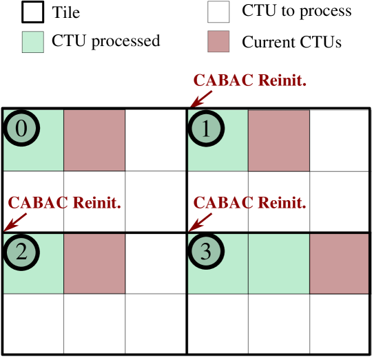
In both VVC and HEVC standards, tiles are rectangular regions of the picture containing entire CTUs [3]. In Fig. 2, the tile partitioning forms a 22 grid. They are labeled from 0 to 3 and delimited by the thicker black lines. Prediction dependencies across tile boundaries are broken and entropy encoding state is reinitialized for each tile. These restrictions ensure that tiles are independently decoded, allowing several threads to decode simultaneously the same picture. The in-loop filtering stages across tile boundaries must however be performed when the reconstructed samples of all tiles are available.
In [22], the tile partitioning is adapted at the encoder side in order to minimize the decoding time. The decoding load imbalance among tiles is reduced based on the relation between the decoding time and the number of coded bits of a given CTU. In the context of computing systems with asymmetric processors, Yoo et al. [32] take advantage of tile partitioning flexibility in order to optimize HEVC decoding time on these specific platforms. Asymmetric tile work load is delivered at encoder side by varying tile sizes. At the decoder side, the large and small tiles are further allocated to fast and slow cores, respectively.
Wavefront Parallel Processing
The WPP tool, enabled at the encoder side, divides the picture into CTU rows [31]. The CABAC context is reinitialized at the start of each CTU row with the CABAC context of at least the second CTU in the preceding row. In VVC, WPP removes the dependency to the top-right CTU, thus reducing the CTU-offset required between adjacent lines. The decoding of a row may therefore begin once the first CTU in the preceding row is reconstructed, since it ensures that the decisions needed for prediction and CABAC reinitialization are available. These constraints allow several processing threads to decode the picture in parallel, with a delay of one CTU between adjacent rows. The propagation of these delays across the picture rows limits the parallelism speedup, especially for high number of threads. For this reason, many works including [33] and [34] combine WPP tool with frame level parallelism in their solutions. Zhang et al. [34] show that the decoder combining frame level parallelism and WPP enables much higher speedup compared to the decoder using WPP alone, as soon as the number of threads exceeds 5 for high resolution video.
II-B3 Non-normative high level parallelism
In opposition with decoding parallelism techniques that require specific processing at encoder side, the parallelism techniques presented in this section have not been standardized and are suitable to decode any input bitstream. For instance, task level parallelism techniques refer to techniques in which several threads process simultaneously one or several decoding tasks, exploiting their specific parallel opportunities. A detailed description of the main task level parallelism opportunities is provided in [35]. Entropy decoding process is sequential and thus it is the most difficult stage to process in parallel. In order to process the CABAC in parallel, CABAC reinitialization must be included in the bitstream at encoder side, as presented in tiles or WPP high level parallelism techniques. Habermann et al. [36] propose three solutions to improve the CABAC processing in WPP for low-delay applications.
Once the CABAC output data is retrieved, the other decoding tasks may be performed in parallel. Two main approaches exist to retrieve the CABAC output data in related works. The first approach performs the CABAC stage on a picture basis, as a pre-processing of the picture reconstruction. This approach, adopted in the VTM and in recent works [35, 37], is optimal for task level parallelism. However, it requires additional memory to store of the CABAC output data of the whole picture. Another approach consists in retrieving the CABAC information on the fly [23]. With this approach, task level parallelism is disabled but the memory consumption to store CABAC output is negligible. In this work, the second approach is adopted to lower the memory footprint. The task level parallelism opportunities are therefore not exploited.
For in-loop filtering, a classical approach consists in processing the in-loop filter in a separate pass once the entire picture is reconstructed. A slight synchronization overhead is introduced in this case since the in-loop filters are applied one by one on the entire picture. Kotra et al. [38] provide three parallel implementations of the DBF on the entire reconstructed picture for HEVC decoding. The limit of this approach is that the final samples needed as reference for MC are available only after the last in-loop filter is processed on the entire picture. However, when in-loop filters are performed on a CTU level, the final samples are available at lower delay. For instance in [39], the final samples of a CTU are available with a delay of 2 CTUs. In the proposed solution, the in-loop filtering is applied at a CTU line level. This approach improves the frame level parallelism in inter configuration compared to processing the in-loop filter on the entire picture.
II-B4 Frame level parallelism
With frame level parallelism, the decoder processes several frames in parallel, under the restriction that the MC dependencies are satisfied. Frame level parallelism is particularly efficient in AI coding configuration since there are no MC dependencies. In inter coding configuration, its efficiency highly depends on the motion activity in the sequence and on the ranges of MVs used for MC. Based on this observation, Chi et al. [33] restrict at the encoder side the downwards motion to 1/4 of image height. This restriction reduces greatly the MC dependencies for the decoding process, without impacting significantly the coding efficiency.
Frame level parallelism requires a large memory overhead compared to sequential decoding, since the decoder must store additional picture buffer per decoding thread. For systems with strong memory constraints such as mobile devices, this memory overhead is a serious limitation. For instance in the context of mobile devices, authors in [40] rely on high level parallelism techniques rather than frame level parallelism alone to accelerate the HEVC decoding process.
II-B5 VVC software decoders
Currently only few open-source software VVC decoders have been implemented. The first to be highlighted is the VTM [9], the reference software in which the new tools have been validated during the standardization process. Its main advantage is its compatibility with the complete set of new VVC standard tools. It has been extensively used during OpenVVC development to validate the proper implementation of the new coding tools. However, it requires high memory usage and achieves decoding performance far from real time [7].
The Fraunhofer Heinrich Hertz Institute has developed an open-source VVC decoder named VVdeC [10], from the source code of the VTM as a starting point. Based on VVdeC software, the work of Wieckowski et al. [37] provides one of the first experimental results on a real-time VVC decoder. The authors propose intensive SIMD optimizations through SSE 42 (128-bits register) and AVX 2 (256-bits register) instruction sets. These optimizations are coupled with task level parallelism, which does not require normative parallel techniques.
A recent alternative decoder has been proposed by the Tencent Media Lab O266dec [41]. This decoder is only available as a binary for testing purpose. Zhu et al. [42] describe the operating principle and experimental results of O266dec decoder in RA configuration. The authors combine SIMD optimization (256-bit register instruction set AVX 2) with techniques exploiting various levels of parallelism: task level, CTU level, sub-CTU level and frame level. The decoding speed for FHD and UHD video content is very promising. However, the task level and CTU level parallelism require the storage of the CABAC information on a picture basis, which may increase the memory consumption.
.
Since 70% of the world population will have mobile connectivity by 2023 according to Cisco [43], the optimization of the decoding process on low performance GPP platforms222Low performance GPP: https://developer.arm.com/tools-and-software/open-source-software/arm-platforms-software is a crucial issue. To tackle this concern, Saha et al. [21] optimize the VVdeC decoder for a system on chip heterogeneous platform composed of a low performance GPP and Graphical Processing Unit (GPU) processor. The SSE and AVX instructions included in VVdeC are converted to the Neon instruction set available on low performance GPPs. The results presented do not yet exploit the GPU processor, which may decrease the processing time of computationally complex decoding tasks. A similar effort was accomplished by Li et al. [44] to optimize O266dec decoder for various low performance GPP platforms. The reader can refer to [45] for the exhaustive list of available VVC encoders and decoders.
III OpenVVC decoder
The presented VVC decoder is based on the open source OpenVVC project. The contributors to OpenVVC also developed the open source software decoder OpenHEVC [46] compliant with HEVC standard, used in widespread players such as VLC333VLC player: https://www.videolan.org/index.fr.html and GPAC [47]. As previously mentioned, the decoder is implemented in C programming language, and is integrated as a dynamic library with FFmpeg player444OpenVVC library embedded in FFmpeg https://github.com/OpenVVC/OpenVVC. The project aims to implement a conforming VVC decoder and supports the Common Test Conditions (CTC) [48] in AI, RA and Low-Delay (LD) configuration for 10/8-bits input content.
This section describes the OpenVVC general architecture, its buffer characteristics and the implemented parallelism strategies.
III-A Decoder architecture
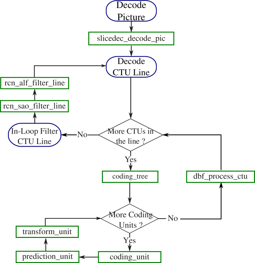
The decoding parameters required at the sequence, picture, slice or tile level are first retrieved by parsing global parameter sets such as the Sequence Parameter Set (SPS), Picture Parameter Set (PPS), picture header or slice header. The general block diagram for the decoding of a frame in OpenVVC is presented in Fig. 3. The main tasks of the decoding process, previously detailed in Section II, are applied at various levels:
-
•
The CU level reconstruction includes the intra/inter prediction, inverse quantization, inverse transform and LMCS (included in prediction_unit method).
-
•
The DBF is applied at CTU level, right after all the CUs of the CTU are reconstructed. This choice avoids the storage of the Quantization Parameter (QP) map and CU dimensions, required by the DBF, on a larger scale.
-
•
The SAO filter is applied at a CTU line level followed by the ALF/CC-ALF. This approach improves the frame level parallelism in inter configuration compared to processing the in-loop filters after reconstruction of the entire frame.
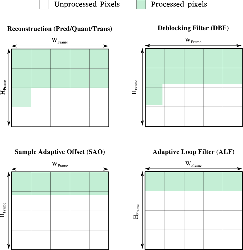
The decoding process of OpenVVC is performed in four successive steps (reconstruction, DBF, SAO, ALF) as illustrated in Fig. 4. The upper-left sub-figure shows the progress of the reconstruction stages : prediction, inverse quantization and transform. In green, the two first CTU lines are completely reconstructed. As mentioned previously, the DBF (upper-right sub-figure) is applied right after the reconstruction on almost all the samples of the current CTU. A margin of 8 samples is left un-processed at the bottom and at the right of current CTU, and will be processed once the required reconstructed samples are available. For SAO filter, a delay of 1 CTU line is introduced. The first CTU line is entirely processed, as well as a margin of 3 pixel rows in the second CTU line. This margin is mandatory to apply the ALF (bottom-right sub-figure) on the entire first CTU row. The final samples needed as reference for MC of other frames are therefore available with a delay of only 1 CTU line.
III-B Frame level buffers management
The decoding of a picture in chroma format requires a picture buffer with dimensions , with and the picture width and height, respectively. The same picture buffer is used to store all intermediate pixel values during the decoding process. The values of the reconstructed samples are overwritten by the DBF pixel values, that are further overwritten by the SAO values and finally replaced by the ALF output values. To ensure that the decoder does not lose intermediate data required for specific stages, local lightweight buffers are used as a complement and are described in next Section III-C.
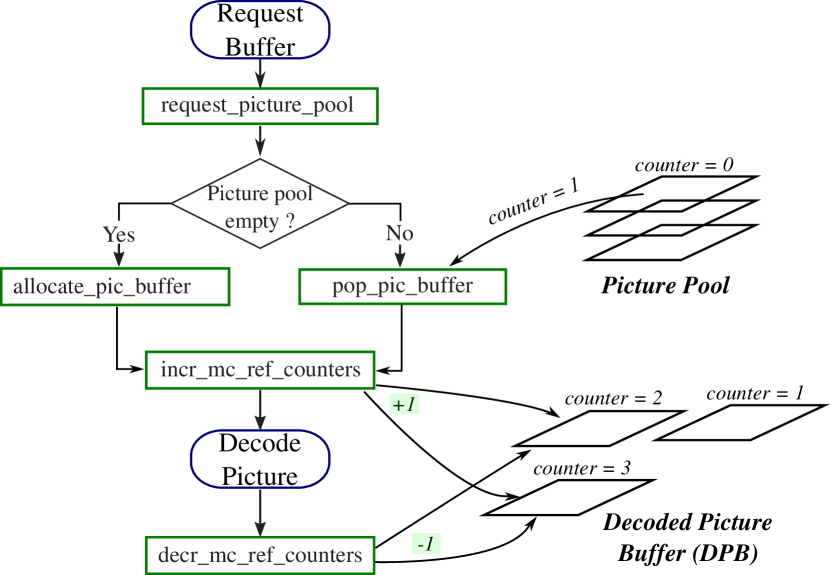
The picture buffers are counted and a picture pool system manages the unused resources in order to avoid buffer re-allocation (which is time and memory consuming). On the other hand, a DPB structure stores the decoded frames that are required for display or used as reference for MC. Fig. 5 illustrates the DPB management and picture pool in OpenVVC. When the decoding of a picture starts, the decoder requests a picture buffer to the picture pool. A new picture buffer is allocated only when the picture pool is empty. Otherwise, the decoder uses a picture buffer popped from the picture pool. Then, the decoder increments the counters of the frames in the DPB required as reference for MC by the current frame. The counters of the reference frames are further decremented when the current picture is decoded. When a picture counter falls to 0, it is equivalent to say that it is currently not required neither for display nor as reference for MC.
An important aspect for memory consumption limitation, is to remove the unused picture buffers as soon as possible from the DPB. In the bitstream, an integer dpb_max_nb_pic is transmitted, signaling the maximum number of frames needed in the DPB for the decoding of a sequence. When the current number of frames in the DPB exceeds dpb_max_nb_pic, the picture with counter equal to 0 and with minimal Picture Order Count (POC) is removed from the DPB and then is stored in the picture pool.
The MV buffers required for the application of the novel Temporal Motion Vector Prediction (TMVP) tool are also stored on a frame level. These MV buffers contain a MV for every pixel block of the reference frames. A MV buffer pool with similar operating principle as the picture buffer pool is implemented in order to avoid buffer re-allocation.
III-C Local-level buffers management
The local structure and buffer dimensions have been designed to operate on a CTU level. As mentioned in Section II-B3, the CABAC output data required to decode the CTU is retrieved on the fly and not stored in the local structure. This approach reduces substantially the memory consumption compared to the storage in a frame-basis of the CABAC output. The local structure includes the CTU transform residual and MV information. Moreover, several decoding stages require intermediate samples belonging to neighboring CTUs, including intra prediction, SAO and ALF. The intermediate pixel values are stored in local buffers, and a considerable effort has been made to minimize their dimensions. The dimensions of the local buffers are shown in Fig. 6, and their usage is further described in this section.

A single buffer of CTU dimensions, called extended CTU (EC) buffer, is used to decode the CTU. The EC buffer is a square block of dimensions , with the margin of neighboring CTU samples. In addition to the EC buffer, each of the 3 decoding stages previously mentioned relies on Right Columns (RC) and Bottom Rows (BR) buffers. The dimensions of the local buffers are shown in Fig. 6. The BR buffer is a rectangle of dimension containing the bottom samples of upper CTU line. The RC buffer is a rectangle of dimension , containing the right samples of the left CTU. The selected margin depends on the decoding stage. For intra prediction, since the MRL intra prediction mode requires 3 reconstructed pixel columns on the left. For in-loop filters, the margin is half the filter dimension. Therefore, for the SAO and for the ALF.
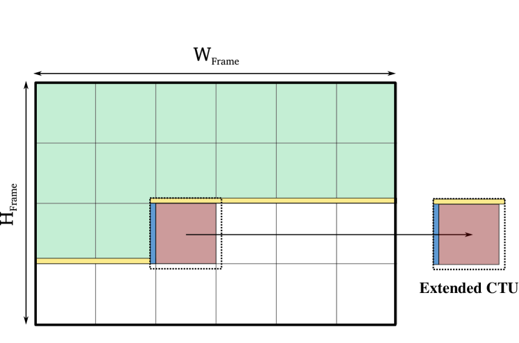
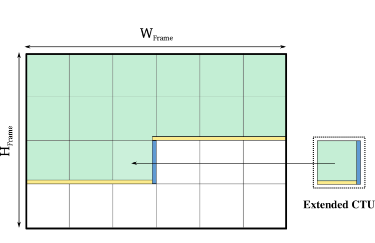
Fig. 7 illustrates the use of the local buffers for the processing of a given CTU. The processes considered in this paragraph are either intra prediction, SAO or ALF. As shown in Fig. 7(a), the EC buffer is first filled with unprocessed samples, i.e. samples on which the process has not been applied. The CTU area, of dimension , as well as the bottom and right margins are filled directly with the content of the picture buffer. The left margin is filled with the unprocessed samples of the left CTU, previously stored in the RC buffer. The upper margin is filled with the unprocessed samples of the upper CTU, previously stored in the BR buffer. The second step is shown in Fig. 7(b). The RC and BR buffers are updated with samples of current CTU before processing. They will be used during the process of the following CTUs. Finally, the process is applied on the CTU area of the EC buffer that is further copied in the decoded picture.
Resolution Global Context Local Context Picture Buffer MV Buffers FHD 5 kB 741 kB 8.3 MB 130 kB UHD 6 kB 750 kB 33.2 MB 620 kB
TABLE I summarizes the memory consumption of the OpenVVC buffers and structures, with chroma format 4:2:0, input bit depth 10 and CTUs. The global context structure contains decoding parameters required at the sequence, picture, slice or tile level. Since part of the global context parameters are stored on a CTU basis, the buffer memory consumption varies slightly from FHD to UHD sequences. The local context structure contains local information required to decode a CTU, as well as the local buffers described in Section III-C. The local buffers include the BR buffer of dimension , that is larger for UHD resolution compared to FHD. For this reason the memory consumption is 741KB for FHD and 750KB for UHD. The picture buffer has the dimensions of the picture and is therefore 4 times larger for UHD compared to FHD resolution. The same observation applies to MV buffer used for TMVP, described in Section III-B. TABLE I shows that the largest share of the memory is consumed by the picture and the local buffers.
III-D Parallelism strategies
OpenVVC decoder currently supports data level parallelism, frame level parallelism, as well as normative slice level and tile level parallelism (both dynamic and static) defined in the VVC standard. In this work, we only present the results generated with the combination of data level parallelism and frame level parallelism.
III-D1 SIMD optimization
Module Method Transform Inter-Component Transform (ICT) DST VII, DCT II, DCT VIII Low-Frequency Non-Separable Transform (LFNST) Motion Compensation Luma 8-tap filters Chroma 4-tap filters Decoder-side Motion Vector Refinement (DMVR) Bi-Directional Optical Flow (BDOF) Prediction Refinement with Optical Flow (PROF) Intra Prediction DC/Planar Cross Component Linear Model (CCLM) Matrix-based Intra Prediction (MIP) In-Loop Filters ALF block classification ALF diamond shape filters SAO filter (Edge and Band)
For data level parallelism, OpenVVC relies on SIMD instruction set SSE 42 [26] operating on 128 bits registers. Several computationally expensive methods are optimized with SIMD instructions, which are summarized in TABLE II. They are mainly distributed into 4 modules : transform, motion compensation, intra prediction and in-loop filters. Many tools in TABLE II have been introduced in VVC standard, including Inter-Component Transform (ICT), Low-Frequency Non-Separable Transform (LFNST), Cross Component Linear Model (CCLM), MIP and ALF. These tools carry-out computations that benefit from SIMD architectures, since they apply elementary operations at sample level. In particular, the SIMD optimization divides by 4 the time consumption of the ALF diamond shape filters. In the future, OpenVVC will also rely on SIMD instruction sets with larger registers such as AVX 2 (256-bits) or AVX 512 (512-bits), which will further improve the speed-up offered by data-level parallelism.
III-D2 Frame level parallelism
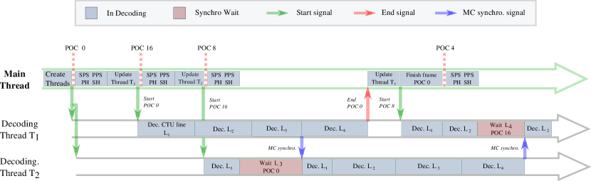
With frame level parallelism, the decoder processes several frames in parallel, under the restriction that the MC dependencies are satisfied. Regarding the memory usage, each thread requires separate picture buffer (see Section III-B) and local buffers (see Section III-C). Fig. 8 shows an example of a decoding time-line in RA configuration with a main thread and 2 decoding threads. The main thread is responsible for the parsing of global parameter sets such as the SPS, PPS, picture header or slice header. It also manages the scheduling of the decoding threads through a thread pool. Since only frame level parallelism is enabled in this work, the scheduling management of the decoding threads is straightforward. Once the global parameter sets of a picture are parsed, the main thread selects the first available decoding thread in the pool and updates its internal structures with the data required to decode the frame. The main thread further signals to the decoding thread (green arrows in Fig. 8), which starts the decoding of the frame. When the decoding thread finishes the picture processing, it signals to the main thread (red arrow in Fig. 8) and becomes available again in the thread pool.
The MC synchronization between decoding threads is also a crucial issue for frame level parallelism in inter coding configuration. When a decoding thread requires samples not yet available for MC, it waits until these samples are reported as available by the thread decoding the reference frame. In the example of Fig. 8, the thread decodes CTU line in picture and requires the reference data of CTU line in picture . The thread waits until thread reports available samples in CTU line of picture (blue arrows in Fig. 8), and further continues the decoding of picture . As explained in Section III-A, the decoding and in-loop filtering processes are performed on a CTU line basis in OpenVVC. For this reason, the samples are reported available as reference for MC on a CTU line basis, once the last in-loop filter is applied.
IV Experimental results
This section presents the experimental setup, as well as the performance in terms of memory usage and frame-rate of the proposed OpenVVC decoder in both AI and RA coding configurations. Data level and frame level parallelism performance is discussed and compared to two open-source SOTA VVC decoders: VTM-16.2 and VVdeC-1.5. In order to highlight the most time consuming tasks of the decoding process, the complexity repartition of OpenVVC is also provided under the form of pie charts.
IV-A Experimental setup
The following experiments are conducted with the proposed OpenVVC decoder, in comparison with the VTM-16.2 and VVdeC VVC decoders. These three open-source software decoders are built with gcc compiler version 11.3.1, under Linux OS version 5.17.6-200 as distributed in Fedora 35. The bitstreams decoded during the experiments are generated with the VTM-11.2 encoder. The platform setup is composed of a 12 cores GPP: 8 Performance cores (P-cores) and 4 Efficient cores (E-cores) Central Processing Units (CPUs) running at 3.70 GHz for P-core and 3.60 GHz for (E-core), as detailed in TABLE III. Each core has 80KB L1 cache (per core), 1.25MB L2 cache (per core) and 25MB L3 cache (shared). Moreover, the decoding process is forced to be executed on the P-cores and a single set of SIMD instructions is enabled during these experiments (SSE4.2 - 128 bits registers), in order to provide a fair comparison between the software decoders.
CPU High performance GPP Cores 8 P-cores + 4 E-cores Clock Rate 4.70 GHz (P-core) / 3.60 GHz (E-core) SIMD Instructions SSE42 - 128 bits registers Memory 32 GB Cache (L1, L2, L3) 80 KB / 1.25 MB / 25 MB Compiler Linux 5.17.6-200-fc35 Decoder Version OpenVVC v1.1.0 Alternative Decoders VTM-16.2 / VVdeC-1.5 Encoder Version VTM-11.2
The complexity increase of VVC decoding process raises a critical issue mainly for high resolution video sequences. For this reason, the test sequences selected in this work include 5 High Definition (HD) (classes E and F, 1280720 samples), 6 FHD (classes B and F, 19201080 samples) and 6 UHD (class A, 38402160 samples) video sequences included in the CTC [48]. Current version of OpenVVC is compatible with the encoding tools enabled in the CTC, in both AI and RA configurations. The performance of the OpenVVC decoder is assessed at various bit-rates, obtained with QP values of following the CTC.
The memory consumption of the software and the output frame-rate are used as performance metrics. The maximum memory consumption is measured by time Linux instruction. It is a crucial information to assess the portability of OpenVVC decoder on platforms with strong memory constraints. The decoding time is evaluated through the number of decoded frames per second (fps).
IV-B Comparison with SOTA under AI configuration
Fig. 9 presents the performance in AI coding configuration of the proposed OpenVVC decoder (green points), compared to VTM-16.2 (blue points) and VVdeC decoders (yellow points), on FHD and UHD test sequences. The two sub-figures correspond to the performance in term of frame-rate (Fig. 9(a)) and memory consumption (Fig. 9(b)). The results are averaged across all the test sequences with similar resolution and across the 4 QP values studied in this work. The dashed and continuous lines correspond to FHD and UHD resolutions, respectively. The experiments in this section have been carried out with 7 different parallelism configurations, each corresponding to a different abscissa coordinate. These parallel configurations include mono-thread disabling SIMD optimizations, as well as mono, 2, 3, 4, 6 and 8 threads with enabling SIMD optimizations. The number of threads does not exceed 8 since software decoders are mainly used on personal computers or smartphones, which rarely exploit architectures with more than 8 cores. The VTM-16.2 reference software does not support parallel decoding, its performance is therefore assessed through mono-thread setting with disabling and enabling SIMD optimizations.
IV-B1 Decoding performance
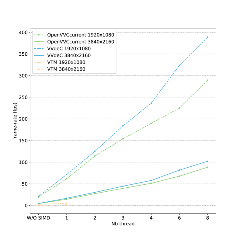
Fig. 9(a) presents the results in AI coding configuration in term of decoding frame-rate, expressed in fps. First, we will focus on mono-thread results. The points on the left correspond to mono-thread results without SIMD optimizations, and shows almost equivalent decoding speed for VVdeC and OpenVVC. Fig. 9(a) shows that the SIMD optimizations are slightly more efficient in OpenVVC compared to the two other software decoders. This is due to the specific effort dedicated to SIMD optimizations on intra prediction tools, as presented in Section III-D1. The performance is however still far from real-time since OpenVVC achieves an average frame-rates of 37 fps and 12 fps for FHD and UHD resolutions, respectively.
In order to explain multi-thread results, it is important to provide a reminder of the approaches in the different software decoders. In OpenVVC, frame level parallelism is enabled as presented in Section III-B. Since there are no MC dependencies between frames in AI configuration, each decoding thread is totally independent. For this reason, the frame-rate obtained by OpenVVC increases linearly with the number of threads in Fig. 9(a), reaching in average 249 fps and 75 fps for FHD and UHD resolutions, respectively. On the other hand, VVdeC relies on task level parallelism, introduced in Section II-B3. Data dependencies between decoding tasks exist in AI configuration, adding synchronization overhead between decoding threads. For this reason the frame-rates obtained with more than one thread with VVdeC software are lower compared to OpenVVC. In order to achieve 50 fps decoding of UHD resolution, VVdeC requires 6 threads in average, while OpenVVC only requires 4 threads.
IV-B2 Memory consumption
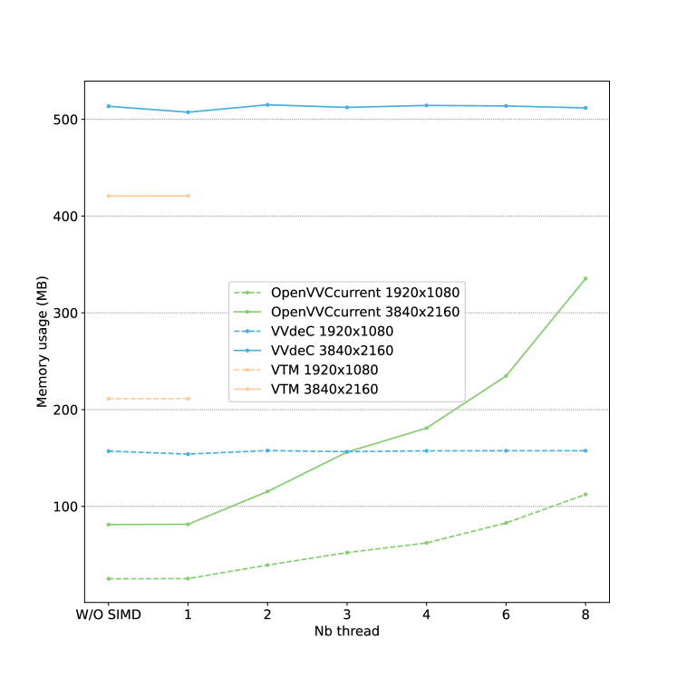
Fig. 9(b) presents the results in AI coding configuration in term of memory consumption, expressed in MB. With less than 115MB in average, OpenVVC is able to decode simultaneously up to 8 frames in FHD resolution and up to 2 frames of UHD resolution. However, VVdeC and VTM-16.2 decoders consume 510MB and 420MB, respectively, for the decoding of UHD resolution whatever the parallel setting (ie. number of threads). These numbers are 1.2 and 1.5 times higher compared to OpenVVC with 8 threads. As mentioned in Section II-B3, the memory consumption of these decoders is not optimized. However, it gives an order of magnitude of the very low memory consumption required by the proposed decoding approach in OpenVVC. This low memory is essentially due to the design of local structure (see Section III-C) and to the optimized management of the picture buffer pool described in Section III-B.
Second, Fig. 9(b) shows the linear increase of the memory consumption with the number of threads in OpenVVC. As mentioned in Section III-B, the integer dpb_max_nb_pic signals the maximum number of frames required in the DPB for the decoding of a sequence. In AI configuration, dpb_max_nb_pic is equal to 1. For frame level parallelism, a picture buffer and local buffers must be stored in addition per decoding thread, explaining the linear increase.
IV-C Comparison with SOTA under RA configuration
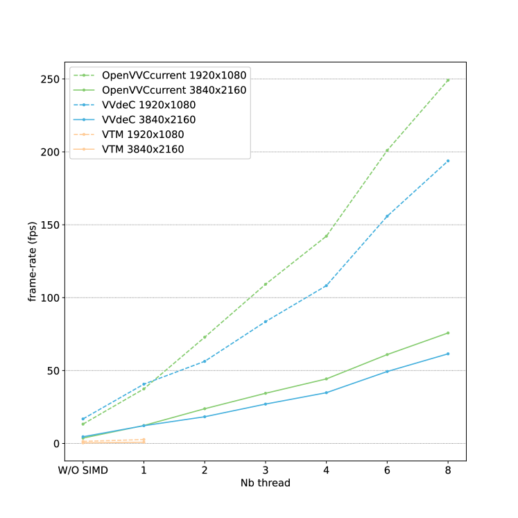
The experiments described in previous Section IV-B are also conducted in RA coding configuration. Fig. 10 presents the performance in RA coding configuration of the proposed OpenVVC decoder, compared to VTM-16.2 and VVdeC decoders, on FHD and UHD test sequences. As for Fig. 9, the results are averaged across the 4 QP values studied in this work. The dashed and continuous lines correspond to FHD and UHD resolutions, respectively.
IV-C1 Decoding performance
Fig. 10(a) presents the results in RA coding configuration in term of frame-rate, expressed in fps. Fig. 10(a) shows that the mono-thread results with SIMD optimizations obtained with OpenVVC are higher with almost a factor 2 compared to VTM-16.2 for both FHD and UHD contents. On the other hand, VVdeC achieves slightly better mono-thread results with SIMD compared to openVVC: 12% and 10% higher on average for FHD and UHD resolutions, respectively. In VVdeC, significant effort has been invested on data level parallelism, where a larger share of the inter tools are optimized with SIMD instructions compared to OpenVVC. This small gap will be filled in the future by extending SIMD optimizations to a larger share of the inter prediction tools, adding among other Geometric Partitioning Mode (GPM) and CIIP.
Fig. 10(a) also shows that OpenVVC green curves are not completely linear with the number of threads. Indeed, frame level parallelism in RA configuration is less efficient compared to AI configuration, due to MC synchronization overhead between frames. OpenVVC will achieve higher decoding speed by enabling tile level or task level parallelism in addition to frame level parallelism. The results obtained by OpenVVC in RA configuration are nonetheless very promising, since our decoder achieves live decoding FHD sequences beyond 60 fps with in average 2 decoding threads. For UHD content, picture rate of 50 fps is in average reached with 4 decoding threads.
IV-C2 Memory consumption
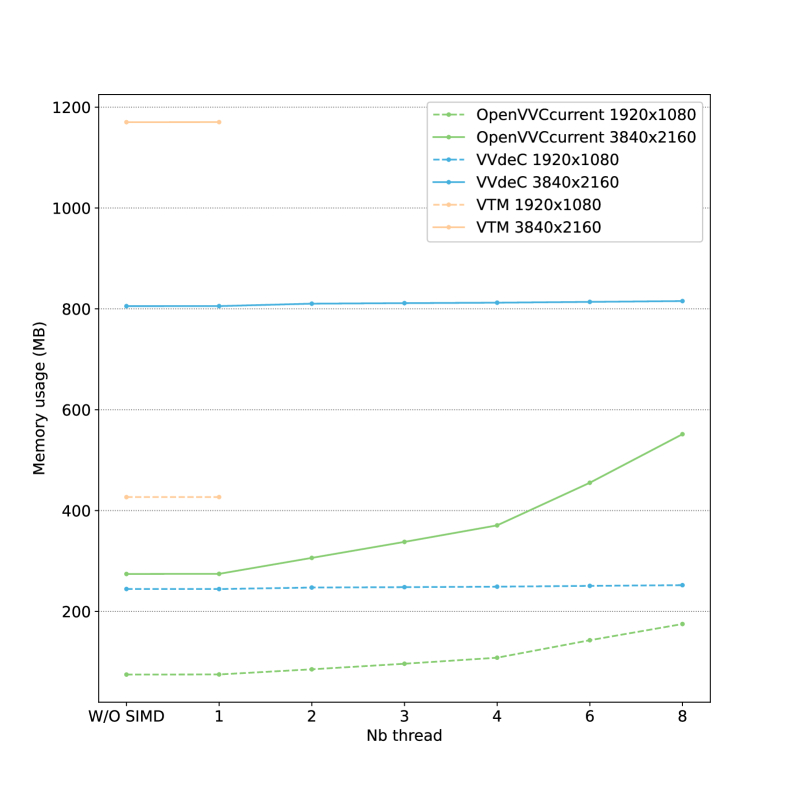
Fig. 10(b) presents the results in RA coding configuration in term of memory consumption, expressed in MB. In RA configuration, the maximum number of frames dpb_max_nb_pic required for the decoding of a sequence is in average equal to 7. TABLE I has shown that the picture buffer size is 8.3 MB and 33.2 MB for FHD and UHD resolutions, respectively. This explains the mono-thread memory consumption in OpenVVC of 60 MB ( MB) and 250 MB ( MB) in average for these resolutions. For frame level parallelism, a picture buffer and local buffers must be stored in addition per decoding thread, explaining the affine increase of memory consumption with the number of decoding threads.
Fig. 10(b) also highlights the very low memory consumption of OpenVVC in RA configuration compared to the VTM-16.2 and VVdeC software decoders. For mono-thread decoding, OpenVVC memory consumption is around 30% of theVVdeC memory in average. Even with 8 decoding threads, the memory consumption of our solution represents 65% of theVVdeC memory for UHD resolution.
IV-D Per-Sequence performance
FPS QP 27 QP 37 1 th. 4 th. Sp-up 1 th. 4 th. Sp-up HD FourPeople 75.8 288.5 3.8 113.6 441.2 3.9 Johnny 100.0 394.7 3.9 147.1 576.9 3.9 KristenAndSara 93.8 357.1 3.8 133.9 500.0 3.7 SlideEditing 56.7 211.1 3.7 74.5 271.4 3.6 SlideShow 126.0 450.0 3.6 161.5 572.7 3.5 Average 90.4 340.3 3.8 126.1 472.5 3.7 FHD ArenaOfValor 24.9 96.2 3.9 42.6 166.7 3.9 BasketballDrive 35.4 134.0 3.8 58.9 217.2 3.7 BQTerrace 26.4 101.4 3.8 47.2 178.6 3.8 Cactus 30.4 114.5 3.8 52.5 196.9 3.8 MarketPlace 35.5 133.9 3.8 58.1 227.3 3.9 RitualDance 39.9 150.0 3.8 63.0 241.9 3.8 Average 32.1 121.7 3.8 53.7 204.8 3.8 UHD Campfire 9.1 33.6 3.7 18.4 65.5 3.6 CatRobot1 11.2 40.9 3.6 16.7 59.4 3.5 DaylightRoad2 10.7 38.4 3.6 16.2 58.5 3.6 FoodMarket4 13.3 47.5 3.6 18.6 64.4 3.5 ParkRunning3 7.3 27.0 3.7 12.6 44.7 3.6 Tango2 15.3 56.1 3.7 20.2 74.0 3.7 Average 11.2 40.6 3.6 17.1 61.1 3.6
TABLE IV presents the decoding speed in AI configuration with 1 and 4 threads, according to the video sequence and QP value. The speed-up obtained with 4 threads is also displayed. For all the sequences, the decoding frame-rate increases with the QP value. Indeed, for QP 37 the bitstream size is in average divided by 2.5 compared to QP 27. It leads a considerable decrease in the decoding complexity due to the lower amount of symbols to process. The relation between the bitstream size and the decoding computational complexity has been studied in detail in [22].
At sequence level, TABLE IV shows that for a given QP value, resolution and number of threads, a high variance in the decoding speed exists according to the sequence characteristics. The clearest example is provided by the HD sequences, where the frame-rates of Johnny and KristenAndSara sequences are considerably higher compared to SlideEditing video. Indeed, SlideEditing displays screen content with complex spatial textures. It requires a higher number of symbols to be coded, compared to Johnny and KristenAndSara that display television talk shows with uniform background. The decoding speed disparities are also observable among FHD sequences, especially between RitualDance and ArenOfValor, and among UHD sequences, especially between Tango2 and ParkRunning3.
FPS QP 27 QP 37 1 th. 4 th. Sp-up 1 th. 4 th. Sp-up HD FourPeople 215.1 491.8 2.3 262.0 631.6 2.4 Johnny 229.9 582.5 2.5 252.1 705.9 2.8 KristenAndSara 218.2 526.3 2.4 237.2 645.2 2.7 SlideEditing 319.1 697.7 2.2 319.1 769.2 2.4 SlideShow 259.1 675.7 2.6 266.0 746.3 2.8 Average 248.3 594.8 2.4 267.3 699.6 2.6 FHD ArenaOfValor 64.4 179.6 2.8 87.6 262.0 3.0 BasketballDrive 52.0 162.3 3.1 62.8 209.2 3.3 BQTerrace 55.9 170.0 3.0 68.4 218.2 3.2 Cactus 66.0 201.6 3.1 88.5 277.8 3.1 MarketPlace 51.5 160.9 3.1 67.8 219.8 3.2 RitualDance 59.4 184.0 3.1 75.8 246.9 3.3 Average 58.2 176.4 3.0 75.1 239.0 3.2 UHD Campfire 15.8 54.9 3.5 19.5 69.0 3.5 CatRobot1 14.1 50.7 3.6 17.4 62.0 3.6 DaylightRoad2 13.2 46.8 3.6 16.2 57.5 3.5 FoodMarket4 14.0 50.4 3.6 16.5 59.4 3.6 ParkRunning3 9.4 33.0 3.5 12.2 44.8 3.7 Tango2 14.1 51.7 3.7 17.4 62.2 3.6 Average 13.4 47.9 3.6 16.5 59.1 3.6
FPS AI RA 1 th. 4 th. Sp-up 1 th. 4 th. Sp-up HD FourPeople 59.5 227.3 3.8 184.6 402.7 2.2 Johnny 78.1 300.0 3.8 196.7 480.0 2.4 KristenAndSara 74.3 288.5 3.9 176.5 416.7 2.4 SlideEditing 48.1 181.0 3.8 309.3 652.2 2.1 SlideShow 108.6 420.0 3.9 241.5 617.3 2.6 Average 73.7 283.3 3.8 221.7 513.8 2.3 FHD ArenaOfValor 18.7 72.1 3.9 51.9 140.5 2.7 BasketballDrive 22.1 82.9 3.8 43.0 127.2 3.0 BQTerrace 15.6 60.5 3.9 35.7 100.3 2.8 Cactus 18.7 71.6 3.8 51.4 151.1 2.9 MarketPlace 25.2 97.4 3.9 43.4 130.2 3.0 RitualDance 31.3 117.2 3.8 49.4 153.5 3.1 Average 21.9 83.6 3.8 45.8 133.8 2.9
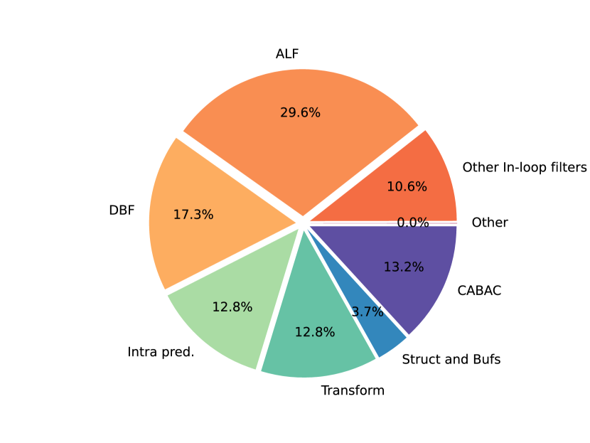
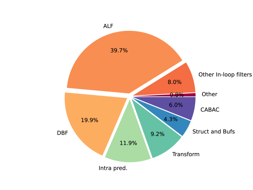
TABLE V presents the decoding speed obtained with OpenVVC in RA configuration according to the sequence and QP value. Many observations about the decoding speed disparities that were made in AI configuration also apply in RA configuration. Indeed, the decoding frame-rate increases with the QP value and the sequences previously mentioned with more complex spatial textures lead lower decoding speed also in RA configuration.
TABLE V points out the direct link between the speed-up obtained with 4 threads and the sequence resolution. Indeed, the speed-up variance is low among sequences with similar resolution, since it is contained in the short intervals , and for HD, FHD and UHD resolutions, respectively. These numbers show that the speed-up is considerably impacted by the resolution of the sequence. As explained in Section III-D2, the MC synchronization between decoding threads has been designed on a CTU line basis. For 128128 samples CTUs, a CTU line represents a 6th of a HD picture against a 17th of a UHD frame. Therefore, at least a 6th of the HD reference picture must be fully decoded before its data is used for MC. The interactions among decoding threads for MC synchronization will be higher, resulting in a lower speed-up compared to FHD and UHD resolutions.
Table VI gives the decoding frame rate of OpenVVC in both AI and RA configurations at high bitrate (QP=22). In this specific configuration, the decoding frame rate of FHD resolution with 4 threads is in average higher than 80 and 130 fps for AI and RA configurations, respectively.
IV-E Complexity distribution in OpenVVC
The decoding complexity distribution is obtained by running OpenVVC with Callgrind555Callgrind: http://valgrind.org/docs/manual/cl-manual.html.. Callgrind is the Valgrind profiling tool that records the call history of program functions as a call graph. By default, the data collected includes the number of instructions executed, the calling/callee relation among functions and the number of calls. In contrast to execution time, that depends among others on memory accesses or CPU frequency, the insight of the complexity distribution given by Callgrind is nearly constant regardless of the execution platform.
IV-F AI coding configuration
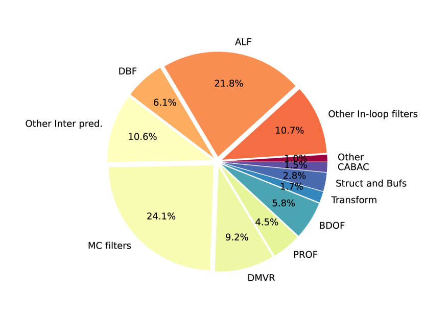
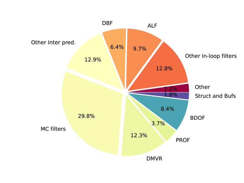
Fig. 11 shows the decoding complexity distribution of OpenVVC in AI coding configuration, for UHD test sequence CatRobot1 encoded at two QP values (Fig. 11(a) for QP27 and Fig. 11(b) for QP37). The results are shown under the form of pie charts, in % of total number of decoding instructions. The main decoding tasks displayed in Fig. 11 have been presented in Section II. The CABAC stage extracts from the bitstream the input data for all the other decoding stages. As mentioned in Section II-B1, the CABAC does not include significant data level parallelism and therefore is not accelerated with SIMD optimizations. It explains its relatively high share of the decoding complexity at QP27 (%). For QP 37, the bitstream size is in average divided by 2.5 compared to QP 27. It results in a considerable decrease in the CABAC complexity (%) due to the lower amount of symbols to process. The intra prediction stage includes among others the application of angular, DC and Planar modes, as well as alternative WAIP, MRL and MIP modes. The intra prediction stage represents around 12% of total complexity regardless the QP value. The transform stage in Fig. 11 computes the residual block through inverse quantization and inverse transform. It also includes the aggregation of the predicted block with the residual block. The transform stage is responsible for 12.8% and 9.2% of total complexity at QP 27 and QP 37, respectively. This difference is due to the transform skip mode, which is more selected by the encoder at high QPs. Four in-loop filters are performed on the reconstructed samples. They are displayed in shades of orange color in Fig. 11. The ALF provides a significant improvement in encoding efficiency [3]. However, in counterpart of the aforementioned benefits, ALF represents a considerable burden for the decoding process (29% and 39% according to the QP value). The DBF comes second with a share of over 17.3-19.9% of total decoding complexity. In total, the in-loop filters are responsible for over 50% of the decoding complexity in AI configuration. Finally, the operations on OpenVVC structures and buffers, presented in Sections III-B and III-C, represent 3.7-4.3% of OpenVVC complexity.
IV-G RA coding configuration
Fig. 12 shows the decoding complexity distribution of OpenVVC in RA coding configuration, for UHD test sequence CatRobot1 and according to the QP value (Fig. 12(a) for QP27 and Fig. 12(b) for QP37). It is important to note the lower share of the complexity required by the ALF in RA configuration (21.8% and 9.7%) compared to AI configuration. Indeed, the ALF is disabled on a large number of CTUs in RA configuration, which is not the case in AI configuration. In total, the sum of in-loop filters, CABAC, transform, intra prediction and internal buffers management represent 51% and 41% of the decoding complexity at QP27 and QP37, respectively. The remaining complexity is caused by the inter prediction tools, illustrated in shades of yellow color in the pie chart. The predominance of inter predicted frames in RA configuration explains this number, and also explains the very low portion of intra prediction in the pie charts. In VVC standard, the inter prediction stage enables various coding tools. As shown in Fig. 12, the most complex tools are the MC interpolation filters followed by Decoder-side Motion Vector Refinement (DMVR), Bi-Directional Optical Flow (BDOF) and Prediction Refinement with Optical Flow (PROF). Theses thee last tools require the application of the MC interpolation filters on the predicted block. For this reason, the complexity share of the MC interpolation filters is higher than 24% for both QP values.
To summarize, this section has identified two decoding stages as complexity bottlenecks for OpenVVC. The in-loop filtering stage is responsible for over 50% of the decoding complexity in AI configuration and the inter prediction stage is responsible for over 60% of the decoding complexity in RA configuration. In future works, the efforts for data and high level parallelism will therefore focus on these two decoding stages.
V Conclusion
In this paper, we presented openVVC, an open source software VVC decoder that supports a broad range of VVC tools. By combining extensive data level parallelism with frame level parallelism, OpenVVC achieves real-time decoding for UHD content. Considerable effort has been devoted to minimize both local and global buffer dimensions. As a consequence, the memory required by OpenVVC is remarkably low, which is a great advantage for its integration on embedded platforms with low memory ressources. Compared to other SOTA open source VVC decoders, OpenVVC achieves higher decoding speed than VVdeC and reference software VTM in AI configuration. In RA configuration, the small gap with VVdeC may be filled by implementing additional SIMD optimizations and by combining frame level parallelism with other high level parallelism techniques, such as tile or wavefront.
References
- [1] CISCO, “Global 2021 forecast highlights,” https://www.cisco.com/c/dam/m/en_us/solutions/service-provider/vni-forecast-highlights/pdf/Global_2021_Forecast_Highlights.pdf, p. 6, 2016.
- [2] Wassim Hamidouche, Thibaud Biatek, Mohsen Abdoli, Edouard Francois, Fernando Pescador, Milos Radosavljevic, Daniel Menard, and Mickael Raulet, “Versatile video coding standard: A review from coding tools to consumers deployment,” IEEE Consumer Electronics Magazine, pp. 1–1, 2022.
- [3] Benjamin Bross, Ye-Kui Wang, Yan Ye, Shan Liu, Jianle Chen, Gary J. Sullivan, and Jens-Rainer Ohm, “Overview of the versatile video coding (vvc) standard and its applications,” IEEE Transactions on Circuits and Systems for Video Technology, vol. 31, no. 10, pp. 3736–3764, 2021.
- [4] Charles Bonnineau, Wassim Hamidouche, Jérôme Fournier, Naty Sidaty, Jean-François Travers, and Olivier Déforges, “Perceptual quality assessment of hevc and vvc standards for 8k video,” IEEE Transactions on Broadcasting, pp. 1–8, 2022.
- [5] Naty Sidaty, Wassim Hamidouche, Olivier Deforges, Pierrick Philippe, and Jerome Fournier, “Compression Performance of the Versatile Video Coding: HD and UHD Visual Quality Monitoring,” in 2019 Picture Coding Symposium (PCS), Ningbo, China, Nov. 2019, pp. 1–5, IEEE.
- [6] Frank Bossen, Karsten Sühring, Adam Wieckowski, and Shan Liu, “Vvc complexity and software implementation analysis,” IEEE Transactions on Circuits and Systems for Video Technology, vol. 31, no. 10, pp. 3765–3778, 2021.
- [7] Alexandre Mercat, Arttu Makinen, Joose Sainio, Ari Lemmetti, Marko Viitanen, and Jarno Vanne, “Comparative Rate-Distortion-Complexity Analysis of VVC and HEVC Video Codecs,” IEEE Access, vol. 9, pp. 67813–67828, 2021.
- [8] Denis Engelhardt, Jan Moller, Jan Hahlbeck, and Benno Stabernack, “Fpga implementation of a full hd real-time hevc main profile decoder,” IEEE Transactions on Consumer Electronics, vol. 60, no. 3, pp. 476–484, 2014.
- [9] “VVC Reference Software Version 16.2,” https://vcgit.hhi.fraunhofer.de/jvet/VVCSoftware_VTM/-/tree/VTM-16.2, May 2022.
- [10] A. Wieckowski et al., “Update on open, optimized VVC implementations VVenC and VVdeC,” ISO/IEC JTC1/SC29/WG11 JVET document Y0136 (JVET-Y0136), Teleconference, January 2022.
- [11] “FFmpeg: Open Source and Cross-platform Multimedia Library,” http:// www.ffmpeg.org, Oct. 2020.
- [12] Benjamin Bross, Mauricio Alvarez-Mesa, Valeri George, Chi Ching Chi, Tobias Mayer, Ben Juurlink, and Thomas Schierl, “HEVC real-time decoding,” in Applications of Digital Image Processing XXXVI, Andrew G. Tescher, Ed. International Society for Optics and Photonics, 2013, vol. 8856, pp. 567 – 577, SPIE.
- [13] D. Marpe, H. Schwarz, and T. Wiegand, “Context-based adaptive binary arithmetic coding in the H.264/AVC video compression standard,” IEEE Transactions on Circuits and Systems for Video Technology, vol. 13, no. 7, pp. 620–636, July 2003.
- [14] Michael Schafer, Bjorn Stallenberger, Jonathan Pfaff, Philipp Helle, Heiko Schwarz, Detlev Marpe, and Thomas Wiegand, “Efficient Fixed-Point Implementation Of Matrix-Based Intra Prediction,” in 2020 IEEE International Conference on Image Processing (ICIP), Abu Dhabi, United Arab Emirates, Oct. 2020, pp. 3364–3368, IEEE.
- [15] Alexey Filippov and Vasily Rufitskiy, “Recent Advances in Intra Prediction for the Emerging H.266/VVC Video Coding Standard,” in 2019 International Multi-Conference on Engineering, Computer and Information Sciences (SIBIRCON), Novosibirsk, Russia, Oct. 2019, pp. 0525–0530, IEEE.
- [16] Taoran Lu, Fangjun Pu, Peng Yin, Sean McCarthy, Walt Husak, Tao Chen, Edouard Francois, Christophe Chevance, Franck Hiron, Jie Chen, Ru-Ling Liao, Yan Ye, and Jiancong Luo, “Luma Mapping with Chroma Scaling in Versatile Video Coding,” in 2020 Data Compression Conference (DCC), Snowbird, UT, USA, Mar. 2020, pp. 193–202, IEEE.
- [17] Andrey Norkin, Gisle Bjontegaard, Arild Fuldseth, Matthias Narroschke, Masaru Ikeda, Kenneth Andersson, Minhua Zhou, and Geert Van der Auwera, “HEVC Deblocking Filter,” IEEE Transactions on Circuits and Systems for Video Technology, vol. 22, no. 12, pp. 1746–1754, Dec. 2012.
- [18] Chih-Ming Fu, Elena Alshina, Alexander Alshin, Yu-Wen Huang, Ching-Yeh Chen, Chia-Yang Tsai, Chih-Wei Hsu, Shaw-Min Lei, Jeong-Hoon Park, and Woo-Jin Han, “Sample Adaptive Offset in the HEVC Standard,” IEEE Transactions on Circuits and Systems for Video Technology, vol. 22, no. 12, pp. 1755–1764, Dec. 2012.
- [19] Chia-Yang Tsai, Ching-Yeh Chen, Tomoo Yamakage, In Suk Chong, Yu-Wen Huang, Chih-Ming Fu, Takayuki Itoh, Takashi Watanabe, Takeshi Chujoh, Marta Karczewicz, and Shaw-Min Lei, “Adaptive Loop Filtering for Video Coding,” IEEE Journal of Selected Topics in Signal Processing, vol. 7, no. 6, pp. 934–945, Dec. 2013.
- [20] Kiran Misra, Frank Bossen, and Andrew Segall, “On Cross Component Adaptive Loop Filter for Video Compression,” in 2019 Picture Coding Symposium (PCS), Ningbo, China, Nov. 2019, pp. 1–5, IEEE.
- [21] Anup Saha, Miguel Chavarrías, Fernando Pescador, Ángel M. Groba, Kheyter Chassaigne, and Pedro L. Cebrián, “Complexity analysis of a versatile video coding decoder over embedded systems and general purpose processors,” Sensors, vol. 21, no. 10, 2021.
- [22] Hyunki Baik and Hwangjun Song, “A complexity-based adaptive tile partitioning algorithm for HEVC decoder parallelization,” in 2015 IEEE International Conference on Image Processing (ICIP), Quebec City, QC, Canada, Sept. 2015, pp. 4298–4302, IEEE.
- [23] Wassim Hamidouche, Mickael Raulet, and Olivier Deforges, “4K Real-Time and Parallel Software Video Decoder for Multilayer HEVC Extensions,” IEEE Transactions on Circuits and Systems for Video Technology, vol. 26, no. 1, pp. 169–180, Jan. 2016.
- [24] Chi Ching Chi, Mauricio Alvarez-Mesa, Benjamin Bross, Ben Juurlink, and Thomas Schierl, “SIMD Acceleration for HEVC Decoding,” IEEE Transactions on Circuits and Systems for Video Technology, vol. 25, no. 5, pp. 841–855, May 2015.
- [25] Leju Yan, Yizhou Duan, Jun Sun, and Zongming Guo, “Implementation of HEVC decoder on x86 processors with SIMD optimization,” in 2012 Visual Communications and Image Processing, San Diego, CA, USA, Nov. 2012, pp. 1–6, IEEE.
- [26] S. Thakkur and T. Huff, “Internet Streaming SIMD Extensions,” Computer, vol. 32, no. 12, pp. 26–34, Dec. 1999.
- [27] “AVX2 - Integer data types expanded to 256-bit SIMD,” https://software.intel.com/ content/ www/ us/en/develop /blogs/ haswell-new-instruction-descriptions-now-available.html, 2011.
- [28] “SSE2 Instructions,” https://docs.oracle.com/cd/E18752_01/html/817-5477/epmpv.html.
- [29] “Arm Neon Technology,” https://developer.arm.com/ architectures/ instruction-sets/ simd-isas/neon.
- [30] Erwan Raffin, Erwan Nogues, Wassim Hamidouche, Seppo Tomperi, Maxime Pelcat, and Daniel Menard, “Low power HEVC software decoder for mobile devices,” Journal of Real-Time Image Processing, vol. 12, no. 2, pp. 495–507, Aug. 2016.
- [31] Ye-Kui Wang, Robert Skupin, Miska M. Hannuksela, Sachin Deshpande, Hendry, Virginie Drugeon, Rickard Sjöberg, Byeongdoo Choi, Vadim Seregin, Yago Sanchez, Jill M. Boyce, Wade Wan, and Gary J. Sullivan, “The high-level syntax of the versatile video coding (vvc) standard,” IEEE Transactions on Circuits and Systems for Video Technology, vol. 31, no. 10, pp. 3779–3800, 2021.
- [32] Seehwan Yoo and Eun-Seok Ryu, “Parallel HEVC decoding with asymmetric mobile multicores,” Multimedia Tools and Applications, vol. 76, no. 16, pp. 17337–17352, Aug. 2017.
- [33] Chi Ching Chi, Mauricio Alvarez-Mesa, Ben Juurlink, Valeri George, and Thomas Schierl, “Improving the parallelization efficiency of HEVC decoding,” in 2012 19th IEEE International Conference on Image Processing, Orlando, FL, USA, Sept. 2012, pp. 213–216, IEEE.
- [34] Shaobo Zhang, Xiaoyun Zhang, and Zhiyong Gao, “Implementation and improvement of Wavefront Parallel Processing for HEVC encoding on many-core platform,” in 2014 IEEE International Conference on Multimedia and Expo Workshops (ICMEW), Chengdu, China, July 2014, pp. 1–6, IEEE.
- [35] Srinivas Gudumasu, Saurav Bandyopadhyay, and Yong He, “Software-based versatile video coding decoder parallelization,” in Proceedings of the 11th ACM Multimedia Systems Conference, Istanbul Turkey, May 2020, pp. 202–212, ACM.
- [36] P. Habermann, B. Juurlink, C. C. Chi, and M. Alvarez-Mesa, “Efficient Wavefront Parallel Processing for HEVC CABAC Decoding,” in 2020 28th Euromicro International Conference on Parallel, Distributed and Network-Based Processing (PDP), Västerås, Sweden, Mar. 2020, pp. 339–343, IEEE.
- [37] Adam Wieckowski, Gabriel Hege, Christian Bartnik, Christian Lehmann, Christian Stoffers, Benjamin Bross, and Detlev Marpe, “Towards A Live Software Decoder Implementation For The Upcoming Versatile Video Coding (VVC) Codec,” in 2020 IEEE International Conference on Image Processing (ICIP), Abu Dhabi, United Arab Emirates, Oct. 2020, pp. 3124–3128, IEEE.
- [38] Anand Meher Kotra, Mickael Raulet, and Olivier Deforges, “Comparison of different parallel implementations for deblocking filter of HEVC,” in 2013 IEEE International Conference on Acoustics, Speech and Signal Processing, Vancouver, BC, Canada, May 2013, pp. 2721–2725, IEEE.
- [39] Hyunho Jo, Donggyu Sim, and Byeungwoo Jeon, “Hybrid parallelization for HEVC decoder,” in 2013 6th International Congress on Image and Signal Processing (CISP), Hangzhou, China, Dec. 2013, pp. 170–175, IEEE.
- [40] Rafael Rodriguez-Sanchez and Enrique S. Quintana-Orti, “Tiles-and WPP-based HEVC Decoding on Asymmetric Multi-core Processors,” in 2017 IEEE Third International Conference on Multimedia Big Data (BigMM), Laguna Hills, CA, USA, Apr. 2017, pp. 299–302, IEEE.
- [41] “Tencent O266dec decoder library,” https://github.com/ TencentCloud/ O266player, 2020.
- [42] Bin Zhu, Shan Liu, Yuan Liu, Yi Luo, Jing Ye, Haiyan Xu, Ying Huang, Hualong Jiao, Xiaozhong Xu, Xianguo Zhang, and Chenchen Gu, “A Real-Time H.266/VVC Software Decoder,” in 2021 IEEE International Conference on Multimedia and Expo (ICME), Shenzhen, China, July 2021, pp. 1–6, IEEE.
- [43] Cisco, “Global Internet adoption and devices and connection,” https://www.cisco.com/c/en/us/solutions/collateral/executive-perspectives/annual-internet-report/white-paper-c11-741490.html, 2018.
- [44] Yiming Li, Shan Liu, Yu Chen, Yushan Zheng, Sijia Chen, Bin Zhu, and Jian Lou, “An optimized h.266/vvc software decoder on mobile platform,” in 2021 Picture Coding Symposium (PCS), 2021, pp. 1–5.
- [45] Sullivan Gary, “Deployment status of the VVC standard,” ISO/IEC JTC1/SC29/WG11 JVET document Y0021 (JVET-Y0021), Teleconference, January 2022.
- [46] F. Pescador, J. P. Caño, M. J. Garrido, E. Juarez, and M. Raulet, “A dsp hevc decoder implementation based on openhevc,” in 2014 IEEE International Conference on Consumer Electronics (ICCE), 2014, pp. 61–62.
- [47] Jean Le Feuvre, Cyril Concolato, and Jean-Claude Moissinac, “GPAC: open source multimedia framework,” in Proceedings of the 15th international conference on Multimedia - MULTIMEDIA ’07, Augsburg, Germany, 2007, p. 1009, ACM Press.
- [48] Jill Boyce, Karsten Suehring, and Xiang Li, “JVET common test conditions and software reference configurations,” ISO/IEC JTC1/SC29/WG11 JVET document J1010 (JVET-J1010), San Diego, USA, April 2018.