Autonomous Driving From the Sky:
Design and End-to-End Performance Evaluation
Abstract
For autonomous vehicles to operate without human intervention, information sharing from local sensors plays a fundamental role. This can be challenging to handle with bandwidth-constrained communication systems, which calls for the adoption of new wireless technologies, like in the millimeter wave (mmWave) bands, to solve capacity issues. Another approach is to exploit Unmanned Aerial Vehicles (UAVs), able to provide human users and their cars with an aerial bird’s-eye view of the scene otherwise unavailable, thus offering broader and more centralized observations. In this article we combine both aspects and design a novel framework in which UAVs, operating at mmWaves, broadcast sensory information to the ground as a means to extend the (local) perception range of vehicles. To do so, we conduct a full-stack end-to-end simulation campaign with ns-3 considering real UAV data from the Stanford Drone Dataset, and study four scenarios representing different UAV-to-ground communication strategies. Our results focus on the trade-off between centralized data processing in the sky vs. distributed local processing on the ground, with considerations related to the throughput, latency and reliability of the communication process.
Index Terms:
UAV s, vehicular networks, millimeter waves, offloading, end-to-end performance, ns-3.I Introduction
The scientific community is witnessing an increasing interest in research and experimentation on autonomous driving vehicles, powered by the several benefits they provide (from improved safety to more efficient traffic management) and the market potential they generate [1].
For future vehicles to be fully autonomous, they will be equipped with diverse and heterogeneous sensors, from optical cameras to Light Detection and Ranging (LiDAR) sensors, able to perceive the environment and identify road entities in the surroundings [2]. In this scenario, more robust scene understanding can be achieved if vehicles share sensory data with other vehicles, which however imposes strict demands in terms of data rates, that may be difficult to support with legacy bandwidth-constrained communication systems [3]. One way to solve this issue is to compress and process the data before transmission [4], as well as to operate at high frequencies, e.g., in the millimeter wave (mmWave) bands, where the large spectrum available, in combination with Multiple Input Multiple Output (MIMO) technologies, can support ultra-high transmission rates [5].
At the same time, Unmanned Aerial Vehicles (UAVs), mainly known as drones, have rapidly became popular thanks to the ease of deployment, low maintenance and operating costs, and native support for ubiquitous broadband coverage. When equipped with sensors, UAVs can enable several services, from crowd monitoring [6] to airspace surveillance and border patrol [7]. Drones have been further studied as a solution to provide connectivity to ground users and first responders in emergency situations [8], e.g., when cellular infrastructures are unavailable or no longer operational [9].
In recent years, UAVs have been also considered to support autonomous driving applications, especially for vehicular edge computing [10] and traffic management [11]. In fact, UAVs operating from the sky can guarantee a birds’-eye wide perception of the scene than it would be possible from vehicles’ (local) sensor acquisitions, thus achieving more centralized and precise observations. Despite these benefits, however, the limited battery power and computational capacity available at the UAVs raise the questions of where to process and how to disseminate sensory data on the ground, in view of latency constraints. Today, UAV communication is typically enabled by legacy wireless technologies such as Long Term Evolution (LTE) [12] which, however, may not satisfy the boldest latency and throughput requirements of future vehicular networks. In this respect, several prior works have demonstrated the feasibility of operating UAVs at mmWaves [13], and characterized the optimal beamforming and deployment options for aerial nodes [14].
Based on the above introduction, in this paper we evaluate the feasibility of implementing an autonomous driving framework by relying on UAV’s observations, and whether sensory information from the sky can be efficiently delivered to ground vehicles, possibly operating at mmWaves. To do so, we investigate several communication options between the UAV and the vehicles, each of which involves three main components: a UAV where sensory data are generated, a base station (BS) acting as a relay, and multiple autonomous vehicles. Notably, we study whether autonomous driving tasks based on these data (e.g., object detection) should be processed on board of the UAV, or delegated to on-the-ground nodes. The performance of the different schemes will be evaluated in ns-3 using the mmwave module [15] and real-world UAV data collected in the Stanford Drone Dataset [16], which promotes extreme levels of realism and permits to analyze the network considering full-stack end-to-end metrics and a real-world dataset as input. Our preliminary results demonstrate that data processing at the BS guarantees more efficient communication, in view of the limited power and computational capabilities of the UAV.
The rest of this paper is organized as follows. In Sec. II we review the most recent works on UAV-based autonomous driving research, in Sec. III we present our system model and communication scenarios, in Sec. IV we describe how we extended Network Simulator 3 (ns-3) to simulate UAV-to-ground communication, in Sec. V we present our main numerical results, whereas conclusions are summarized in Sec. VI.
II State of the art
In this section, we discuss the recent research in the area of UAV-based autonomous driving, specifically computational offloading and data dissemination. Hayat et al., in [17], evaluate the burden of data (image) processing for UAV autonomous navigation, that can be done on board, or fully/partially offloaded to an edge server. Similarly, in [18] the authors study the performance of UAV edge computing using Hydra, an architecture for the establishment of flexible sensing-analysis-control pipelines over autonomous airborne systems.
If cellular infrastructures are unavailable (e.g., damaged by natural disasters), data offloading can be also between ground vehicles, whose limited computing and energy resources make it difficult to execute computationally sensitive mobile applications on board, and aerial platforms. In [19], the author suggest to offload computing tasks from the ground to UAVs that carry edge serves, and propose an algorithm to minimize the total energy and time required for the UAVs to complete the offloaded tasks, while optimizing their 3D flying height and horizontal positions. Computational offloading may be also assisted by high altitude platforms (HAPs), as proposed in [20], where the authors designed a framework to offload communication and computational resources to aerial nodes to maximize the total number of user device requests with satisfied delay requirements while minimizing the total energy consumption. Similarly, in our prior work [10], we formalized an optimization problem in which tasks are modeled as a Poisson arrival process, and applied queuing theory to identify how ground vehicles should offload resource-hungry tasks to UAVs, HAPs, or a combination of the two.
With respect to the state of the art, in this paper we do not focus on computational offloading, but rather on how UAV data are disseminated to ground vehicles, and where to process them. Moreover, while most literature focuses on UAV-to-ground communication in the legacy bands, and/or considers link-level evaluations, we perform end-to-end simulations in ns-3 considering mmWave frequencies, as well as both on-board and fully-offloaded computation.
III UAV-to-Ground Communication Scenarios
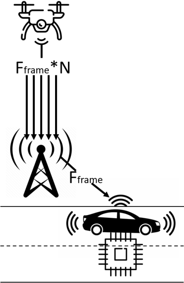
In this section we present four possible strategies for UAV-to-ground communication, as illustrated in Fig. 1(a). Notably, each scenario consists of the following elements: a UAV that is recording videos from the sky, autonomous cars on the ground, and a BS (or gNB, in 5G NR parlance) forwarding data from the UAV to the cars. The UAV is placed at the center of the scene (e.g., at a road intersection) at height , the BS is placed on the ground, perpendicular to the UAV in order to maintain a stable connection, and vehicles are allocated randomly within a rectangle.
The four models differ in the way the data are broadcast, and the location of the computing platform (the chip icon in Fig. 1(a)) where UAV sensory data is processed to detect critical road entities in the scene.
Scenario 1 — Multiple full frames (MFF)
In the first scenario (Fig. 1(a)) the drone is sending frames via the BS at a rate to each ground vehicle, that will eventually perform object detection using its own on-board computational capacity. The frame rate is not optimized so, in a situation where all packets are delivered without errors (best-case scenario), the total frame rate in the first link (UAV-BS) would be equal to , i.e., the sum of the frames sent in each second link (BS-vehicle). On the downside, computation on board of vehicles may incur non-negligible delays given the limited capacity of budget vehicles, and the data rate in the first link would be times larger than the total data rate of each second link. In turn, this approach does not require coordination with the BS.
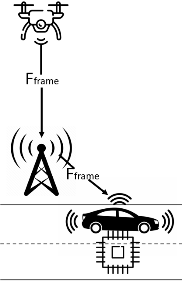
Scenario 2 — Broadcast full frames (BFF)
In the second scenario (Fig. 1(b)), frames are sent at an optimized rate. While in the MFF scenario sensory data in the first link were replicated times, with optimized settings the UAV sends only one frame to the BS, that will create copies of the received packets and eventually forward them to each of the cars. Finally, each vehicle will perform object detection on the received data, which may still incur long delays due to computational limitations. Ideally, the throughput in the first link would be equal to the throughput of each second link. In other words, the ideal throughput of the first link is times smaller than the sum of the throughput of all the second links.
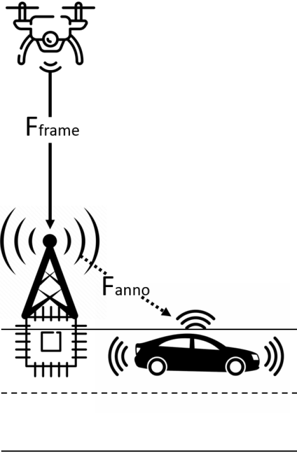
Scenario 3 — Broadcast frames and annotations (BFA)
In the third scenario (Fig. 1(c)) the UAV sends one copy of all the frames to the BS, which then performs object detection on the received data. This approach promotes faster processing than in the previous scenarios, as BSs are typically connected to continuous power sources and do not pose strict limitations in terms of computational capacity, space and storage. Eventually, the processed output (i.e., the bounding boxes of the detected objects, also referred to as annotations) is returned to the ground vehicles at a frame rate , in a packet of a much smaller size than the original frame, which allows to reduce the communication latency on the second links. In particular, the size of an annotation is calculated as , where is the memory size of a bounding box and is the number of detected objects. To find the value of , we made offline simulations to generate bounding boxes from real-world UAV video recordings collected in the Stanford Drone Dataset [16]. To do so, we used the YoloV5 algorithm [21], a common benchmark in this field.
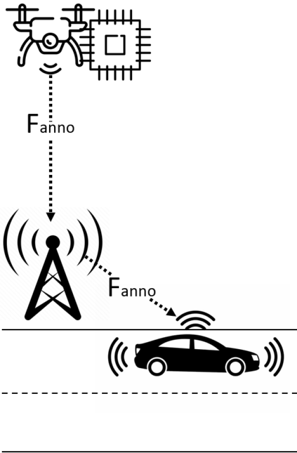
Scenario 4 — Broadcast annotations only (BAO)
In the fourth scenario (Fig. 1(d)), object detection is performed as soon as the frame is generated, i.e., on board of the UAV. While this allows low-size annotations to be sent already on the first link, as well as on the second link, thereby reducing the overall communication latency, the computational capacity of aerial nodes is generally lower than that available at the BSs, which may increase the processing delay compared to the BFA scenario. Ideally, the per-user throughput in the first link is equal to the per-user throughput in each second link.
IV ns-3 Implementation
In this section we describe how we extended the ns-3 simulator to implement the four communication scenarios presented in Sec. III. While most simulators focus on Physical (PHY) and Medium Access Control (MAC) layer designs, and sacrifice the accuracy of the higher layers to reduce the computational complexity, ns-3 incorporates accurate models of the whole protocol stack, thus enabling scalable end-to-end simulations. In particular, in our work communication nodes operate at mmWaves. As such, we use the ns3-mmwave module, described in [15], which enables the simulation of 5G-NR-compliant end-to-end cellular networks at mmWave frequencies. It features a complete stack for User Equipments (UEs) and gNBs, with custom PHY (described in [22]) and MAC layers with an Orthogonal Frequency Division Multiplexing (OFDM) frame structure, dynamic Time Division Duplexing (TDD), Adaptive Modulation and Coding (AMC), and several scheduler implementations. Thanks to the integration with ns-3, it also features a complete implementation of the User Datagram Protocol (UDP) stack. The simulator also features a 3GPP-compliant channel model, as well as antenna and beamforming models for mmWave communications [23].
In terms of the implementation, in the MFF scenario UDP is installed at the end vehicles: the UAV is set up as a client while vehicles as servers. With this configuration, the UAV sends the same amount of packets to every car. On the other hand, to implement broadcast communications in the other scenarios, some changes were applied to the ns3-mmwave module that manages the forwarding of the packets at the BS. With these changes, the UAV is sending only one copy of each packet to the BS, that in turn produces copies of the received packet, which are transmitted to the vehicles on the ground.
Finally, the packet size and the packet sending rate are set. For the simulations where the size of a UAV frame is larger than the maximum size of a UDP packet (UDPpck), the data must be split and sent in smaller packets of size UDPpck. In MFF and BFF and in the first link of BFA, the packets sending rate is equal to where is the total size in Byte of the sensory frame to be sent, and is the source frame rate. For the second link in BFA, and in BAO, the annotation rate is .
V Performance evaluation
In this section we introduce our performance evaluation setup, and discuss the simulation performance of the different UAV-to-ground communication scenarios.
| Parameter | Value |
| Carrier frequency | 28 GHz |
| Bandwidth | 1 GHz |
| BS TX power | 30 dBm |
| UAV TX power | 30 dBm |
| RLC buffer size | 10 MB |
| Frame rate | FPS |
| Frame size | See Fig. 2 |
| Number of UEs | |
| Simulation time | 15s |
V-A Simulation Parameters
Our simulator implements the communication scenarios described in Sec. III. The main parameters for the simulations are described in Table I. We also provide the source code and simulation scripts as a reference.111https://bitbucket.org/mat_bord/autonomous-driving-from-the-sky We run the simulations with the ns-3 Simulation Execution Manager (SEM) library [24], which takes care of running multiple statistically independent instances of the same scenario and collecting relevant metrics. The ns-3 simulation time is set to 15 s, and we consider the following parameters:
-
•
Application frame rate. According to the Stanford Drone Dataset, the camera of the UAV records at frames per second (FPS). Therefore, we set the frame rate of the ns-3 application generating UAV data to (independently on weather annotations or full frames are transmitted).
-
•
Number of vehicles (). It corresponds to the number of objects detected in each frame of the Stanford Drone Dataset videos, and sets the number of vehicles in each simulation. Based on offline simulations, we obtained that each processed frame featured from 4 to 21 vehicles, as shown in Fig. 2.
-
•
Full frame size. It is the size of a frame of the Stanford Drone Dataset videos to be sent from the UAV, as shown in Fig. 2. Notice that the frame size does not follow an increasing trend with the number of vehicles in the scene, i.e., the size of each full frame does not necessarily correlate with the number of vehicles.
-
•
Annotation size . It is the size of an annotation produced after object detection. It is modeled as , where bytes is the average size of a single bounding box detected by the YoloV5 detection algorithm [21], and is the number of vehicles in the scene.
We consider 90 random UAV frames from the Stanford Drone Dataset, and run multiple statistically independent simulations to capture the following end-to-end metrics:
-
•
Per-user throughput. It corresponds to the total number of received bytes per user divided by the total simulation time, averaged over all connected vehicles.
-
•
Per-user reliability. It is measured as the ratio between the number of packets delivered to the cars without errors and the total number of packets transmitted by the UAV.
-
•
Per-user latency. It is modeled as , where represents the latency between the UAV and the BS (uplink) and represents the latency between the BS and the vehicles (downlink), averaged over all connected vehicles. Both and account for the transmission time as well as the queuing time resulting from NR-specific scheduling and buffering, as modeled in the ns3-mmwave module.
V-B Performance Evaluation
In the following paragraphs we compare the performance of the different communication scenarios described in Sec. III. Fig. 3 reports the end-to-end throughput, latency and reliability for all configurations.
MFF scenario. The results in Fig. 3 clearly highlight that the wireless network (despite a bandwidth of 1 GHz) cannot support MFF with more than 11 vehicles and 30 FPS. Notably, the throughput (Fig. 3(a)) and reliability (Fig. 3(c)) decrease, while the latency (Fig. 3(b)) increases to more than 200 ms. This is due to the a bottleneck in the first link (UAV-BS), which transmits times more data compared to each second link (BS-car). Notice that the latency of the second link is not particularly representative, as it is relative to only the correctly received packets. Given that most packet losses happen on the first link, which makes the system less congested, the (few) packets that make it to the second link are then transmitted with very low latency. This also explains the latency plateau at around 200 ms, due to the fact that the UAV transmit buffer (e.g., at the Radio Link Control (RLC) layer) overflows for more than 11 cars.
On the other hand, the MFF configuration can better support an application generating data at 15 FPS, as a consequence of the 50% less traffic on the UAV-BS link, and the resulting less populated RLC queues at the UAV. The system performance is stable for up to 19 vehicles (Fig. 3(a)). After this threshold the UAV buffer saturates causing a degradation in latency (which reaches the 200 ms plateau) and reliability.
BFF scenario. The BFF strategy is more efficient than MFF, as it does not saturate the UAV buffer and the capacity of the first link by avoiding unnecessary duplication of the frames in the uplink. The performance of BFF with an application rate of 30 FPS only degrades for more than 20 connected vehicles. Unlike MFF, this is due to a saturation of resources in the downlink, i.e., in the second links from the BS to the end vehicles. In fact, Fig. 2 shows that the file size of a frame with few users (e.g., 4) is comparable with the file size of a frame with 21 users. In the first case, however, the resources on the wireless link are split only among the UAV (uplink) and 4 more users (downlink), while in the latter more than 20 users contend for the same downlink resources, which may saturate the available capacity. BFF also easily sustains the performance with 15 FPS at the application.
This strategy, while being more efficient than MFF, requires the support for multicasting support at the RAN, a feature that has been only recently standardized in 5G networks [25, 26].
BFA scenario. BFA, which assumes data processing at the BS and the transmission of annotations in the downlink, manages to easily support the traffic for all the users in the tested environment. Fig. 3(c) and Fig. 3(b) show that this scheme provides ultra-high reliability, with an average of 98.472% correctly delivered annotations, and an end-to-end latency as low as 3 ms, respectively. In this case, the performance with 30 and 15 FPS is comparable. Notice that the BFA throughput is reasonably lower than that of MFF and BFF. This is due to the much lower size of annotations compared to full frames (on average up to 4 orders of magnitude), which limits the source rate on the second link.
In Fig. 4 we plot the average per-user latency in the uplink , i.e., the UAV-BS link, and in the downlink , i.e., the BS-car links. We can see that in BFA the throughput in the uplink, where full frames are transmitted, is higher than the throughput in the downlink. Nonetheless, the latency is lower in the first link. This can be explained by considering the resource scheduling process implemented in the simulated 5G BS. As discussed in Sec. IV, this follows a TDD scheme, where the resources are first split between the uplink and the downlink, and then assigned to each uplink or downlink user. In this case, the UAV is the only uplink user – thus it does not have to contend for resources with other users. Additionally, to accommodate for the analog beamforming implemented at the BS to improve the link budget with the vehicles at mmWaves, each symbol at the PHY layer is allocated to a single user at a time. This further deteriorates the contention performance in the downlink, and results into lower efficiency (in the resource allocation) with higher latency. Future developments can try to address this by using different scheduler implementations, frequency range (which does not require beamforming), or hybrid beamforming schemes [27].
BAO scenario. In this case we assume data processing at the UAV, and the transmission of only annotations (with a size proportional to the number of vehicles) in the two links. While the throughput is as low as 0.208 Mbit/s (0.104 Mbit/s) for 30 (15) FPS, as expected, the reliability increases with respect to BFA to 99.66% for 30 FPS and 99.88% for 15 FPS. The latency is 2.922 ms on average for both 30 and 15 FPS, regardless of the number of vehicles in the scenario.
Overall end-to-end comparison. This analysis clearly highlights that throughput should not be the only metric used to profile the performance of data dissemination systems in the context of vehicular networks. A more important metric, which is independent of the application source rate, is indeed the end-to-end reliability, which indicates (in this case) how many frames or annotations are received correctly. The throughput analysis then can provide inputs on what kind of dissemination strategy a certain wireless network (in this case, a 5G mmWave deployment) can support. In Fig. 3(a) the highest throughput is obtained in the BFF scenario with 30 FPS, where the UAV is sending only one copy of each frame in the first link and then the BS is broadcasting the received information to each connected vehicle. However, with more than 20 users the latency drastically increases (Fig. 3(b)) and the reliability decreases (Fig. 3(c)). The scenarios that are transmitting only annotations (BFA only in the downlink, BAO in both uplink and downlink) have the highest reliability and the lowest latency overall. Moreover, in both scenarios, the information that each car is receiving is the same, but in one case the object detection has to be performed by the BS while in the other it has to be performed by the UAV. On one side, the UAV has generally more energy and computational constraints than the BS, which makes BOA more desirable. On the other side, BFA may be the only available choice in those environments lacking coverage from terrestrial infrastructures [28]. Further studies on power consumption will help understand what is the final choice for UAV-to-ground communication, depending on whether it is feasible to perform object detection at the UAV.
VI Conclusions
In this paper we presented and evaluated different communication techniques between UAV s and ground vehicles for the dissemination of UAV sensory observations to augment vehicles’ autonomous driving capabilities, based on high-capacity mmWave links. We assessed the performance of four different communication scenarios, with applications transmitting data at 15 and 30 FPS with UDP at the transport layer. An extensive performance evaluation based on real-world UAV data and considering ns-3 simulations showed that those configurations that transmit annotations (rather than full frames) achieve the best performance in terms of latency and reliability. For up to 21 connected users, they guarantee a latency of around 2 ms, and a reliability above 99%. Our results provide a first, quantitative evaluation of the feasibility of complementing vehicle’s on-board sensors with UAV data from the sky.
As part of our future work, we will combine the communication network model with an energy model that profiles the computational complexity of the object detection task on the UAV, BS, and ground vehicles hardware.
References
- [1] L. M. Clements and K. M. Kockelman, “Economic effects of automated vehicles,” Transportation Research Record, vol. 2606, pp. 106–114, 2017.
- [2] V. Rossi, P. Testolina, M. Giordani, and M. Zorzi, “On the Role of Sensor Fusion for Object Detection in Future Vehicular Networks,” in Joint European Conference on Networks and Communications 6G Summit (EuCNC/6G Summit), 2021.
- [3] M. Giordani, A. Zanella, T. Higuchi, O. Altintas, and M. Zorzi, “On the Feasibility of Integrating mmWave and IEEE 802.11p for V2V Communications,” IEEE Connected and Automated Vehicles Symposium (CAVS), Aug 2018.
- [4] F. Nardo, D. Peressoni, P. Testolina, M. Giordani, and A. Zanella, “Point Cloud Compression for Autonomous Driving: A Performance Comparison,” in IEEE Wireless Communications and Networking Conference (WCNC), Feb 2022.
- [5] T. Zugno, M. Drago, M. Giordani, M. Polese, and M. Zorzi, “Toward Standardization of Millimeter-Wave Vehicle-to-Vehicle Networks: Open Challenges and Performance Evaluation,” IEEE Communications Magazine, vol. 58, no. 9, pp. 79–85, Sep 2020.
- [6] P. Chandhar and E. G. Larsson, “Massive MIMO for Connectivity With Drones: Case Studies and Future Directions,” IEEE Access, vol. 7, pp. 94 676–94 691, July 2019.
- [7] P. Chandhar, D. Danev, and E. G. Larsson, “Massive MIMO for Communications With Drone Swarms,” IEEE Transactions on Wireless Communications, vol. 17, no. 3, pp. 1604–1629, March 2018.
- [8] W. Shi, H. Zhou, J. Li, W. Xu, N. Zhang, and X. Shen, “Drone Assisted Vehicular Networks: Architecture, Challenges and Opportunities,” IEEE Network, vol. 32, no. 3, pp. 130–137, May 2018.
- [9] M. Mezzavilla, M. Polese, A. Zanella, A. Dhananjay, S. Rangan, C. Kessler, T. S. Rappaport, and M. Zorzi, “Public Safety Communications above 6 GHz: Challenges and Opportunities,” IEEE Access, vol. 6, pp. 316–329, Nov 2018.
- [10] A. Traspadini, M. Giordani, and M. Zorzi, “UAV/HAP-Assisted Vehicular Edge Computing in 6G: Where and What to Offload?” Joint European Conference on Networks and Communications 6G Summit (EuCNC/6G Summit), 2022.
- [11] R. Lu, R. Zhang, X. Cheng, and L. Yang, “UAV-Assisted Data Dissemination with Proactive Caching and File Sharing in V2X Networks,” in IEEE Global Communications Conference (GLOBECOM), 2019.
- [12] B. Van Der Bergh, A. Chiumento, and S. Pollin, “LTE in the sky: trading off propagation benefits with interference costs for aerial nodes,” IEEE Communications Magazine, vol. 54, no. 5, pp. 44–50, May 2016.
- [13] L. Zhang, H. Zhao, S. Hou, Z. Zhao, H. Xu, X. Wu, Q. Wu, and R. Zhang, “A Survey on 5G Millimeter Wave Communications for UAV-Assisted Wireless Networks,” IEEE Access, vol. 7, pp. 117 460–117 504, July 2019.
- [14] Y. Wang, M. Giordani, X. Wen, and M. Zorzi, “On the beamforming design of millimeter wave UAV networks: Power vs. capacity trade-offs,” Computer Networks, p. 108746, Jan 2022.
- [15] M. Mezzavilla, M. Zhang, M. Polese, R. Ford, S. Dutta, S. Rangan, and M. Zorzi, “End-to-End Simulation of 5G mmWave Networks,” IEEE Communications Surveys Tutorials, vol. 20, no. 3, pp. 2237–2263, ThirdQuarter 2018.
- [16] A. Robicquet, A. Sadeghian, A. Alahi, and S. Savarese, “Learning social etiquette: Human trajectory understanding in crowded scenes,” in European Conference on Computer Vision (ECCV), 2016, pp. 549–565.
- [17] S. Hayat, R. Jung, H. Hellwagner, C. Bettstetter, D. Emini, and D. Schnieders, “Edge Computing in 5G for Drone Navigation: What to Offload?” IEEE Robotics and Automation Letters, vol. 6, pp. 2571–2578, April 2021.
- [18] D. Callegaro, S. Baidya, and M. Levorato, “A Measurement Study on Edge Computing for Autonomous UAVs,” in Proceedings of the ACM SIGCOMM Workshop on Mobile AirGround Edge Computing, Systems, Networks, and Applications, 2019.
- [19] S. Sun, G. Zhang, H. Mei, K. Wang, and K. Yang, “Optimizing Multi-UAV Deployment in 3-D Space to Minimize Task Completion Time in UAV-Enabled Mobile Edge Computing Systems,” IEEE Communications Letters, vol. 25, no. 2, pp. 579–583, Feb 2021.
- [20] D. S. Lakew, A.-T. Tran, N.-N. Dao, and S. Cho, “Intelligent Offloading and Resource Allocation in HAP-Assisted MEC Networks,” in International Conference on Information and Communication Technology Convergence (ICTC), Oct 2021, pp. 1582–1587.
- [21] X. Zhu, S. Lyu, X. Wang, and Q. Zhao, “TPH-YOLOv5: Improved YOLOv5 Based on Transformer Prediction Head for Object Detection on Drone-captured Scenarios,” in Proceedings of the IEEE/CVF International Conference on Computer Vision, 2021, pp. 2778–2788.
- [22] S. Dutta, M. Mezzavilla, R. Ford, M. Zhang, S. Rangan, and M. Zorzi, “Frame Structure Design and Analysis for Millimeter Wave Cellular Systems,” IEEE Transactions on Wireless Communications, vol. 16, no. 3, pp. 1508–1522, March 2017.
- [23] T. Zugno, M. Polese, N. Patriciello, B. Bojović, S. Lagen, and M. Zorzi, “Implementation of a spatial channel model for ns-3,” in Proceedings of the 2020 Workshop on ns-3, 2020.
- [24] D. Magrin, D. Zhou, and M. Zorzi, “A simulation execution manager for ns-3: Encouraging reproducibility and simplifying statistical analysis of ns-3 simulations,” in Proceedings of the 22nd International ACM Conference on Modeling, Analysis and Simulation of Wireless and Mobile Systems, 2019.
- [25] G. Araniti, M. Condoluci, P. Scopelliti, A. Molinaro, and A. Iera, “Multicasting over Emerging 5G Networks: Challenges and Perspectives,” IEEE Network, vol. 31, no. 2, pp. 80–89, March 2017.
- [26] Q. Zeng, S. Li, and J. Song, “Field Test for 5G NR Multicast and Broadcast Services,” in 2021 International Conference on Electrical Engineering and Photonics (EExPolytech), Oct 2021.
- [27] F. Gómez-Cuba, T. Zugno, J. Kim, M. Polese, S. Bahk, and M. Zorzi, “Hybrid Beamforming in 5G mmWave Networks: A Full-Stack Perspective,” IEEE Transactions on Wireless Communications, vol. 21, no. 2, pp. 1288–1303, Feb 2022.
- [28] A. Chaoub, M. Giordani, B. Lall, V. Bhatia, A. Kliks, L. Mendes, K. Rabie, H. Saarnisaari, A. Singhal, N. Zhang, S. Dixit, and M. Zorzi, “6G for Bridging the Digital Divide: Wireless Connectivity to Remote Areas,” IEEE Wireless Communications, vol. 29, no. 1, pp. 160–168, July 2021.