Galvanic Corrosion and Electric Field in Lithium Anode Passivation Films: Effects on Self-Discharge
Abstract
Battery interfaces help govern rate capability, safety/stability, cycle life, and self-discharge, but significant gaps remain in our understanding at atomic length scales that can be exploited to improve interfacial properties. In particular, Li partially plated on copper current collectors, relevant to the anodeless, lithium metal cell which is a holy grail of high density energy battery research, has recently been reported to undergo galvanic corrosion and exhibit short shelf lives. We apply large scale Density Functional Theory (DFT) calculations and X-ray photoelectron spectroscopy to examine the reaction between the electrolyte and LiCu junctions coated with uniform, thin electrolyte interphase (SEI) passivating films at two applied voltages. The DFT galvanic corrosion calculations show that electrolyte degradation preferentially occurs on Li-plated regions and should lead to thicker SEI films. We find similarities but also fundamental differences between traditional metal localized pitting and Li-corrosion mechanisms due to overpotential and ionic diffusion rate disparities in the two cases. Furthermore, using the recently proposed, highly reactive lithium hydride (LiH) component SEI as example, we distinguish between electrochemical and chemical degradation pathways which are partially responsible for self-discharge, with the chemical pathway found to exhibit slow kinetics. We also predict that electric fields should in general exist across natural SEI components like LiH, and across artificial SEI films like LiI and LiAlO2 often applied to improve battery cycling. Underlying and unifying these predictions is a framework of DFT voltage/overpotential definitions which we have derived from electrochemistry disciplines like structural metal corrosion studies; our analysis can only be made using the correct electronic voltage definitions.
I Introduction
Lithium (Li) metal anodes represent one of the holy grails of battery research because of its high gravimetric capacity advantage.intro So far, high coulombic efficiencycycling remains an elusive goal, especially in liquid electrolyte-based batteries which are our focus. Recently self-discharge,selfdischarge ; mengsd ; cuisd ; galvanic1 ; galvanic2 ; merrill ; galvanic3 whereby the stored energy in a battery dissipates without generating a current in the external circuit, has been identified as another potential issue, especially in anodes with three-dimensional architectures.galvanic2 Fast self-discharge has been attributed to “galvanic corrosion” which occurs in lithium (Li) plated on copper (Cu) current collectors. Vastly different self-discharge rates have been reported,cuisd ; galvanic1 ; galvanic2 ; merrill depending on the amount of Li plated; the degree of self-discharge reversibility also varies. This is surprising because Cu current collectors are widely used, and are usually in contact with Li on one side and the electrolyte on the other side, yet galvanic corrosion has seldom been noted.
The lithium galvanic corrosion phenomenon offers a unique opportunity for comparison between traditional (e.g., localized pitting) metal corrosioncorrbook and degradation in lithium battery electrodes.pccp ; kostecki Metals like aluminum (Al) have low reduction potentials that lie outside the electrolyte (e.g., water) stability window, and has to be passivated with native oxide films. Galvanic processes occur when a more electropositive metal is in contact, leading to transfer from and enhanced dissolution of the less electronegative metal.jced These aspects have profound similarities with Li metal and other Li-battery anodespccp which are metastable against most electrolytes and are always passivated by solid electrolyte interphase (SEI) films.xu2004 ; qi_review ; vegge ; canepa Even if Li is scraped clean in a glove box, it is “dirty” in that it immediately getters any oxygen or water in the atmosphere and forms a oxide coating to passivate itself (supporting information document, S.I., Sec. S1). In many cases the SEI film is generated by electrochemical reduction of the electrolyte during plating, and/or by subsequent chemical reactions of the initial SEI or electrolyte with the plated lithium metal.xu2004 ; sei ; qi_review In other cases, artificial SEIs (aSEIs) are coated directly on Li metal, or first on the current collector prior to Li plating,kozen ; elam to improve cycling and self-discharge behavior via improvement of SEI passivation properties or anode morphology. Artificial passivation is also used to protect structural metals from corrosion.corrbook Other links between traditional corrosion research and battery studies include stress corrosion crackingsjharris and current collector degradation.curtiss
There are also fundamental differences between batteries and Al/steel-corrosion, so much so that very notions of “galvanic corrosion,” and even “corrosion,” in a Li anode context need to be re-examined. For example, Al and steel pitting onset occurs when the passivating oxide films break down, partly because of the slow metal cation diffusion rates in the oxide. Hence the anodic Al oxidation step is corrosion-limiting, and this is accelerated at higher voltages. Modeling of corrosion of structural corrosion is challenging because corrosion usually involves overpotentials against metal plating (e.g., the mininum Al pitting potential is -0.5 V vs. SHE,pittingvoltage much higher than the -1.66 V vs. SHE of Al3+ + 3 Al(s)), spatial segregation of cathodic and anodic processes, and kinetics (not only thermodynamic) considerations.corrbook Li+ diffusion is sufficiently fast in its SEI that overpotentials are less relevant, and that cathodic reactions (electrolyte reduction), accelerated at low voltages, might be limiting; we will use DFT and measurements to demonstrate this point. Despite these caveats, we propose that synergistic studies of metal corrosion mitigation and lithium anode protection will yield significant, cross-cutting benefits to both fields.
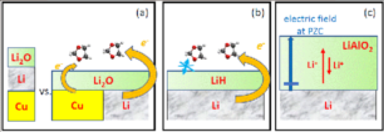
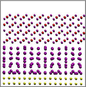
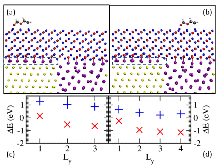
We hypothesize that galvanic corrosion-like effects in Li anodes occur due to quasi-three-point phase boundaries between the Cu current collector, the plated Li, and the electrolyte – with the electrolyte separated from the two metals by a nascent SEI. In this work, we use DFT slab models with up to 3000 atoms (sizes almost unprecedented in previous battery studies) we investigate CuLi metal junctions at the nanoscale. 50 % and 100% coverages of Cu-current collector by lithium metal are considered (Fig. 1a). Here we exploit a previous established framework in the use of Density Functional Theory (DFT) to model battery interfaces.pccp These advances are based on electrochemical modeling paradigms often developed outside of battery research;pccp ; otani ; peterson ; iceland ; mira ; dabo1 ; marzari ; filhol ; pham have been applied to model Al-corrosion;corrosion include electrochemical voltage/overpotential definitions; and reveal complexities like electric fieldmaier and contact potentialpccp ; gb ; corrosion ; marks effects seldom addressed in the battery modeling literature. They go far beyond thermodynamics/phase diagram analysis of interfacial stability, although the latter approach is important too.wolve ; siegel ; vdv ; ceder1 ; islam1 ; phase By computing work functions and modeling electrochemical reduction reactions of solvent molecules, we demonstrate the critical role played by spatial inhomogeneity. Solvent decomposition consumes Li metal atoms and ultimately turn them into Li+. This consumes Li inventory and leads to irreversible losses and self-discharge.
We focus on the fundamental chemistry and physics of solid-solid interfaces associated with thin-film coated (“dirty”) battery electrodes. The nascent, uniformly-thick SEI films in our models are thin enough that they are not considered final structures, but can still grow and evolve. This allows us to concentrate on intermediate stage SEI growth and evolutionevolve1 ; evolve2 ; evolve3 ; evolve4 on top of native or engineeredgallant1 oxides generally present on Li metal anodes, unlike prevalent modeling work on pristine Li(s)/liquid electrolyte interfaces mostly relevant to the initial stages of SEI growth.schmickler ; qi_review ; note0 ; highconc ; highconc2 ; wise ; nasa ; baskin ; lii We also refrain from making a priori assumptions about our model systems reaching equilibrium between electronic and ionic properties, unlike previous work which do not address overpotentials.gerischer ; swift DFT time scales are short compared to experiments (Supporting Information, SI Sec. S6) which can lead to unintentional overpotentials.pccp We match possible or experimentally-determined overpotential values during self-discharge/corrosion to DFT (electronic) voltages by tuning the interfacial structure. In other words, we focus on voltage-function relations, not structure-function relations which are less pertinent because atomic length-scale experimental interfacial structures have seldom been elucidated. Kinetics considerations are addressed using both explicit reaction barrier calculations, and separation-of-time-scale approximations.
Understanding the chemical and electrochemical stability of SEI film components and their reactions with the electrolyte is also relevant to predicting Li “corrosion” processes. Our DFT framework and electronic voltage definitionspccp also permit us to distinguish electrochemical vs. chemical electrolyte degradation reactions, both of which can contribute to self-discharge. (Here “chemical” refers to reactions that can occur without an electron source, and includes both energetic and kinetic considerations.) To this end, we adopt as a test case the reactive lithium hydride (LiH), which has surprisingly been reported to exist in the SEI.lih1 ; lih2 ; lih3 We hypothesize that LiH, which is thermodynamically unstable against water, oxygen, and most organic compounds, must exhibit kinetically-limited reactions in order to persist and be observed in the SEI (Fig. 1b).
Our work on LiH reveals other complexities that can potentially be exploited to reduce self-discharge. The contact potential between LiH and Li metal is significantly lower than that between Li metal and well-known SEI components LiF or Li2O.pccp This leads us to survey other materials like LiI and LiAlO2 which have been proposed as aSEI materials,lii ; jacs ; elam ; kozen and which reveal an even wider range of contact potential values. Since the contact potential plus mathetmatical integration of the electric field across the SEI and electrolyte add up to the applied potential,pccp this implies that different field strengths must exist inside different SEI/aSEI films at a given voltage. The fact that battery electrode interfaces have surface charges and exert electric fields should be expected because many electrified interfaces only exhibit one “potential of zero charge” (PZC) and should have net charges away from the PZC; neverthless electric fields in the SEI have mostly been neglected until recently.maier ; filhol ; pccp We illustrate this using cross-film Li+ transport in LiAlO2 coated on Li metal (Fig. 1c), and propose that interfacial electric field engineering will have beneficial properties.yada ; ye2021 Our models represent no-current snapshots of SEI growthmaier and/or Li self-discharge,galvanic1 ; galvanic2 ; merrill not the entire dynamic “corrosion” process. Nevertheless, they illustrate useful new concepts that should motivate future experiment work.
II Computational Methods
II.1 DFT Details
All DFT calculations are conducted under T=0 K ultrahigh vacuum (UHV) conditions, using periodically replicated simulation cells and the Vienna Atomic Simulation Package (VASP) version 5.3.vasp1 ; vasp1a ; vasp2 ; vasp3 A 400 eV planewave energy cutoff and a 10-4 eV convergence criterion are enforced. Most calculations apply the Perdew-Burke-Ernzerhof (PBE) functional.pbe In the S.I., HSE06 is used for spot checks.hse06a ; hse06b ; hse06c The standard dipole correction is applied.dipole It eliminates spurious coupling between periodic images in the -direction. However, no standard correction currently exists for dipole/dipole-image interactions in the - plane; the consequences will be discussed below. Transition state energies or barriers are computed using the climbing image nudged elastic band method.neb
The two- and multilayer SEI modelsaurbach_two_layer ; li_dual_layer ; shinoda suggest that inorganic products coat the active anode material, separating it from the thicker, amorphous, and porous organic/polymeric layer outside. More recently, cryogenic transmission electron microcopy (cryo-TEM) images suggest an amorphous matrix in contact with Li metal, in which Li2O and LiF nanoparticles are embedded in some electrolytes.meng ; cui ; jungjohann While the chemical identity of the armophous phase has not been revealed by TEM, candidates that are stable against Li metal are extremely limited.batt A recent demonstration of reactions between Li2CO3 and Li metal surfaces suggests this matrix may contain graphitic carbon with Li intercalated arising from multistep electrochemical reduction of organic electrolyte and their intermediate products, including Li2CO3.umd Since graphitic carbon is metallic and does not block , here we focus on Li2Ogallant1 ; shinoda and other insulating inorganic SEI products as the inner SEI layer (S.I. Sec. S1). The organic SEI outside the inorganic SEI has complex, heterogeneous compositions and structure, and likely exhibits a low dielectric constant. As before,pccp ; gb we approximate the outer organic SEI as a vacuum. Our implicit assumption is that, to first order, all the electric fields and voltage drops are contained within the inorganic SEI (or aSEI). To the extent that the low dielectric constant organic SEI is common to all interfacial systems considered in this work, its effects on DOL reactivity on different Li2O-covered surfaces should largely cancel. Organic SEI and liquid electrolyte effects will be investigated in future work.otani Due to the approximations used in this work (thickness of material slabs, finite DFT accuracy, omission of organic SEI and electrolyte regions), the properties predicted are semi-quantitative. However, the well-defined approximations in our models provide a path towards future systematic improvements.
Regarding bulk inorganic SEI/aSEI component crystal structures, we obtain a 4.013 Å lattice constant in the 4 formula unit, cubic LiH unit cell. The (001) and (110) facets are found to exhibit surface energies of 0.33 and 0.74 J/m2, respectively. Henceforth we focus on (001). LiI has a similar cubic structure, and a 6.025 Å cubic unit with 4 formula units. The 4-formula unit LiAlO2 unit cell has 5.306.354.96 Å3 dimensions.jacs
The lowest energy Li surface, Li(001), is adopted. The initial registries at the interfaces are selected as follows. (Here “registry” refers to how the surface unit cells of the two materials are aligned or spatially offset in the - plane.) LiI, Li2O, and LiH exhibit weak interactions with Li metal surfaces (although the contact potential can still be large); the precise registry is not critical, and only one choice each is used. Unless otherwise noted, one Li atom is inserted directly below each anion on the inner surface of the inorganic films (i.e., I- in LiI, O2- in Li2O, and H- in LiH). This Li “interlayer” has been found to lower the electronic voltage (, Eq. 2 below) and is either thermoneutral or exothermic at some interfaces, after subtracting the Li metal cohesive energy (i.e., 0 V, Eq. 1 below).gb Other details of the interface models are given in Table S3 (S.I.). When doubling or quadrupling simulation cells for system size convergence purposes, we start from the converged configurations of the baseline cells (S.I. Table S3).
For LiAlO2, where a significant binding energy with Li metal is expected, we have attempted a different procedure. We displace the Li metal slab against the oxide in a - grid of increment 0.5 Å, optimize the configurations, and select the most stable of the 81 resulting registries. The computed standard deviation in interfacial energy is 0.02 J/m2. After this grid search, it is necessary to further conduct ab initio molecular dynamics (AIMD) T=450 K for 9 ps, followed by a quench from T=450 K to T=50 K over 4 ps and then an energy minimzation calculation, to obtain the final Li/LiAlO2 configuration. Without AIMD annealing, the introduction of Li-vacancies, needed to model Li diffusion energies, leads to very significant reconstructions at the interface. Experimentally, aSEI/Li(s) interfaces are in many cases created by first forming the aSEI on Cu and then plating Li metal underneath the aSEI. How much of this room temperature process is qualitatively consistent with our “cold press,” “light annealing” short AIMD trajectory approach will be considered in future work.
The LiCu junction is first optimized as a 10.1636.00 Å simulation cell with a Cu352Li195 stoichiometry and two metal-vacuum interfaces in the direction. The optimal is found to be 34.17 Å. Then the Li2O (111) oxide is place on top of it while straining the oxide and metal slabs in the - plane to fit their average surface supercell dimensions. The optimization technique used herein locates local minima, not the globally most favorable configuration. We do not observe Li/Cu alloying.
II.2 Voltages and Electric Fields
Li anodes emit and consume both ions and electrons, so two voltage definitions can be introduced. We define the ionic voltage, asvoltage_prb
| (1) |
where is the total energy of the simulation cell with an electrode with M atoms, is the M chemical potential in its bulk metal phase, and is the electronic charge. is the energy of inserting an Li atom at the most favorable Li-insertion site, referenced to Li metal cohesion energy, divided by . The electronic voltage is
| (2) |
where =-) is the work function, is the vacuum levels in the same simulation cell in which the Fermi level is computed, and 1.37 V is related to the Trassati relation,trasatti adapted to the Li+/Li(s) reference. Physically, is to be compared with the voltage measured or controlled using potentiostats, with necessary caveats about the different time scales involved in DFT and experimental overpotentials given in the S.I. (Sec. S6). depends on the -point sampling and material slab thicknesses, and reported values herein are precise to 0.1 V. We stress that and values are referenced to Li+/Li(s).
and are altered by the effective dipole moment in the surface film and at material interfaces via
| (3) |
Here is the surface density of a uniform point dipole sheet, is the average dipole magnitude, and atomic units are used. We define as the electric field across the insulating film, not including the contact potential.
“-equilibrium” is said to be established when =. When , is offset by the “overpotential” value from and is away from -equilibrium. In this sense, is not an independent “prediction”; it should be treated as a constraint, pegged to experimentally determined potentials or overpotentials. Overpotentials are generally determined by processes too slow for DFT to predict.
We also define a local electrostatic potential (or local vacuum level) , obtained by integrating over the 3-dimensional electrostatic potential
| (4) |
Here is the cell dimension in the direction, and and bracket the vacuum region in the slab between 3.0 Å and 6.0 Å above the mean position of the top atomic layer of the slabs. This is a qualitative guide to the tendency of electron transfer to a range of values roughly commensurate with the size of an adsorbed atom. is not physical or measurable. Only relative values of are relevant.
Within ground state DFT, each metal, metal alloy, and metal junction slab has a single , and hence a unique , even if local variations in can occur.gb In DFT slabs, there can be two per metal slab because the front and back sides (coated with surface films or not) can have different vacuum levels which are split by the artifial dipole sheet that keeps the vacuum free of electric fields.dipole We only report on the side of the coated Li slab, unless otherwise stated.
We consider models in which nascent passive films of thickness 15 Å exist on metal surfaces. This thickness should still allow electron leakage through the film.gb2 Hence we do not consider Marcus theory for long-range transfer,jacs ; gb2 ; marcus1 ; marcus2 ; miller or non-adiabatic effects.marcus3 Finally, there are fundamental disconnects between the battery and other electrohemical computational literature concerning voltage definitions and electric fields/electric double layers (EDL), at the interfaces of both liquid and solid electrolytes.corrosion ; pccp ; maier ; voltage_prb ; borodin ; latz ; tateyama ; tateyama2 ; janek ; macdonald81 ; field1 ; field2 ; gewirth ; aizawa ; luntz ; liang2018 ; qi The S.I. (Sec. S5) attempts to reconcile different viewpoints.
III Results and Discussions
III.1 DOL Reductive Decomposition on Coated Li Metal
(a) 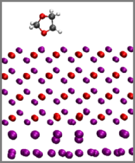
 (b)
(b)
(c) 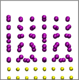
 (d)
(d)
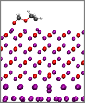
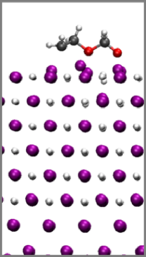
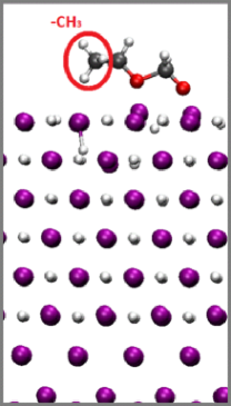
To demonstrate the basic science and DFT system size effects involved, we first consider the reaction of 1,3-dioxolane (DOL) on pure Li2O-coated Li metal surfaces. DOL is a cyclic ether frequently used as a co-solvent in Li metal anode batteries.dol1 It is chosen as the sole adsorbed solvent for computational convenience; its ring structure requires less exploration of the configuration space than linear molecules like 1,2-dimethoxyethane (DME). In the S.I. (Sec. S4), we estimate that the DOL reduction potential in the electrolyte is below 0.0 V vs. Li+/Li(s). This suggests that DOL electrochemical reduction most likely initiates on the electrode surface, where transfer to DOL should be more favored via surface stabilization effects. Note that the electrolyte anion is in fact more readily reduced than the ether solvent, although organic SEI components are also found (S.I. Sec. S1). The higher anion reactivity makes it more difficult to distinguish effects in our proof-of-principle calculations, and DOL is chosen instead. In the following we focus on concerted electron transfer and DOL decomposition reaction on inorganic SEI surfaces; the DOL is assumed to be embedded in the low-dielectric organic SEI, not the solvent. We do not focus on its reduction potential, only the initial DOL bonding-breaking event. The chemical constituent of DOL-based SEI has not yet been completely elucidated.kang_dft ; bal_dol Thus, DOL is meant as a stand-in for the organic SEI in addition to representing the solvent.
In Fig. 2, a 10 Å thick Li2O (111) layer covers the Li (001) surface,gb giving 0.05 V vs. Li+/Li(s) (Table 1),gb ; pccp which is very close to the Li plating potential. Fig. 2a-b depict an intact and a decomposed DOL on a 10 Å thick Li2O film on the Li (001) metal surface. Bader charge analysisbader reveals that the DOL with one broken bond is doubly reduced. Table 1 shows that, in the largest simulation cell considered, the energy released is =-1.72 eV, while the reaction barrier is =+0.67 eV, in reasonable agreement with the 0.6 eV computed in liquid using a different DFT method.kang_dft The latter translates into a sub-second reaction time scale using standard kinetic equations with a 1012/s prefactor.pccp As battery interfaces are usually governed by kinetics, not thermodynmics, is more significant than as long as the converged exhibits 0 (exothermic reaction).
Next we discuss the convergence of and with system size. Adsorption of an intact DOL does not entail transfer and should not change significantly. For the decomposed DOL, the two transfer from Li metal to the molecule leads to an artificial increase of the dipole moment in the charge-neutral simulation cell, and a significant increase in (Eq. 2-3). Thus , defined as the difference in between the slabs with decomposed and intact DOL, is a measure of system size dependence; it should converge to zero in the limit of infinite system size. can be as large as 2.08 V in slabs with small lateral dimenions (Table 1). As the cell size increases, drops to 0.14 V. Simultaneously, increases in magnitude from -0.85 eV in a 11 cell (17.09.9 Å2 lateral area, S.I. Table S3) to -1.72 eV in a 22 cell (34.119.7 Å2, 1427 atoms). In the largest cell, has apparently converged to within 0.17 eV. is more costly to compute than . Fortunately, the transition state associated involves the transfer of 2 from the metal to the DOL, and the convergence of with respect to system size is faster than for (Table 1).
We also consider this DOL reaction in the absence of the Li metal underneath the Li2O layer by removing the Li slab and re-optimizing. The atomic configurations look similar to those in Fig. 2a-b and are not shown. jumps to +2.43 eV. This suggests that, without an source, DOL decomposition reaction does not occur, unless other processes, such as cation-induced polymerization of DOL, occur. Another configuration where the dangling CH2 group reacts with a surface O-atom on Li2O slabs without a Li metal slab underneath, and thus do not involve transfer from Li metal, is energetically but not kinetically favorable, and is not shown in Fig. 2. See the SI Sec. S9 for details. As another point of reference, on pristine Li (001) surfaces, DOL readily breaks one C-O bond to release =-3.67 eV with a barrier of =0.74 eV (S.I. Sec. S4); even more energy is released during subsequent DOL bond-breaking events. However, as we have stressed, pristine Li metal is too reactive to exist in batteries (S.I. Sec. S1). These calculations do not involve transfer across an insulating oxide film and should not incur large system size effects.pccp
(g) (h)
III.2 CuLi Junction: Work Function
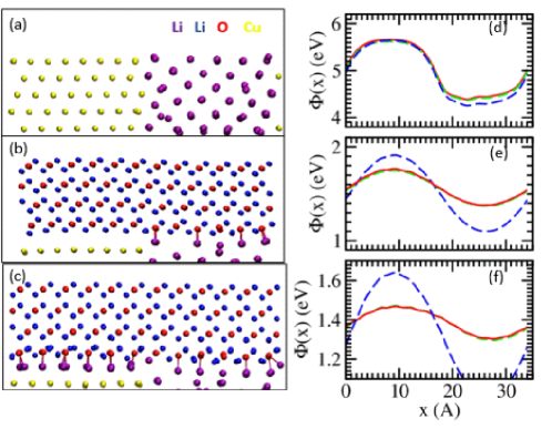
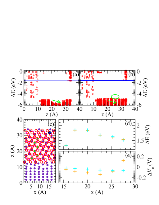
The above discussion lays the ground work for examining DOL electrochemical reduction on the LiCu junction. Here we report the computational results and defer discussions of relevance to corrosion to the next subsection. First we distinguish two types of junctions. Fig. 2c depicts a layer of Li (001) covering Cu (001). This model mimics complete Li-plating on a Cu current collector. In contrast, Fig. 3a depicts a junction between Li and Cu metal in the direction. It mimics partial, 50 %, Li plating on a Cu current collector.
For the Fig. 2c configuration, the work functions on the Li and Cu sides of the simulation cells are 3.01 eV and 4.48 eV, which translate into =1.63 V and =3.11 V, respectively. These values are similar to those of pure Li and Cu metals with such facets; the 0.1 eV discrepancy with published resultsgb is due to the thinness of the slabs and the small strain on the Cu, lattice matched to Li. The similarity with bare Li and Cu is in this case expected because electrostatic screening length is on the order of Angstroms within metals, and the effect of the junction should be screened out. The existence of two vacuum level is a DFT artifact,dipole and should be interpreted as follows. The exposed Li and Cu surfaces are electrically disconnected; they can be tuned to a common via modifying their independent EDL’s. Fig. 2d further depicts a Li2O (111) slab coating the Li (001) surface on Cu(111). This system exhibits =0.05 V, similar to the value for the Li (001)/Li2O (111) interface in the absence of the Cu slab (Fig. 2a, without DOL).
Next we consider the horizontal LiCu junction (Fig. 3). In ground state DFT, a metal should exhibit a single and a unique . Nevertheless, spatial heterogeneity is manifested in the local electrostatic potential in Fig. 3d-f, which is a qualitative guide, not a measurable quantity. For the Fig. 3a configuration, , which suggests how favored local ejection is, has a maximum in the Cu region and a mininum in the Li region that differ by 1.26 eV (Fig. 3d). This should translate into a 1.26 V “local potential” difference within 3-6 Å of the surface where instantaneous electrochemical reactions are concerned. If the two metallic regions were completely disconnected in the direction, we expect would be related to pure Li and pure Cu vacuum level DFT/PBE values, which are 3.01 eV and 4.88 eV (see above), yielding a 1.87 eV difference. transfer from Li to Cu has evidently reduced this difference, but the Li side of the LiCu junction remains more electronegative than the Cu side within a few Å of the metal surface.
Note that the 1.26 eV is obtained using a simulation cell with -dimensions of 40 Å and 50 Å. The default 28 Å -dimension cell (Table S1, S.I.), which has a smaller vacuum region, yields a larger peak-to-value difference of 1.40 eV. The convergence of is thus slower than the work function itself, which is well converged with a -dimension of 28 Å.
An uncoated electrode is unrealistic in battery settings. Next, we put a 10 Å-thick Li2O layer on the metal and optimize the atomic configuration (Fig. 3b, henceforth the “oxide 1” model). We predict =0.85 V for this system. Joining Cu with Li has therefore raised by 0.80 V relative to Fig. 2a. At 0 V, the Li metal is metastable; however, the simulation cell lacks a liquid electrolyte that can accommodate Li+ or a simulation time scale needed for dissolution to occur, and the Li slab remains. The difference between the Cu-maximum and the Li-minimum is reduced to 0.39 eV in the simulation cells with the largest vacuum region (Fig. 3e), but remains significant.
Finally, we find that adding 14 additional “interlayer” Li atoms beneath the Li2O film on the Cu side (Table S3 in the S.I.), with each Li directly coordinated to a O anion at the interface, lowers to 0.01 V,gb which is almost at -equilibrium (==0.0 V, Fig. 3c). (Again, is well converged with respect to the -dimension of the the simulation cell; increasing the cell size by 14 Å reduces only by 0.03 V; henceforth we report the 0.01 V value.) This model is referred to as “oxide 2.” We stress that, for this model, we have managed to change significantly by only altering the contact potential (SI Sec. S11);gb ; pccp ; marks this solid-state degree of freedom at Li-battery interfaces, arising from the perhaps unique mobility of Li+, is missing at the interface of uncoated electrodes,otani ; filhol but cannot be neglected in batteries. The average binding energy of the 14 added Li atoms, offset by the Li metal cohesive energy, is a favorable -0.57 eV, consistent with =0.57 V assuming that these are the most favorable available Li-sites. In other words, Li insertion into these interface sites is thermodynamically favorable at or below 0.57 V, although we have not examined all possible Li configurations, and the estimated is approximate. Creation of this interlayer should occur when the instantaneous voltage is =0.01 V (Fig. 3c) when the interlayer is thermodynamically favored, but not at 0.85 V (Fig. 3b). Strictly speaking, adding 18 Li at the interface is found to be most consistent with =0.0 V, but this yields =-0.16 V (SI Sec. S10). Here we neglect this slight discrepancy in . Oxide 1 and 2 models are approximate, self-consistent depictions of the system at two different applied voltages at time scales before Li from the Li metal can diffuse; oxide 2 conforms to our definition of -equilibrium. Interlayer Li atoms have significantly less effects on the Li side.gb After adding these Li atoms to the Cu side, the maximum variation in is further lowered to 0.16 eV, (Fig. 3f), but still persists.
Fig. 3d-f emphasize the existence of spatial electrostatic heterogeneity on metal electrode surfaces. Local voltage variation of up to 0.3 V during charge has been measured for graphite anodes.mukherjee This variation has been entirely attributed to kinetic limitations/ohmic losses; our predictions suggest that structural origins may also need to be explored.
III.3 Interpretations of CuLi Junction Work Functions
Our calculations show that a 100% Li2O(111)-coated Li(001) slab (Fig. 2a without a DOL) exhibits a similar work function as the same composite slab deposited on Cu (001) (Fig. 2d). This suggests that, on copper current collectors completely covered with plated Li metal (Fig. 2c-d), and therefore without a electrolyte/Li/Cu 3-phase junction, the Li/Cu contact has no effect on electron transfer. Hence galvanic corrosion should not occur. This inference is consistent with Ref. galvanic2, and merrill, .
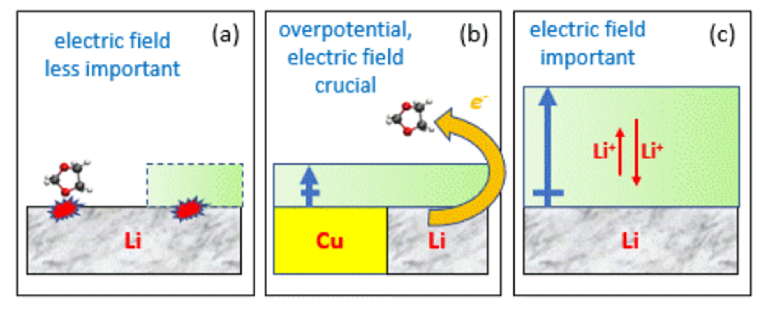
Next we consider the horizontal LiCu slabs. The “galvanic corrosion” concept is arguably most relevant in field deployment environments (e.g., on shipsjced ) where the overall metal voltage () is not controlled. In such conditions, we expect that creating a junction of two metals with different electronegativities raises above that of the more electronegative metal alone, at least prior to any induced electrochemical reaction that has occurred and has led to changes in .kelly This is indeed the situation for the oxide 1 model, where the three phase junction between Li2O, Li, and the more electropositive Cu raises the voltage from the =0.05 V value at the pure Li2O/Li interface (Fig. 2) to 0.85 V at the mixed interface (Fig. 3b). Li dissolution, and pitting through the oxide, would be accelerated at this higher . This scenario would be consistent with standard galvanic corrosion.jced Note that Li+ dissolution requires an acceptor. In the next section we show that DOL reduction is unfavorable at =0.85 V for this model; however, other electrolyte components, e.g., the anion, exhibit higher reduction potentials and can accept . This model bears similarities with Al corrosion. metal ion transport in the Al2O3 passivating film is slow prior to pitting.corrosion The onset potential for pitting depends on pH and salt concentration but is generally at values much higher than the standard Al plating voltage.pittingvoltage A large overpotential vs. metal-stripping is readily attainable in table-top electrochemical settings. At this onset, the passivating oxide is ruptured and Al3+ can readily dissolve.
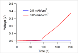
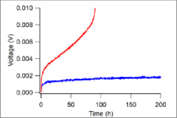
However, we argue that Fig. 3e is less relevant than Fig. 3f in batteries. Li+ diffuses much more readily in the SEI passivating film than Al3+ in its oxide without the need of first rupturing the SEI film. The lowering of kinetic constraint means that the anode should be near its equilibrium potential. Indeed, our measurements show that the Li-stripping occurs without significant over-voltage (0 V) (Fig. 3g-h), quantitatively similar to “oxide 2,” and is not at 0.85 V. This should be true in recent battery experiments as well.galvanic1 ; galvanic2 ; merrill
In that sense, oxide 1 (Fig. 4b) is a hypothetical, standard “galvanic corrosion” scenario that assumes that Li+ motion in the SEI is as slow as Al3+ in alumina. Oxide 2, where 0 V at room temperature, is more relevant to battery experiments (Fig. 3g-h). Even in this case, the DFT-predicted work function and local electrostatic potential remain lower on the Li side of the LiCu metal junction (Fig. 3f). The expected transfer of from the Li side to the Cu side due to their difference in electronegativity reduces the difference in arising from the pure Li and Cu metal work function difference, but does not eliminate or reverse it. For a CuAl metal junction, finite element simulations have also predicted local voltage increase on the more electropositive Cu side.haque This is qualitatively simillar to Fig. 3d-f, although the variation is much smaller, likely because an electric current exists in the model of Ref. haque, , and ohmic effects cannot be neglected. A more direct connection between metal corrosion (“oxide 1”), and SEI at a substantial potential (0.85 V), may however be made using passive anodes without Li content.maureen
SEI forms preferentially at lower voltages and metal dissolution into cations (e.g., via pitting) preferentially occurs at higher voltages. In the oxide 2 model (Fig. 4c), the variation in Fig. 3f suggests that, if the SEI thickness are the same on both Cu and Li sides, the Li side is at a 0.0 V potential. This suggests that the partially plated Li-regions in recent experimental workgalvanic1 ; galvanic2 ; merrill suppress Li dissolution via destruction of the passivating film (pitting-like corrosion), while electrolyte electrochemical reduction is enhanced. The Li-plated region is preferentially the cathode (electrochemically reducing electrolyte). “Pitting” does not occur in the Li-plated region; instead Li+ dissolution may occur at the LiCu junction or on the Cu-side where the final SEI is thinner. This would be a “cathodic” reaction driven corrosion – at least at the thin SEI thickness in our model – which is fundamentally different from standard anodic-limited local Al or steel corrosion initiation mechanisms; it may be more similar to Mg corrosion in water where the passivating film is less stable and hydrogen reduction reaction occurs more readily.mgwater This appears to contradict the proposed mechanism (Fig. 4 schematic) in Ref. galvanic1, . However, the Ref. galvanic1, analyses are performed after the SEI is fully formed, at which point the Li-side SEI is thicker than that on the Cu-side (unlike in our models) and SEI formation is more kinetically limited. Our argument concerning does not need to be altered to make this connection to the experimental work. SEI formation reactions will be explicitly examined in the next sections.
Thus we caution against a too-literal identification of traditional corrosion/galvanic corrosion concept in aqueous electrolytes with Li self-discharge. Future local voltage measurements in Li-plated and non-plated Cu current collectors, e.g., by using scanning Kelvin probe force microscopy, will be valuable to confirm this point.
Note that the experimental voltage (Fig. 3g-h) is slightly but measurably higher for a sample where Li has been plated on Cu at a very low capacity than when plated at higher capcity, especially at longer times. See the S.I. (Sec. S2) for details. The 0.01 V difference at early times cannot be resolved in current DFT calculations. At the lower Li capacity, we expect the large Cu surface area relative to the amount of plated Li to lead to rampant self-discharge. This suggests that when significant self-discharge occurs, the open circuit voltage is higher than the Li stripping potential of 0.0 V, which accelerates Li+ dissolution. This is in qualitative agreement with the oxide 1 model, although we stress that “oxide 1” is not meant to be physical, and the experimentally measured voltage is not as high as the 0.85 V. The difference in magnitude may be due to many factors, such as the effective time-scale difference, S.I., allowing change of Li configuration from oxide 1 to oxide 2.
III.4 CuLi Junction: Electrochemical Reduction of Solvent
Local electrostatic potential variation should be screened by low dielectric organic SEI far from electrode surfaces, but reduction reactions occurring right at the inoroganic SEI surface should be affected by the variation in (Fig. 3d-f). We next demonstrate the consequences of heterogeneity, and of overpotential, on interfacial stability. We compute DOL reductive decomposition energetics on “oxide 2” (Fig. 3c) surfaces where the overall is at the Li-plating voltage. Fig. 4a-b depict a decomposed DOL on the Li and the Cu sides of the oxide 2 model, at the peak and valley of the profile (Fig. 3f), respectively. Two-electron DOL decomposition is more favorable by =-1.15 eV on the Li-side versus -0.65 eV on the Cu-side in the largest supercells examined (Table 1). The difference between the two sides is 0.50 eV, reasonably close in magnitude than 2 times the 0.16 eV variation in (Fig. 3f); the latter is meant as a qualitative guide for explicit transfer reactions.
In contrast, the oxide 1 model exhibits a significantly higher overall (=0.85 V), which should impede DOL reductive decomposition that leads to SEI-formation. Indeed, =+0.31 eV and +0.87 eV on the Li- and Cu-sides, respectively in the largest cells considered (Table 1). The discrepancy between the Li and Cu sides on the oxide 1 model is qualitatively consistent with the larger variation (Fig. 3e), but again does not quantitatively describes the difference.
The reaction barriers for the forward reaction are irrelevant on “oxide 1” surfaces because the reactions are endothermic at the =0.85 V voltage there, and DOL decomposition should not occur. However, the reverse reaction, namely reconstitution of intact DOL molecules, is energetically downhill, and the reverse are lower than 1.0 eV (Table 1). This implies reaction time scales of at most 1 hour when using standard kinetic prefactors in Arrhenius rate estimates at T=300 K. for DOL decomposition in the largest simulation cell used is 0.80 eV (Table 1), which indicates that the reaction is fast relative to battery cycling (1-hour) time scales. At the transition state, the C-O bond being broken has a length of 2.11 Å in the oxide 2 model but is a much smaller 1.98 Å in the oxide 1 model, suggesting that differences exist between DOL decomposition mechanisms at different . At =-0.16 V, is significantly more negative than in “oxide 2,” and is even lower (S.I. Sec. S10); the DOL decomposition energetics may be non-linearly dependent on .
are not strongly dependent on the size of the vacuum region, unlike (Fig. 3). Increasing the cell size from =40 Å used in Fig. 4 to =50 Å on the Cu side of the oxide 1 model changes by at most 0.06 eV; the variations of between the Li- and Cu-sides are converged to within a few meV’s.
These predictions associated with Fig. 3b-c should definitively dispel the much-quoted misconception that voltages in DFT simulation cells are solely determined by , which are the Li insertion costs relative to Li metal cohesive energy.voltage_prb Li metal is present in both oxide 1 and oxide 2, but the associated with DOL decompositon due to cross-SEI-film transfer, which is a prototype voltage-dependent SEI formation reaction, varies significantly. even depends on the side of the simulation cell in which the reaction occurs. An equally incorrect corollary assumption is that the DFT simulation cell is always at electrochemical equilibrium (==0.0 V vs. Li+/Li(s)) if lithium metal exists in the cell. While is the correct equilibrium definition, it does not account for the possibility of instantaneous overpotential in DFT, or experimental, settings (S.I. Sec. S5). Unless is controlled by tuning the interfacial structure, it is very easy have accidental DFT overpotential that lead to qualitatively wrong conclusions (e.g., by incorrectly assuming that “oxide 1” represents a system is at -equilibrium and that DOL does not decompose on Li anode surfaces at -equilibrium, Fig. 4a,c). This emphasizes the point that all DFT modeling work on battery interfaces should calculate and report . When long-range transfer-induced SEI formation reaction occurs, the Li metal is not in contact with the species being electrochemically reduced; the surface-film coated electrode in effect acts like a passive electrode at short times (S.I. Sec. S5) just like in supercapacitors, and the electronic voltage used in supercapacitors and related disciplines is the correct definition. It is only by considering that the predictions in Fig. 4 can be rationalized.
| system | side | size | ||||
| Li/Li2O | NA | 11 | -0.85 eV | +0.83 eV | 0.09 V | 2.08 V |
| Li/Li2O | NA | 21 | -1.55 eV | +0.72 eV | 0.12 V | 0.89 V |
| Li/Li2O | NA | 22 | -1.72 eV | +0.67 eV | 0.01 V | 0.14 V |
| Li+Cu/Li2O | Lia | 11 | +0.67 eV | 0.75 eV | 0.77 V | 1.25 V |
| Li+Cu/Li2O | Lia | 12 | +0.40 eV | 0.91 eV | 0.83 V | 0.78 V |
| Li+Cu/Li2O | Lia | 13 | +0.21 eV | NA | 0.79 V | 0.54 V |
| Li+Cu/Li2O | Lia | 14 | +0.31 eV | NA | 0.79 V | 0.42 V |
| Li+Cu/Li2O | Cua | 11 | +1.26 eV | NA | 0.75 V | 0.99 V |
| Li+Cu/Li2O | Cua | 12 | +1.02 eV | NA | 0.82 V | 0.59 V |
| Li+Cu/Li2O | Cua | 13 | +0.87 eV | NA | 0.78 V | 0.43 V |
| Li+Cu/Li2O | Lib | 11 | -0.25 eV | 0.97 | -.04 V | 1.60 V |
| Li+Cu/Li2O | Lib | 12 | -1.09 eV | 0.80 | -.05 V | 0.95 V |
| Li+Cu/Li2O | Lib | 13 | -1.09 eV | NA | -.00 V | 0.65 V |
| Li+Cu/Li2O | Lib | 14 | -1.15 eV | NA | -.03 V | 0.48 V |
| Li+Cu/Li2O | Cub | 11 | +0.14 eV | 1.12 | -.04 V | 1.46 V |
| Li+Cu/Li2O | Cub | 12 | -0.53 eV | NA | -.05 V | 0.90 V |
| Li+Cu/Li2O | Cub | 13 | -0.65 eV | NA | -.00 V | 0.63 V |
| LiH | NA | 11 | -1.17 eV | +2.13 eV | NA | NA |
| Li/LiH | NA | 11 | -0.74 eV | +1.04 eV | 0.63 V | 1.10 V |
| Li/LiH | NA | -0.99 eV | +0.98 eV | +0.65 V | 0.56 V | |
| Li/LiH | NA | 22 | -0.89 eV | 0.93 eV | 0.67 V | 0.28 V |
III.5 Interpretations of Solvent Reduction at CuLi Junction
Our calculations suggest that the main “galvanic” effect of the LiCu junction is to enhance SEI formation on Li-plated regions over Cu regions. This is a cathodic reaction-driven process, distinct from traditional Al/steel pitting corrosion.
We stress that SEI films are thin (10 Å) in our models, and are not yet completely passivating, unlike in experiments where the inorganic SEI on the Li-side is completed and is reported not increase in thickness during subsequent Li dissolution in cryo-TEM measurements, at least for some cycles.galvanic1 In our models, more favorable DOL decomposition enthalpy (’s) are predicted on the Li side of CuLi junctions in both oxide 1 and oxide 2 at the same Li2O thickness. This enhanced tendency on Li, when the Li2O thickness is the same on both sides, is consistent with the thicker (15 nm) SEI ultimately formed on Li compared to that on Cu (5-8 nm).galvanic1 Measurement of SEI thickness on the Cu side as Li self-discharge proceeds would be valuable in future studies. Although we have focused on initial DOL decomposition reactions and have not explored ultimate SEI products, the different values of and predicted on the Li and Cu sides may be consistent with the different SEI compositions in the two types of regions.galvanic1 Indeed, the SEI formation potential has been reported to affect SEI composition and properties on other substrates.evolve3 See the S.I. (Sec. S1) for further XPS SEI analysis.
As discussed above, the “oxide 1” model is at significant overpotential (0.85 V) vs. Li-stripping. Such high voltages may be observed only after all active Li has been removed from the anode (Fig. 3g-h). The reverse reaction barriers () calculated for that model are likely underestimated because other decomposed DOL fragments and other Li+ cations, not included in the model, may bind to and stabilized the isolated, electrochemically reduced DOL in the equivalent of Fig. 4a-b for oxide 1 (without interlayer Li). However, our calculations raise the possibility SEI evolution at voltages higher than Li-stripping may involve reversal of SEI formation reactions. Note also that there are differences in the electrolytes used in this work and in Refs. galvanic1, ; galvanic2, ; merrill, .
III.6 LiH and DOL Reactions: Chemical vs. Electrochemical Self-discharge
LiH has recently reported to be an SEI component,lih1 ; lih2 although this finding has been disputed.lih3 Next we consider LiH in the SEI. H- is in its lowest possible charge state and, like other inorganic SEI components Li2O and LiF, LiH should be thermodynamically stable against Li metal. But unlike those components, LiH is a strong reducing agent that should react chemically with organic SEI and electrolyte components, even in the absence of an source. Thus, apart from the inherent interest in LiH within the SEI, this material serves as a model system to differentiate chemical versus electrochemical reactions with the electrolyte during SEI evolution, late-stage SEI growth, or self-discharge.
(a) 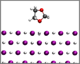
 (b)
(b)
(c) (d) (e)
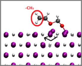
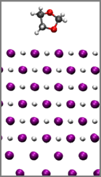
Fig. 5a-b depict intact and decomposed DOL configurations on the LiH (001) surface. These simulation cells omit metallic electrodes which are sources, and only chemical reactions are possible. In panel (b), a H2C-O bond is broken, and one of the H- on the LiH surface is now covalently bonded to the exposed CH2 group. =-1.17 eV (Table 1), indicating that the LiH surface reacts exothermically with DOL. An even more exothermic configuration, with =-2.63 eV, can be found if the H- surface “hole” is filled by another H- from the LiH (marked by an arrow in Fig. 5b). We expect that other organic molecules react exothermically with LiH as well.
However, SEI formation typically occurs at room temperature and the reactions are governed by kinetics, not just thermodynamics. Going from panel (a) to (b), the kinetic barrier =+2.13 eV is unexpectedly large, and the reaction cannot occur at T=300 K within battery operation time scales. As this simulation cell lacks a metal anode we do not report . No long-range charge transfer occurs here, and system size effects are expected to be small.
Next we add lithium metal to the backside of the LiH slab. The LiH (001)/Li (001) interface exhibits =+0.63 V without an adsorbed, intact DOL. This is significantly higher than the Li-plating potential. It indicates that the Li2O (111)/Li (001) and LiF (001)/Li (001) interfaces, which both exhibit 0.0 V without the need to create surface charges, are not universal features of Li/SEI interfaces. It also emphasizes that extra effort is needed to keep DFT model systems at -equilibrium, non-overpotential conditions.
Fig. 5c-d depict an intact and electrochemically decomposed DOL on the (001) surface of LiH-coated lithium metal, respectively. is 0.67 V for the intact DOL structure (Fig. 5a), similar to the 0.63 V computed without the DOL. The decomposed DOL has the same structure as that on Li2O (111) (Fig. 2b, Fig. 4b)). A C-O bond is broken, but there is no H- transfer from LiH to the DOL, unlike Fig. 5b. and are -1.32 eV and +1.04 eV for this reaction, respectively, in the largest cell considered. Since this system is at an overpotential vs. Li+/Li(s), DOL electrochemical reduction at Li-plating potential (0.0 V vs. Li+/Li(s)) should be even more favorable. In contrast, Fig. 5e depicts a reaction route which involves transfer of a H- to the DOL just like Fig. 5b. =-1.24 eV, very similar to the -1.17 eV without Li metal (Fig. 5b). is 0.67 V for the decomposed DOL, similar to that for Fig. 5c. The lack of a change in in a finite sized cell suggests that no is transferred, little change in dipole moment has occurred from the Li metal, and therefore the reaction is chemical, not electrochemical, in nature. As expected, the presence of the Li metal does not strongly affect purely chemical reactions. We have not computed but it is likely to be similar to the system without Li metal (Fig. 5a-b), and makes the reaction kinetically unfavorable.
For calculations on LiH film on Li metal slabs, the convergence with system size is significantly faster than on Li2O films (Fig. 4c-d). The reason may be the smaller LiH band gap, which translates into a larger dielectric constant; furthermore, the conduction band edge is much closer to than Li2O-coated Li metal (S.I. Sec. S3), which also increases the polarizability of the entire system. We have not considered additional mechanistic steps, like Li+ dissolving from the Li metal and coordinating to the DOL molecule, partly because the Fig. 5d configuration is already sufficiently favorable in terms of both energetics and kinetics; if adding more mechanistic complexity further lowers or , it would not change our conclusion.
These results indicate that in general, intermediate stage SEI growth, which consumes the electrolyte, can occur via both electrochemical and chemical routes. For LiH, the chemical route has high reaction barriers while the electrochemical route does not. If LiH is present in electrically disconnected regions of the SEI, it may have significant kinetic stability against the organic solvent and organic SEI components, and may exhibit a significant lifetime. Furthermore, if LiH is continously generated by electrolyte reaction with Li metal, the subsequent reaction of LiH with the electrolyte also leads to a net consumption of Li, and therefore self-discharge.
III.7 Li+ Vacancy at Li/LiAlO2 Interface: Electric Field Effects
In this section we survey two other aSEI/Li interfaces examples, namely, LiAlO2 and LiI, where are not naturally at 0.0 V vs. Li+/Li(s), discuss how to shift towards the Li-plating potential, and examine the potential consequences to battery operations. We also focus on the relative energy landscape related to Li+ vacancy diffusion and show that Li+ diffusion towards/away from the interface can become asymmetric. We do not focus on the absolute Li+ vacancy formation energies; at a given temperature there will be a certain population of such vacancies. Our explicit interface models used herein go beyond traditional semiconductor modelsfreysoldt and permit the treatment of thin SEI films, surface charges, electric fields, and contact potentials.
Alumina can be coated on Cu current collectors, or directly on Li surfaces, to create aSEIs.elam ; kozen ; merrill Upon cycling, it has been proposed that alumina reacts to form mixed Al/Li oxides.elam ; kozen ; lialox We focus on the mixed oxide candidate LiAlO2.jacs LiAlO2 is not thermodynamically stable against Li metal; its Al3+ can be reduced. However, we find that its (100) surface is kinetically stable on Li(001) upon optimization of the interfacial configuration (Fig. 6a), even after a short AIMD run (Method). In contrast, LiI,lii like LiH, has a maximally reduced anion which cannot react with Li metal (Fig. 6b).
(a) 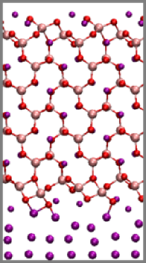 (b)
(b) 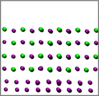
The electronic voltages associated with the two interfaces in Fig. 6a-b are +0.63 V and 1.29 V, respectively (Eq. 2). These interfaces are above the equilibrium (0.0 V vs. Li+/Li(s)) conditions. If a liquid electrolyte were present, Li metal would start to dissolve as Li+ until -equilibrium is achieved via surface charging. These values further confirm that the LiF- and Li2O-coated Li metal near-“open circuit” conditions are fortuitous exceptions. Despite this, the computed associated with LiAlO2/Li(s) and LiI/Li(s) interfaces remain significantly lower than the DFT/PBE predicted bare lithium “voltage” of 1.56 Vgb ; pccp due to the finite contact potentials. Once again, we emphasize that extra effort is needed to keep DFT model systems at -equilibrium, non-overpotential conditions. Charge-neutral Li2CO3-coated Li surfaces have been predicted to exhibit 0.6 V;filhol however, Li2CO3 is in fact not stable on Li surfaces.batt ; umd
The local densities of state (LDOS) plots in the S.I. (Sec. S3) illustrate the interfacial band structures. By construction, the interfaces are not charged, and as expected, in the insulating SEI/aSEI regions, the valence band edges (VBE) are flat. We have also performed spot-checks of the LiI with the more accurate HSE06 functional. The latter increases by 0.10 V compared to PBE predicitons (S.I. Sec. S3); this would also be the magnitude of the change in contact potential.
To illustrate the effect of contact potentials which do not give =0.0 V, we consider Li+ diffusion at the Li/LiAlO2 interface. First, we attempt to attain a voltage closer to 0.0 V vs. Li+/Li(s) than 0.63 V. This requires a positively charged surface which induces a negative charge on the Li metal surfaces, and creates a surface dipole (Eq. 3) and an electric field across the LiAlO2 film. The field inside LiAlO2 is the sole contribution to the EDL in our model. Changing the EDL by increasing the cation surface concentration is also the way voltage is lowered in modeling pristine electrodes/liquid electrolyte interfaces.borodin In Fig. 7c, we artificially substitute one or two O atoms with fluorine (F) near the LiAlO2/vacuum interface in 12 or 14 supercells respectively. This reduces from 0.63 V to 0.31 V, much closer to equilibrium Li-plating/stripping conditions. The LDOS (Fig. 7a) shows that the F atom(s) at the surface already creates a field, reflected in the slope of the VBE as increases (arrow in Fig. 7a). It also indicates a small amount of occupied surface states introduced by the F-atoms. Adding even more F atoms does not further lower below 0.31 V because is pinned by these surface impurity states. A more realistic model, with organic SEI and liquid electrolytes, appears necessary to lower further.
Fig. 7d depicts Li+-vacancy displacement energetics of this model. Five 14 and 24 simulation cells with one VLi+ each at different vertical positions are considered (Fig. 7c). The Li+ vacancy energy cost () decreases with distance from the inner surface (except the vacancy closest to the Li metal surface, which is an outlier). The S.I. (Sec. S7) shows that, without F-substitution such that =0.63 V, the reverse trend is observed; Li+ vacancy costs increase with increasing distance from the metal surface. This trend suggests that, for this Li/LiAlO2 interface, as the voltage further decreases towards -equilibrium (=0.0 V), should decrease with distance from the Li/LiAlO2 interace even faster than Fig. 7d. In other words, Li+ stripping from the Li metal anode through this film should exhibit a more favorable energy landscape than Li-plating, as long as only Li+ vacancies in LiAlO2, and not positively charged Li-interstitials, are involved. Such an asymmetry has seldom been documented at battery interface because finite electric fields are difficult to measure and have been largely neglected in DFT calculations. However, it may contribute to deviation of Li plating/stripping exchange current ratio from unity.butler We have not computed Li+ diffusion barriers, but those should also be affected by an electric field. A field that hinders Li+ vacancy diffusion towards the liquid elecrolyte in the SEI should reduce self-discharge. This would require a large, positive contact potential between Li metal and the surface film, so that at =0.0 V the Li/film interface is positively charged. Thus electric fields may be exploited to accelerate charging/discharge rate.
Surprisingly, are well-converged with system size (Fig. 7)d. This is unlike the case without F-substitution on the LiAlO2 surface (S.I.), or with Li2O films Fig. 4. Normally this lack of system size dependence would be the signature of an uncharged point defect.corrosion However, the LDOS (Fig. 7b) shows that a vacancy generates new VBE states, which are signatures of a negatively charged defect. We postulate that the partially occupied surface states are responsible for fast convergence (Fig. 7a-b). While the good system size convergence is computationally convenient, the existence of surface states is not physical; they should readily react with organic species if any were present on the surface. Creating an electric field via alternatives to F-substitution will be explored in future work.
IV Conclusions
We have examined a Li2O-coated, 50% Li-coverage Li/Cu metal junctions as models of Li metal partially plated on a Cu current collector in batteries with lithium metal anodes. Using DFT methods and these models with explicit interfaces, we show that these LiCu junctions exhibit significant spatial inhomogeneity with respect to local electrostatic potentials. DOL electrochemical reduction reactions are more favorable and faster on the Li side of oxide-coated junction. This suggests that solid electrolyte interphase (SEI) films form more readily on the Li region than the Cu region, if the SEI film has the same thickness on both regions. This is in qualitative agreement with the experimental finding that the final SEI on is thicker Li-coated regions under lithiun metal anode “galvanic corrosion” conditions. A 100% Li-coated Cu surface does not exhibit such an inhomogeneity or galvanic corrosion signatures.
We also show that LiH, a recently proposed component of SEI formed from liquid electrolyte decomposition, can react either chemically or electrochemically with organic solvent molecules. The electrochemical degradation process has a reasonably low reaction barrier consistent with about one second reaction time scales. The chemical route, while exothermic, has a surprisingly high barrier. This suggests that LiH may persist in electronically disconnected regions of the SEI despite its thermodynamic instability. If LiH is continuously formed in the SEI, it may continuously react electrochemically and deplete Li metal, which becomes relevant to battery self-discharge. Finally, we demonstrate that LiAlO2, a model for artificial SEI (aSEI) on Li metal, should exhibit a cross-film electric field when held at the plating/stripping potential (0.0 V vs. Li+/Li(s)). The field direction implies that the plating/stripping rates are intrinsically asymmetric. This feature can potentially be exploited to limit self-discharge batteries.
Our predictions are made possible by previous conceptual advances in DFT modeling of battery interfaces. These include voltage definitions (ionic/equilibrium, vs. electronic/instantaneous, ), DFT overpotential concepts (), accounting for contact potentials between lithium metal and the inorganic SEI/aSEI, and including an electric field across the surface film to constrain the system at a particular . , proportional to the Fermi level, is shown to be the key determinant of electrochemical reaction energetics when long-range transfer is involved; the ionic, equilibrium voltage , related to Li-insertion energies, is only indirectly relevant. Calculating is also critical for avoiding unintentional overpotential in DFT calculations that may lead to erroneous comparison with measurements.
We find that different artificial SEI or SEI components (Li2O, LiAlO2, LiI, and LiH) exhibit significantly different contact potentials. This means that, at the same applied voltage and film thickness, they would exhibit electric fields with different magnitudes across the films. From this and from our previous work,pccp ; gb ; lipon we postulate that electric fields have weak influence on chemical reactions between Li metal and the SEI/aSEI which are directly in contact; are more important for Li+ transport in the surface film and may therefore affect the stripping/plating rate ratio when using Butler-Volmer equations;butler and are crucial in determining the in-film voltage drop that governs long range leakage through the SEI/aSEI, which leads to late-stage SEI growth/evolution (Fig. 8). Electric fields inside the SEI are seldom discussed in the battery literature,maier and the contact potential is an even more obscure topic. Understanding how such fields (and the accompanying potential drops/rises) are partitioned among the surface films, the liquid electrolyte, and the contact potentials is an urgent need that requires further research.
In general, battery interfacial stability, related to cycling as well as self-discharge, is found to be far more complex than purely thermodynamic/phase diagram approaches, or standard galvanic corrosion models for metal corrosion, have postulated. While our conclusions are based on somewhat idealized models, we stress that for SEI formation reactions via long-range electron transfer, the voltage is critical. Indeed we focus on voltage-function relations rather than interface structure-function relations because the atomic details of interfaces have seldom been imaged. There are fundamental differences between Li metal self-discharge and corrosion/galvanic corrosion of metals like steel or aluminum, due to differences in voltage dependence and cation diffusion rate in oxides. Onset of pitting through breaching of the passivating film at elevated voltages relative to Li-plating is not required in Li self-discharge, unlike in pitting corrosion of Al or steel; indeed high potential impedes the cathodic reactions that lead to Li self-discharge. The different corrosion mechanisms mean different mitigating strategies should be applied. Nevertheless, we propose that synergistic study of battery interfaces and metal corrosion will yield significant cross-cutting benefits.
Acknowledgement
We thank Quinn Campbell for valuable suggestions. This work is funded by the Laboratory Directed Research and Development Program at Sandia National Laboratories. Sandia National Laboratories is a multi-mission laboratory managed and operated by National Technology and Engineering Solutions of Sandia, LLC, a wholly owned subsidiary of Honeywell International, Inc., for the U.S. Department of Energy’s National Nuclear Security Administration under contract DE-NA0003525. This paper describes objective technical results and analysis. Any subjective views or opinions that might be expressed in the document do not necessarily represent the views of the U.S. Department of Energy or the United States Government.
Supporting Information
The Supporting Information is available free of charge at https://pubs.acs.org/.
Experimental evidence for Li2O; experimental galvanic corrosion data; predicted local densities of state; DOL decomposition in solution and on Li surface; comparison with other battery interface DFT work; discussion of voltage definitions; Li+ vacancy diffusion without surface F-dopant; simulation cell details; DOL decomposition on Li2O surface; additional predictions on an“oxide 3” model; and surface/interfacial contributions to voltage
References
- (1) Xu, W.; Wang, J.L.; Ding, F.; Chen, X.L.; Nasybutin, E.; Zhang, Y.H.; Zhang, J.-G. Lithium Metal Anodes for Rechargeable Batteries, Energy Envir. Sci. 2014, 7, 513-537.
- (2) Lee, S.-Y.; Shangguan, J.Y.; Alvarado, J.; Betzler, S.; Harris, S.J.; Doeff, M.M.; Zheng, H. Unveiling the Mechanisms of Lithium Dendrite Suppression by Cationic Polymer Film Induced Solid-Electrolyte Interphase Modification Energy Envir. Sci. 2020, 13, 1832-1842.
- (3) Redondo-Iglesias, E.; Venet, P.; Pelissier, S.; Global Model for Self-Discharge and Capacity Fade in Lithium-Ion Batteries Based on the Generalized Eyring Relationship. IEEE Trans. Vehicular Tech. 2018, 67, 104-113.
- (4) Wood, S.M., Fang, C.C.; Dufek, E.J.; Nagpure, S.C.; Sazhin, S.V.; Liaw. B.; Meng, Y.S. Predicting Calendar Aging in Lithium Metal Secondary Batteries: The Impacts of Solid Electrolyte Interphase Composition and Stability. Adv. Energy Mater. 2018, 8, 1801427.
- (5) Boyle, D.T.; Huang, W.; Wang, H.S.; Li, Y.Z.; Chen, H.; Yu, Z.; Zhang, W.B.; Bao, Z.N.; Cui, Y. Corrosion of Lithium Metal Anodes During Calender Aging and its Microscopic Origins. Nat. Energy 2021 6, 487-494.
- (6) Lin, D.; Liu, Y.; Li, Y.; Li, Y.; Pei, A.; Xie, J.; Huang W.; Cui, Y.; Fast Galvanic Lithium Corrosion Involving a Kirkendall-type Mechanism. Nat. Chem. 2019, 11, 382-389.
- (7) Kolesnikov, A.; Kolek, M.; Dohmann, J.F.; Horsthemke, F.; Borner, M.; Bieker, P.; Winter M.; Stan, M.C. Galvanic Corrosion of Lithium-Powder-Based Electrodes Adv. Energy Mater. 2020, 10, 2000017.
- (8) Merrill, L.C.; Rosenberg, S.G.; Jungjohann, K.L.; Harrison, K.L. Uncovering the Relationship Between Aging and Cycling on Lithium Metal Battery Self-Discharge. ACS Appl. Energy Mater. 2021, 4, 7589-7598.
- (9) Dohmann, J.F.; Horsthemke, F.; Küpers, V.; Bloch, S.; Preibisch, Y.; Kolesnikov, A.; Kolek, M.; Stan, M.C.; Winter, M.; Bieker, P. Galvanic Couples in Ionic Liquid-Based Electrolyte Systems for Lithium Metal Batteries—An Overlooked Cause of Galvanic Corrosion? Adv. Energy Mater. 2021, 11, 2101021.
- (10) R.W. Revie (eds) Uhlig’s Corrosion Handbook, Third Edition. (Wiley, 2011)
- (11) Leung, K. DFT Modelling of Explicit Solid–Solid Interfaces in Batteries: Methods and Challenges. Phys. Chem. Chem. Phys. 2020, 22, 10412-10425.
- (12) He, X.; Bresser, D.; Passerini, S.; Baakes, F.; Krewer, U.; Lopez, J.; Mallia, C.T.; Shao-Horn, Y.; Cekic-Laskovic, I.; Wiemers-Meyer, S.; Soto, F.A.; Ponce, V.; Seminario, J.M.; Balbuena, P.B.; Jia, H.; Xu, W.; Xu, Y.B.; Wang, C.M.; Horstmann, B.; Amine, R.; Su, C.C.; Shi, J.Y.; Amine, K.; Winter, M.; Latz, A.; Kostecki, R. The Passivity of Lithium Electrodes in Liquid Electrolytes for Secondary Batteries. Nat. Mater. Rev. DOI10.1038/s41578-021-00345-5
- (13) Sanders, R.W.; Crettol, G.L.; Brown, J.D.; Plummer, P.T.; Schendorf, T.M.; Oliphant, A.; Swithenbank, S.B.; Ferrante R.F.; Gray, J.P. Teaching Electrochemistry in the General Chemistry Laboratory through Corrosion Exercises. J. Chem. Educ. 2018, 95, 824-846.
- (14) Qi, Y.; Ban C.M.; Harris, S.J. New General Paradigm for Understanding and Preventing Li Metal Penetration through Solid Electrolytes. Joule 2020, 4, 2599-2608.
- (15) Ma, T.Y.; Xu, G.-L.; Li, Y.; Wang, L.; He, X.M.; Zheng, J.M.; Liu, J.; Engelhard, M.H.; Zapol, P.; Curtiss, L.A.; Jorne, J.; Amine, K.; Chen, Z.H. Revisiting the Corrosion of the Aluminum Current Collector in Lithium-Ion Batteries J. Phys. Chem. Lett. 2017, 8, 1073-1077.
- (16) Xu, K. Electrolytes and Interphases in Li-Ion Batteries and Beyond. Chem. Rev., 2014, 114, 11503-11618.
- (17) Schechter, A.; Aurbach, D.; Cohen, H. X-ray Photoelectron Spectroscopy Study of Surface Films Formed on Li Electrodes Freshly Prepared in Alkyl Carbonate Solutions. Langmuir 1999, 15, 3334-3342.
- (18) See Wang, A.P.; Kadam, S.; Li, H.; Shi, S.Q.; Qi, Y. Review on Modeling of the Anode Solid Electrolyte Interphase (SEI) for Lithium-Ion Batteries. NPJ Computational Materials, 2018, 4, 15, for a comprehensive review.
- (19) Diddens, D.; Appiah, W.A.; Mabrouk, Y.; Heuer, A.; Vegge, T.; Bhowmik, A. Modeling the Solid Electrolyte Interphase: Machine Learning as a Game Changer? Adv. Mater. Interfaces 2022, 2101734
- (20) Butler, K.T.; Gautam, G.S.; Canepa, P. Designing Interfaces in Energy Materials Applications with First Principles Calculations. NPJ Comput. Mater. 2019, 5, 19.
- (21) Kozen, A.C.; Lin, C.-F.; Pearse, A.J.; Schroeder, M.A.; Han, X.; Hu, L.; Lee, S.-B.; Rubloff, G.W.; Noked, M. Next-Generation Lithium Metal Anode Engineering. ACS Nano 2015, 6, 5884-5892.
- (22) Chen, L.; Connell, J.G.; Nie, A.; Huang, Z.; Zavadil, K.R.; Klavetter, K.C.; Yuan, Y.; Sharifi-Asi, S.; Shahbazian-Yassar, R.; Libera, J.A.; Mane, A.U.; Elam, J.W. Lithium Metal Protected by Atomic Layer Deposition Metal Oxide for High Performance Anodes. J. Mater. Chem. A 2017, 5, 12297-12309.
- (23) Zhou, Z.Q.; Lu, P.; Delacourt, C.; Qiao, R.M.; Xu, K.; Pan, F.; Harris, S.J. Yang, W.L. Breathing and Oscillating Growth of Solid-Electrolyte-Interphase Upon Electrochemical Cycling. Chem. Commun., 2018, 54, 814-817.
- (24) Veith, G.M.; Doucet, M.; Baldwin, J.K.; Sacci, R.L.; Fears, T.M.; Wang, Y.Q.; Browning, J.F. Direct Determination of Solid-Electrolyte Interphase Thickness and Composition as a Function of State of Charge on a Silicon Anode. J. Phys. Chem. C, 2015, 119, 20339-20349.
- (25) Lu, P.; Li, C.; Schneider, E.W.; Harris, S.J. Chemistry, Impedance, and Morphology Evolution in Solid Electrolyte Interphase Films during Formation in Lithium Ion Batteries. J. Phys. Chem. C 2014, 118, 896-903.
- (26) Guo, R.; Wang, D.; Zuin, L.; Gallant, B.M. Reactivity and Evolution of Ionic Phases in the Lithium Solid-Electrolyte Interphase. ACS Energy Lett. 2021, 6, 877-885.
- (27) Guo, R.; Gallant, B.M. Li2O solid electrolyte interphase: probing transport properties at the chemical potential of lithium. Chem. Mater. 2020, 32, 5525-5533.
- (28) Santos, E.; Schmickler, W. The Crucial Role of Local Excess Charges in Dendrite Growth on Lithium Electrodes. Angew. Chem. Int. Ed. 2021, 60, 5876-5881.
- (29) Chen, S.R.; Zheng, J.M.; Mei, D.M.; Han, K.S.; Engelhard, M.H.; Zhao, W.G.; Xu, W.; Liu, J.; Zhang, J.-G. High-Voltage Lithium-Metal Batteries Enabled by Localized High-Concentration Electrolytes. Adv. Mater. 2018, 30, 1706102
- (30) Yamada, Y.; Usui, K.; Sodeyama, K.; Ko, S.; Tateyama, Y.; Yamada, A. Hydrate-Melt Electrolytes for High-Energy-Density Aqueous Batteries. Nat. Energy 2016, 1, 16129
- (31) Stenrück, H. G.; Cao, C.T.; Lukatskaya, M.R.; Takacs, C.J.; Wan, G.; Mackanic, D.G.; Tsao, Y.; Zhao, J.B.; Helms, B.A.; Xu, K.; Borodin, O.; Wilshart, J.F.; Toney, M.F. Interfacial Speciation Determines Interfacial Chemistry: X-ray-Induced Lithium Fluoride Formation from Water-in-salt Electrolytes on Solid Surfaces. Angew. Chem. Int. Ed. 2020, 59, 23180-23187.
- (32) Yildirim, H.; Haskins, J.B.; Bauschlicher, C.W.; Lawson, J.W. Decomposition of Ionic Liquids at Lithium Interfaces. 1. Ab Initio Molecular Dynamics Simulations. J. Phys. Chem. C, 2017, 121, 28214-28234.
- (33) Baskin, A.; Lawson, J.W.; Prendergast, D. Anion-Assisted Delivery of Multivalent Cations to Inert Electrodes. J. Phys. Chem. Lett., 2021, 12, 4347-4356.
- (34) Lin, Y.X.; Wen, Z.P.; Liu, J.X.; Wu, D.Z.; Zhang, P.; Zhao, J.H. Constructing a Uniform Lithium Iodide Layer for Stabilizing Lithium Metal Anode. J. Energy Chem. 2021, 55, 129-135.
- (35) Swift, M.W.; Qi, Y. First-principles Prediction of Potentials and Space-charge Layers in All-solid-state Batteries. Phys. Rev. Lett., 2019, 122, 167701.
- (36) Gerischer, H.; Decker, F,; Scrosati, B. The Electronic and the Ionic Contribution to the Free Energy of Alkali Metals in Intercalation Compounds. J. Electrochem. Soc. 1994, 141, 2297-2300.
- (37) Zachman, M.J.; Tu, Z.; Choudhury, S.; Archer, L.A.; Kourkoutis, L.F. Cryo-STEM Mapping of Solid–Liquid Interfaces and Dendrites in Lithium-Metal Batteries. Nature, 2018, 560, 345-351.
- (38) Shadike, Z.; Lee, H.; Borodin, O.; Cao, X.; Fan, X.L.; Wang, X.L.; Liu, R.Q.; Bak, S.-M.; Ghose, S. Xu, K.; Wang, C.S.; Liu, J.; Xiao, J.; Yang, X.-Q.; Hu, E.Y. Identification of LiH and Nanocrystalline LiF in the Solid-Electrolyte Interphase of Lithium Metal Anodes. Nature Nanotech. 2021, 16, 549-554.
- (39) Fang, C.C.; Li, J.X.; Zhang, M.H.; Zhang, Y.H.; Yang, F.; Lee, J.Z.; Lee, M.-H.; Alvarado, J.; Schroeder, M.A.; Yang, Y.Y.C.; Lu, B.Y.; Williams; N.; Ceja, M.; Yang, L.; Cai, M.; Gu, J.; Xu, K.; Wang, X.F.; Meng, Y.S. Quantifying Inactive Lithium in Lithium Metal Batteries. Nature, 2019, 572, 511-515.
- (40) Our solid-solid interface focus is not meant to suggest the liquid electrolytes do not play a critical role in battery stabiilty; high salt concentration electrolytes,highconc ; highconc2 ; wise anions effects,baskin and electrolyte additives which yield different aSEI components, like LiI,lii are examples of liquid electrolyte effects.
- (41) Haruyama, J.; Ikeshoji, T.; Otani, M. Electrode Potential from Density Functional Theory Calculations Combined with Implicit Solvation Theory. Phys. Rev. Mater. 2018, 2, 095801.
- (42) Kastlunger, G.; Lindgren, P.; Peterson, A.A. Controlled-Potential Simulation of Elementary Electrochemical Reactions: Proton Discharge on Metal Surfaces J. Phys. Chem. C, 2018, 122, 12771-12781.
- (43) Van den Bossche, M.; Skulason, E.; Rose-Petruck, C.; Jonsson, H.; Assessment of Constant-Potential Implicit Solvation Calculations of Electrochemical Energy Barriers for H-2 Evolution on Pt. J. Phys. Chem. C, 2019, 123, 4116-4124.
- (44) Deibenbeck, F.; Freysoldt, C.; Todorova, M.; Neugebauer, J.; Wippermann, S. Dielectric Properties of Nanoconfined Water: A Canonical Thermopotentiostat Approach. Phys. Rev. Lett. 2021, 126, 136803.
- (45) Campbell, Q.; Dabo, I. Quantum-Continuum Calculation of the Surface States and Electrical Response of Silicon in Solution. Phys. Rev. B, 2017, 95, 205308.
- (46) Hörmann, N.G.; Andreussi, O.; Marzari, N. Grand canonical Simulations of Electrochemical Interfaces in Implicit Solvation Models. J. Chem. Phys., 2019, 150, 041730.
- (47) Hagopian, A.; Doublet, M.-L.; Filhol, J.-S. Thermodyamic Origin of Dendrite Growth in Metal Anode Batteries. Energy Envir. Sci. 2020, 13, 5186.
- (48) Pham, T.A.; Kweon, K.E.; Samanta, A.; Ong, M.T.; Lordi, V.; Pask, J.E. Intercalation of Lithium into Graphite: Insights from First-Principles Simulations. J. Phys. Chem. C 2020, 124, 21985-21992.
- (49) Leung, K. First Principles, Explicit Interface Studies of Oxygen Vacancy and Chloride in Alumina Films for Corrosion Applications. J. Electrochem. Soc. 2021, 168, 031511.
- (50) Xiao, C.; Usiskin, R.; Maier, J. Passivation Layers in Lithium and Sodium Batteries: Potential Profiles, Stabilities, and Voltage Drops. Adv. Funct. Mater. 2021, 31, 2100938.
- (51) Leung, K.; Jungjohann, K.L. Spatial Heterogeneities and Onset of Passivation Breakdown at Lithium Anode Interfaces. J. Phys. Chem. C 2018, 121, 20188-20196.
- (52) Yu, X.-X.; Marks, L. Combining the Physics of Metal/Oxide Heterostructure, Interface Dipole, Band Bending, Crystallography, and Surface State to Understand Heterogeneity Contrast in Oxidation and Corrosion. Corrosion, 2019, 75, 152-166.
- (53) See, e.g., Fu, M.S.; Yao, Z.P.; Ma, X.; Dong, H.; Sun, K.; Hwang, S.; Hu, E.Y.; Gan, H.; Yao, Y.; Stach, E.A.; Wolverton, C.; Su, D. Expanded Lithiation of Titanium Disulfide: Reaction Kinetics of Multi-Step Conversion Reaction. Nano Energy, 2019, 63, 103882.
- (54) Nagy, K.S.; Kazemiabnavi, S.; Thornton, K.; Siegel, D.J. Thermodynamic Overpotentials and Nucleation Rates for Electrodeposition on Metal Anodes. ACS Appl. Mater. Interfaces 2019, 11, 7954-7964.
- (55) Yu, H.C.; Ling, C.; Bhattacharya, J.; Thomas, J.C.; Thornton, K.; Van der Ven, A. Designing the Next Generation High Capacity Battery Electrodes. Energy Environ. Sci. 2014, 7, 1760-1768.
- (56) Ceder, G.; Hautier, G.; Jain, A.; Ong, S.P. Recharging Lithium Battery Research with First-Principles Methods. MRS Bull., 2011, 36, 185-191.
- (57) Dawson, J.A.; Canepa, P.; Famprikis, T.; Masquelier, C.; Islam, M.S. Atomic-Scale Influence of Grain Boundaries on Li-Ion Conduction in Solid Electrolytes for All-Solid-State Batteries. J. Am. Chem. Soc. 2018, 140, 362-368.
- (58) Zhu, Y.Z.; He, X.F.; Mo, Y.F. Origin of Outstanding Stability in the Lithium Solid Electrolyte Materials: Insights from Thermodynamic Analyses Based on First- Principles Calculations. ACS Appl. Mater. Interface 2015, 7, 23685-23693.
- (59) Fielder, C.; Luerssen, B.; Rohnke, M.; Sann, J.; Janek, J. XPS and SIMS Analysis of Solid Electrolyte Interphases on Lithium Formed by Ether-Based Electrolytes. J. Electrochem. Soc. 2017, 164, A3742-3749.
- (60) Leung, K.; Qi, Y.; Zavadil, K.R.; Jung, Y.S.; Dillon, A.C.; Cavanagh, A.S.; Lee, S.H.; George, S.M. Using Atomic Layer Deposition to Hinder Solvent Decomposition in Lithium Ion Batteries: First-Principles Modeling and Experimental Studies. J. Am. Chem. Soc. 2011, 133, 14741.
- (61) Yada, C.; Ohmori, A.; Ide, K.; Yamasaki, H.; Kato, T.; Saito, T.; Sagane, F.; Iriyama. Dielectric Modification of 5V-class Cathodes for High-Voltage All-Solid-State Lithium Batteries. Adv. Energy Mater. 2014, 4, 1301416.
- (62) Ye, M.; Zhao, W.; Li, J.; Yang, Y.; Zhang, Y.; Zhang, G.; Li, C.C. Integration of Localized Electric-Field Redistribution and Interfacial Tin Nanocoating of Lithium. Appl. Mater. Interfaces 2021, 13, 650-659.
- (63) Kresse, G.; Furthmüller, J. Efficient Iterative Schemes for Ab Initio Total-Energy Calculations Using a Plane-wave Basis Set. Phys. Rev. B 1996, 54, 11169-11186.
- (64) Kresse, G.; Furthmüller, J. Efficiency of Ab-initio Total Energy Calculations for Metals and Semiconductors using a Plane-Wave Basis Set. Comput. Mater. Sci. 1996, 6, 15-50.
- (65) Kresse G.; Joubert, D. From Ultrasoft Pseudopotentials to the Projector Augmented-Wave Method. Phys. Rev. B 1999, 59, 1758-1775.
- (66) Paier, J.; Marsman, M.; Kresse, G. Why Does the B3LYP Hybrid Functional Fail for Metals? J. Chem. Phys. 2007, 127, 024103.
- (67) Perdew, J.P., Burke, K.; Ernzerhof, .M. Generalized Gradient Approximation Made Simple. Phys. Rev. Lett. 1996, 77, 3865-3868.
- (68) Heyd, J.; Scuseria, G.E.; Ernzerhof, M. Hybrid Functionals based on a Screened Coulomb Potential. J. Chem. Phys. 2003, 118, 8207-8215.
- (69) Heyd, J.; Scuseria, G.E.; Ernzerhof, M. Hybrid Functionals Based on a Screened Coulomb Potential. J. Chem. Phys. 2006, 124, 219906.
- (70) Vydrov, O.A.; Heyd, J.; Krukau, A.V.; Scuseria, G.E. Importance of Short-Range versus Long-Range Hartree Fock Exchange for the Performance of Hybrid Density Functionals. J. Chem. Phys., 2006, 125, 074106.
- (71) Neugebauer, J.; Scheffler, M. Adsorbate-Substrate and Adsorbate-Adsorbate Interactions of Na and K adlayers on Al(111). Phys. Rev. B 1992, 46, 16067-16080.
- (72) Henkelman, G.; Uberuaga, B.P.; Jonsson, H. A Climbing Image Nudged Elastic Band Method for Finding Saddle Points and Minimum Energy Paths. J. Chem. Phys. 2000, 113, 9901-9985.
- (73) Schechter, A.; Aurbach, D.; Cohen, H. X-ray Photoelectron Spectroscopy Study of Surface Films Formed on Li Electrodes Freshly Prepared in Alkyl Carbonate Solutions. Langmuir, 1999, 15, 3334-3342.
- (74) Cheng, X.B.; Yan, C.; Zhang, X.-Q.; Lui, H. Zhang, Q. Electronic and Ionic Channels in Working Interfaces of Lithium Metal Anodes. ACS Energy Lett. 2018, 3, 1564-1570.
- (75) Nishikawa, K.; Shinoda, K. Characterization of Electrodeposited Li Metal by Cryo-Scanning Transmission Electron Microscopy/Electron Energy Loss Spectroscopy. J. Phys. Chem. Lett. 2021, 12, 3022=3027.
- (76) Han, B.; Li, X.: Bai, S.; Zou, Y.; Lu, B.; Zhang, M.; Ma, X.; Chang, Z.; Meng, Y.S.; Gu, M. Conformal Three-Dimensional Interphase of Li Metal Anode Revealed by Low Dose Cryo-Electron Microscopy. https://arxiv.org/abs/2106.08754
- (77) Li, Y.; Li, Y.; Pei, A.; Yan, K.; Sun, Y.; Wu, C.-L.; Joubert, L.-M.; Chin, R.; Koh, A.L.; Yu, Y.; Perrino, J.; Butz, B.; Chu, S.; Cui, Y. Atomic Structure of Sensitive Battery Materials and Interfaces Revealed by Cryo–Electron Microscopy. Science 2017, 358, 506-510.
- (78) Jungjohann, K.L.; Gannan, R.N.; Goriparti, S.; Randolph, S.J.; Merrill, L.C.; Johnson, D.C.; Zavadil, K.E.; Harris, S.J.; Harrison, K.L. Cryogenic Laser Ablation Reveals Short-Circuit Mechanism in Lithium Metal Batteries. ACS Energy Lett. 2021, 6, 2138-2144.
- (79) Leung, K.; Soto, F.; Hankins, K.; Balbuena, P.B.; Harrison, K.L. Stability of Solid Electrolyte Interphase Components on Lithium Metal and Reactive Anode Material Surfaces. J. Phys. Chem. C 2016, 120, 6302-6313.
- (80) Han, B.; Zhang, Z.; Zou, Y.; Xu, K.; Xu, G.; Wang, H.; Meng, H.; Deng, Y.H.; Li, J.; Gu, M. Poor Stability of Li2CO3 in the Solid Electrolyte Interphase of a Lithium-Metal Anode Revealed by Cryo-Electron Microscopy. Adv. Mater. 2021, 33, 2100404.
- (81) Aydinol, M.K.; Kohan, A.F.; Ceder, G.; Cho, K.; Joannopoulos, J. Ab initio Study of Lithium Intercalation in Metal Oxides and Metal Dichalcogenides. Phys. Rev. B, 1997, 56, 1354-1365.
- (82) S. Trasatti. The Absolute Electrode Potential: An Explanatory Note. J. Electroanal. Chem. 1986, 209, 417-428.
- (83) Our previous non-equilibrium Green’s Function (NEGF/DFT) work suggests that ballistic transport through an 1 nm thick LiF film without defect is only 10 times slower than a LiF film of the same thickness with a grain boundary.gb2 See Smeu, M.; Leung, K. Electron leakage through heterogeneous LiF on lithium–metal battery anodes. Phys. Chem. Chem. Phys. 2021, 23, 3214-3218l
- (84) Delp, S.A.; Borodin, O.; Olguin, M.; Eisner, C.G.; Allen, J.L.; Jow, T.R. Importance of Reduction and Oxidation Stability of High Voltage Electrolytes and Additives. Electrochim. Acta 2016, 209, 498-510.
- (85) Kazemiabnavi, S.; Dutta, P.; Banerjee, S. Density Functional Theory Based Study of the Electron Transfer Reaction at the Lithium Metal Anode in a Lithium-Air Battery with Ionic Liquid Electrolytes. J. Phys. Chem. C 2014, 118, 27183-27192.
- (86) Kim, J.; Savoie, B.M.; Miller, T.F. Interfacial Electron Transfer and Ion Solvation in the Solid Electrolyte Interphase. J. Phys. Chem. C 2021, 125, 4614-4622.
- (87) Warburton, R.E.; Yong, M.J.; Letourneau, S.; Elam, J.W., Greeley, J. Descriptor-Based Analysis of Atomic Layer Deposition Mechanisms on Spinel LiMn2O4 Lithium-Ion Battery Cathodes. Chem. Mater. 2020, 32, 1794-1806.
- (88) See, e.g., Fig. 6 in: Borodin, O.; Ren, X.; Vatamanu, J.; Cresce, A.v.W.; Knap, J.; Xu., K. Modeling Insight into Battery Electrolyte Electrochemical Stability and Interfacial Structure. Acc. Chem. Res., 2017, 50, 2886-2894.
- (89) Braun, S.; Yada, C.; Latz, A. Thermodynamically Consistent Model for Space-Charge-Layer Formation in a Solid Electrolyte. J. Phys. Chem. C 2015, 119, 22181-22288.
- (90) Okuno, Y.; Ushirogata, K.; Sodeyama, K.; Shukri, G.; Tateyama, Y. Structures, Electronic States, and Reactions at Interfaces between LiNi0.5Mn1.5O4 Cathode and Ethylene Carbonate Electrolyte: A First-Principles Study. J. Phys. Chem. C, 2019, 123, 2267-2277.
- (91) Gao, B.; Jalem, R.; Ma, Y.; Tateyama, Y. Li+ Transport Mechanism at the Heterogeneous Cathode/Solid Electrolyte Interface in an All-Solid-State Battery via the First-Principles Structure Prediction Scheme. Chem. Mater. 2020, it, 85-96.
- (92) Nakamura, T.; Amezawa, K.; Kulisch, J.; Zeier, W.G.; Janek, J. Guidelines for All-Solid-State Battery Design and Electrode Buffer Layers Based on Chemical Potential Profile Calculation. ACS Appl. Mater. Interfaces 2019, 11, 19968-19976.
- (93) Chao, C.Y.; Lin, L.F.; Macdonald, D.D. A Point Defect Model for Anodic Passive Films I. Film Growth Kinetics. J. Electrochem. Soc. 1981, 128, 1187-1194.
- (94) Lautar, A.K.; Bitenc, J.; Rejec, T.; Dominko, R.; Filhol, J.-S.; Doublet, M.-L. Electrolyte Reactivity in the Double Layer in Mg Batteries: An Interface Potential-Dependent DFT Study. J. Am. Chem. Soc., 2020, 142, 5146-5153.
- (95) Longo, R.C.; Camacho-Forero, L.E.; Balbuena, P.B. Charge-Mediated Cation Deposition on Metallic Surfaces. J. Mater. Chem. A 2019, 7, 8527-8539.
- (96) Madsen, K.E.; Bassett, K.L., Ta, K., Sforzo, B.A.; Matusik, K.E.; Kastengren, A.L.; Gewirth, A.A. Direct Observation of Interfacial Mechanical Failure in Thiophosphate Solid Electrolytes with Operando X-Ray Tomography. Adv. Mater. Interfaces 2020, 7, 2000751.
- (97) Aizawa, Y.; Yamamoto, K.; Sato, T.; Murata, H.; Yoshida, R.; Fisher, G.A.J.; Kato, T.; Iriyama, Y.; Hirayama, T. In situ Electron Holography of Electric Potentials Inside a Solid-State Electrolyte: Effect of Electric Field Leakage. Ultramicroscopy, 2017, 178, 20-26.
- (98) Stegmaier, S.; Voss, J.; Reuter, K.; Luntz, A. Li+ Defects in a Solid-State Li Ion Battery: Theoretical Insights with a Li3OCl Electrolyte. Chem. Mater. 2017, 29, 4330-4340.
- (99) Liang, J.Y., Zeng, X.X., Zhang, X.D.; Wang, P.F.; Ma, J.Y.; Yin, Y.X.; Wu, X.W.; Guo, Y.G.; Wan, L.J. Mitigating Interfacial Potential Drop of Cathode-Solid Electrolyte via Ionic Conductor Layer To Enhance Interface Dynamics for Solid Batteries. J. Am. Chem. Soc. 2018, 140, 6767-6770.
- (100) Li, Y.; Leung, K.; Qi, Y. Connecting the irreversible capacity loss in Li-ion batteries with the electronic insulating properties of solid electrolyte interphase (SEI) components. Acc. Chem. Res. 2016, 49, 2363.
- (101) Zhang, P.; Zhu, J.J.; Wang, M.; Imanishi, N.; Yamamoto, O. Lithium dendrite suppression and cycling efficiency of lithium anode. Electrochem. Comun. 2018, 87, 27-30.
- (102) Han, J.; Zheng, Y.; Guo, N.; Balbuena, P.B., Calculated Reduction Potentials of Electrolyte Species in Lithium-Sulfur Batteries. J. Phys. Chem. C 2020, 124, 20654-20670.
- (103) Liu, Q.; Cresce, A.; Schroeder, M.; Xu, k.; Mu, D.; Wu, B.; Shu, L.; Wu, F. Insight on lithium metal anode interphasial chemistry: Reduction mechanism of cyclic ether solvent and SEI film formation. Energy Storage Mater. 2019, 17, 366-373.
- (104) Henkelman, G.; Arnaldsson, A.; Jónsson, H. A Fast and Robust Algorithm for Bader Decomposition of Charge Density. Comput. Mater. Sci. 2006, 36, 354-360.
- (105) Haque, Z.; Clark, B.A.; Lillard, R.S. Experimental Considerations for Modeling Galvanic Corrosion in Aluminum and its Alloys. Corrosion, 2018, 74, 903-913.
- (106) Kabra, V.; Parmananda, M.; Fear, C.; Usseglio-Viretta, F.L.E.; Colclasure, A.; Smith, K.;Mukherjee, P.P. Mechanistic Analysis of Microstructural Attributes to Lithium Plating in Fast Charging. ACS Appl. Mater. Interfaces 2020, 12, 55795-55808.
- (107) Liu, C.; Kelly, R.G. The Use of Finite Element Methods (FEM) in the Modeling of Localized Corrosion. Electrochem. Soc. Interface 2014, Winter, 47-51.
- (108) Jung, S.C.; Han, Y.-K. How Do Li Atoms Pass through the Al2O3 Coating Layer during Lithiation in Li-ion Batteries? J. Phys. Chem. Lett. 2013, 4, 2681-2685. We do not use the stoichiometry in this DFT work because it is metallic and cannot truly be an aSEI.
- (109) Bessone, J.B.; Salinas, D.R.; Mayer, C.E.; Ebert, M.E.; Lorenz, W.J. An EIS Study of Aluminum Barrier-Type Oxide Films Formed in Different Media. Electrochim. Acta 1992, 37, 2283-2290.
- (110) Li, T.; Perea, D.E.; Schreiber, D.K.; Wirth, M.G.; Orren, D.J.; Frankel, G.S. Cryo-based structural characterization and growth model of salt film on metal. Corr. Sci. 2020, 174, 108812.
- (111) Leung, K.; Pearse, A.J.; Talin, A.A.; Fuller, E.J.; Rubloff, G.W.; Modine, N.A. Kinetics-Controlled Degradation Reactions at Crystalline LiPON/LixCoO2 and Crystalline LiPON/Li-Metal Interfaces. ChemSusChem 2018, 11, 1956-1969.
- (112) Tang, M.; Newman, J. Why is the Solid-Electrolyte-Interphase Selective? Through-Film Ferrocenium Reduction on Highly Oriented Pyrolytic Graphite. J. Electrochem. Soc. 2012, 159, A1922-A1927.
- (113) Esmailya, m.; Svensson, J.E.; Fajardo, S.; Birbilis, N.; Frankel, G.S.; Virtanen, S.; Arrabal, R.; Thomas, S.; Johansson, L.G. Fundamentals and Advances in Magnesium Alloy Corrosion. Prog. Mater. Sci. 2017, 89, 92-193.
- (114) Berliner, M.D.; McGill, B.C.; Majeed, M.; Hallinan, D.T. Electrochemical Kinetics of Lithium Plating and Stripping in Solid Polymer Electrolytes: Pulsed Voltammetry. J. Electrochem. Soc. 2019, 166, A297-A304.
- (115) Freysoldt, C.; Grabowski, B.; Hickel, T.; Neugebauer, J.; Kresse, G. First-principles Calculations for Point Defects in Solids. Rev. Mod. Phys. 2014, 86, 253-305.