Optomechanical vibration of a nanofilm arising from luminescence-induced optical force
Abstract
Optical force, which is generated by the exchange of momentum between light and matter, has been applied in a wide range of fields including molecular biology, photochemistry, and optomechanics as a technique to manipulate small objects for atomic and micro-sized regimes. So far, the main approach for various optical manipulations has been the geometric design of the irradiated light, such as optical vortices and localized surface plasmons. On the other hand, luminescence from materials should also act as optical force, which we call luminescence-induced optical force (LiOF). LiOF occurs by designing an anisotropic dielectric environment surrounding an isotropic emitter. In this paper, as a model, we assumed a Fabry-Perot cavity structure in which a luminescent nanofilm is placed parallel to a metallic mirror. Then, we theoretically calculated the LiOF and revealed that the LiOF could drive the vibrational motion of the film. This mechanism will provide new insights into developing unconventional optomechanics.
Optical force, which is generated by the exchange of momentum through the interaction of light and matter, has been used as a technology to control the motion of small objects in various fields such as molecular biology (Ashkin1986, ; Xin2014, ; Corsetti2021, ), photochemistry (Ito2011, ; Cheng2020, ), and optomechanics (Aspelmeyer2014, ). In recent years, it has become possible to control the kinetic motion of micro-materials by using a tightly focused laser beam. To efficiently trap and manipulate small material’s motion, one should realize an efficient scattering or absorption of light. Further, for flexible motion control, the geometrical design of the light field has been crucial. For example, optical vortices with orbital angular momentum (Allen1992, ; Tamura2019, ; Tao2021, ) and strongly localized field by localized surface plasmon resonance near the metal gaps (Tsuboi2010, ; Wang2011, ; Shoji2020, ) have been utilized.
On the other hand, when an emitter is irradiated with light, luminescence occurs due to the excitation of electrons in the emitter, which also generates optical force. If the dielectric environment surrounding the emitters is uniform, isotropic luminescence occurs from isotropic emitters. In this case, the luminescence does not contribute to the motion of the emitter itself. Actually, the optical force induced by luminescence has been poorly discussed thus far. However, if we design the dielectric structure surrounding the emitters so that the luminescence occurs anisotropically, the luminescence-induced optical force (LiOF) will act on the emitter itself, resulting in moving autonomously. From the above perspective, we theoretically propose an unconventional type of optical manipulation using luminescence from emitters.
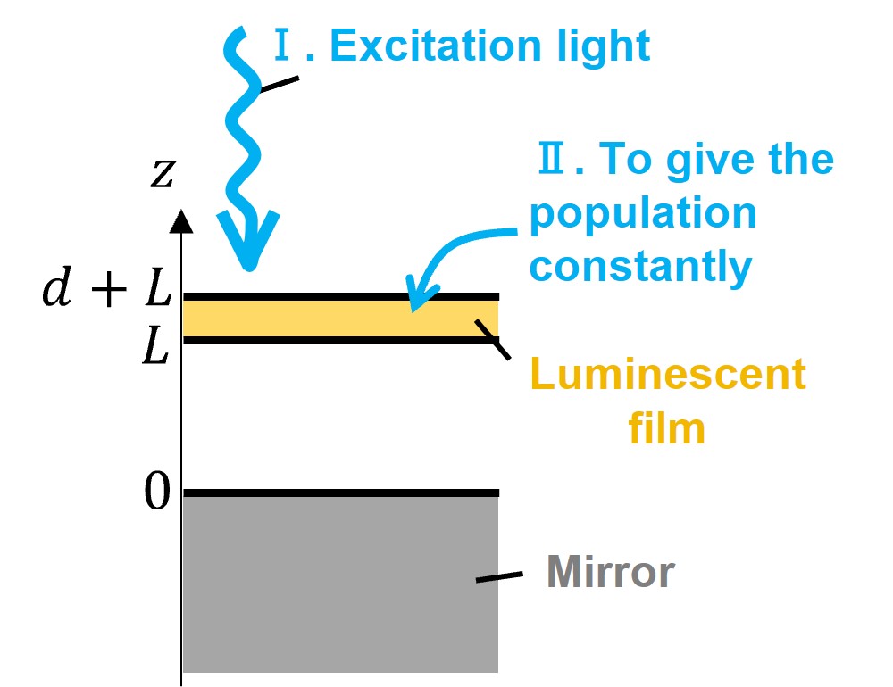
In this study, we considered a system in which a Fabry-Perot resonator structure formed between a luminescent nanofilm and a metallic mirror by placing the film parallel to the mirror (vacuum/film/vacuum/mirror), as shown in Fig. 1. In this case, the photoluminescence (PL) electric field is enhanced or suppressed in the cavity depending on the distance between the film and the mirror due to the optical confinement effect. The spatial anisotropy of the PL electric field at both surfaces of the film results in LiOF. We examined whether it was possible to induce the vibrational motion of the film by using the enhancement and suppression of the LiOF. In this study, in order to actively use luminescence to manipulate the motion of materials, we assumed organic-inorganic layered perovskites , which is a promising light-emitting materials. As the parameters of the emitter, the transverse energy and the longitudinal-transverse (LT) splitting energy of the exciton are given as eV, meV, respectively (IshiharaT1989, ). The background dielectric constant was set to 4.25 by the average of the dielectric constants of the organic and inorganic layers (IshiharaT1990, ; Hong1992, ).
In this study, we developed the LiOF theory, which referred to the PL theory of excitons in solids (Matsuda2016, ) and the optical force theory derived from Maxwell’s stress tensor (Iida2002, ). The Hamiltonian considers a coupled system of excitons and radiation fields as below.
| (1) | |||||
where represents the creation (annihilation) operator of the -th exciton state and represents the creation (annihilation) operator of the -th photon mode with the energy . is the excitonic polarization operator, and is the electric field operator. Since the center-of-mass motion of excitons are confined in the film’s thickness direction (-direction), the eigenenergies of the exciton are expressed as , where is the quantized wavenunber with . The excitons in the film are bound to inorganic () layers, so we treated the translational mass of the exciton as . We derived Heisenberg equations of exciton operator from the quantum master equation considering the non-radiative decay and the dephasing processes. Subsequently, we solved their equations with the quantum Maxwell equation, , expressed by Green’s function self-consistently (Cho, ), where Green’s function reflects the spatial structure (Chew, ). By performing Fourier transform, we obtained the expectation values of exciton operators under the steady-state conditions, and we calculated the PL spectrum , which we treated the incoherent component of electric field intensity as the PL intensity (Carmichael, ).
The time-averaged optical force exerted on the film per unit area can be expressed as follows, considering only the force acting perpendicular to the film’s surface (in -direction).
| (2) | |||||
where represents the electric field with upward (downward) wavenumber at the lower surface of the film shown in Fig. 1, and represents the electric field with upward (downward) wavenumber at the upper surface of the film. is vacuum permittivity and is the incident angle of excitation light.
To calculate the LiOF , we use the PL intensity obtained by the process described before. in Eq.(2) is the PL intensity at the upper surface of the film, and is zero. Besides, is obtained by solving the PL electric field at three arbitrary positions inside the cavity that are different from each other. The PL intensity inside the cavity () is described as, Finally, LiOF is obtained by integrating with the emission frequency. On the other hand, optical force by excitation light (coherent component of optical force) can also be quantitatively evaluated as .
The mechanical motion of the emitter is given by the following equation of motion,
| (3) |
where represents the optical force exerted on film. As parameters of the system, kHz is the mechanical frequency by a fixed luminescent film and nm is the film’s initial position. is the film’s mass per unit area, where we assumed the film with the density of 3 (Stoumpos2016, ) and the thickness of nm. The quality factor was given as , and the mechanical damping constant is obtained by . In this paper, we solved the simple equation (3), assuming that the size of the mechanical resonator was enough large relative to the vibrational amplitude, without considering the film’s deformation or nonlinear vibration.
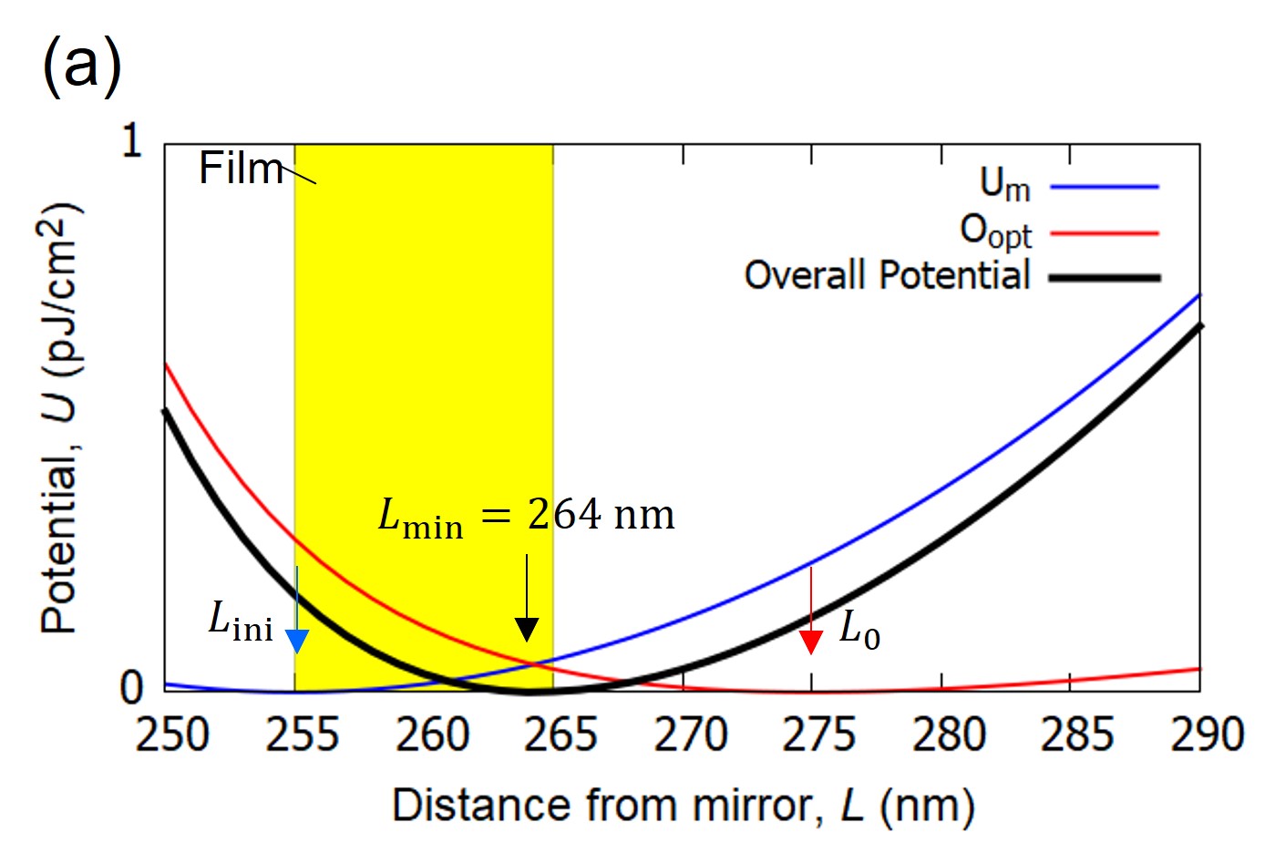
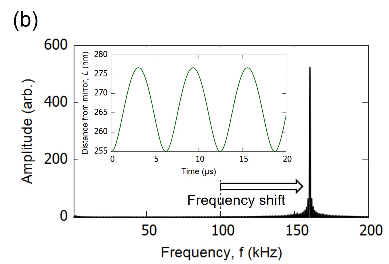
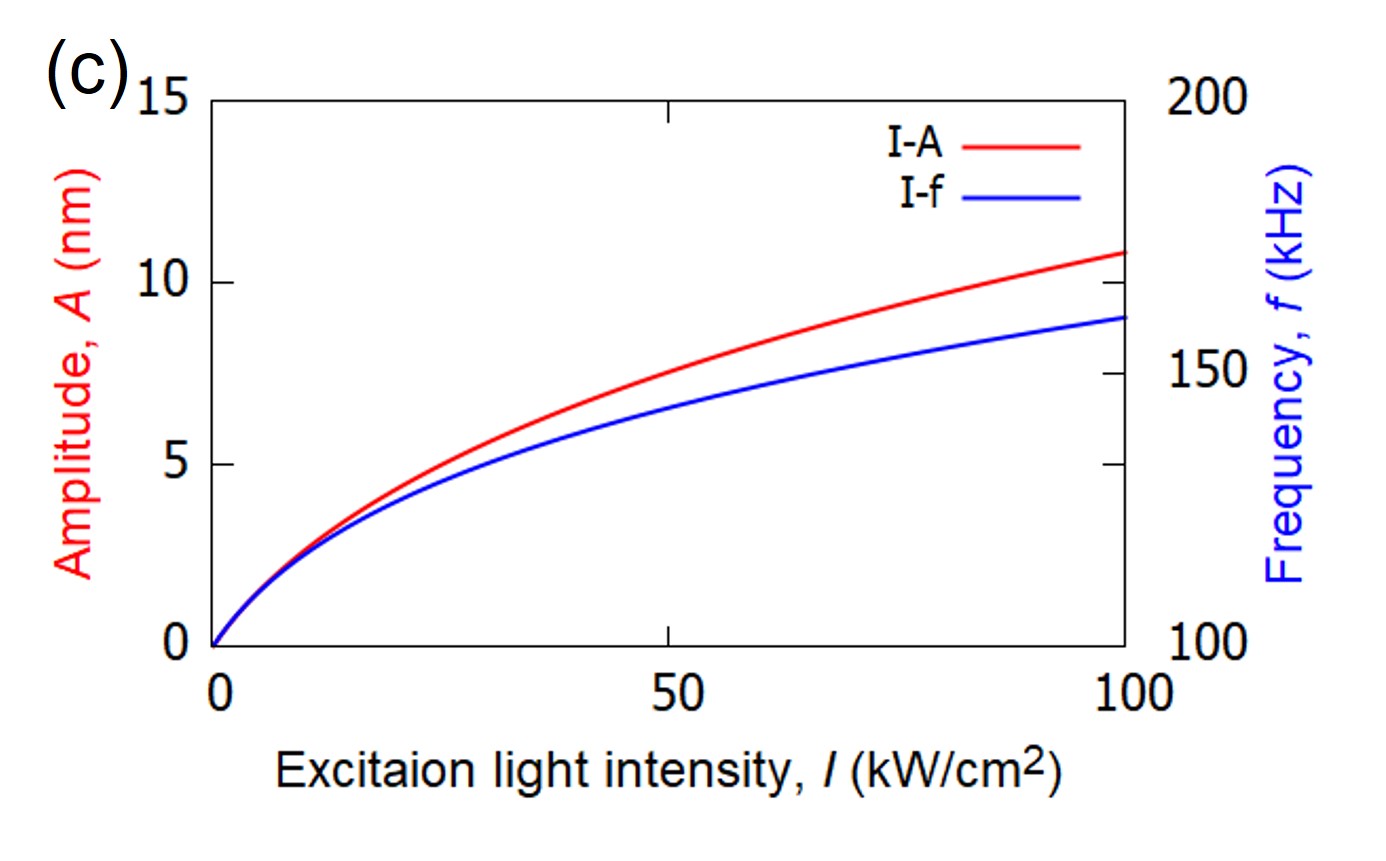
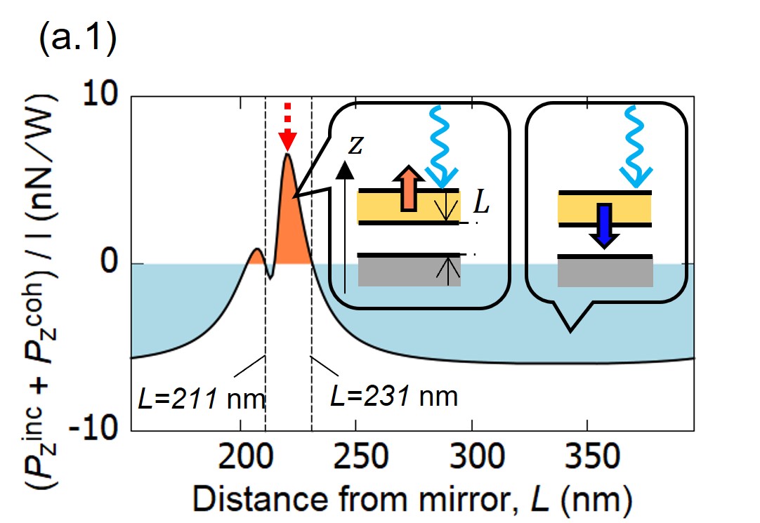
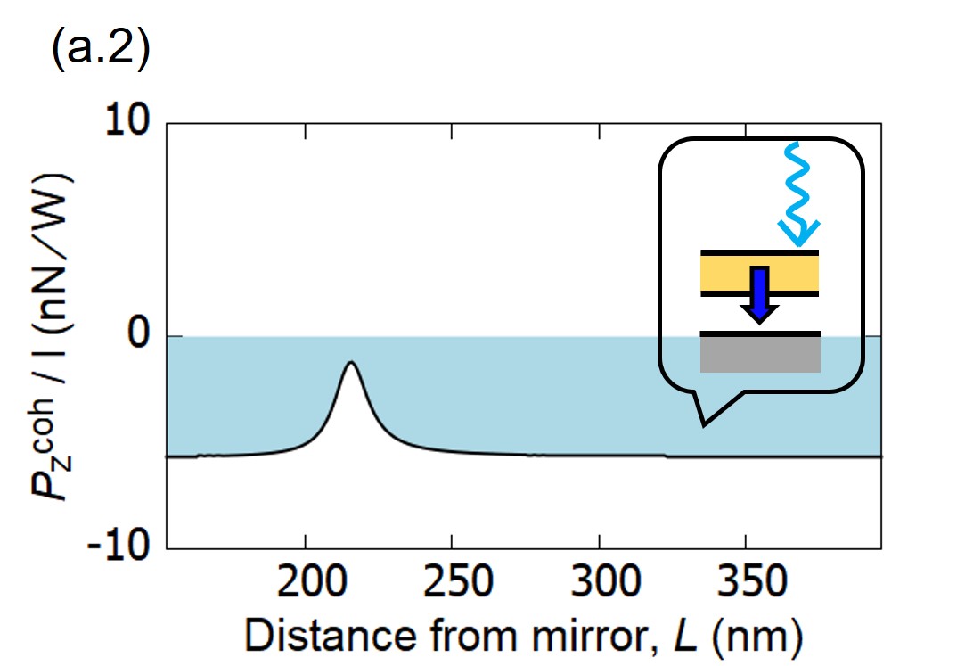
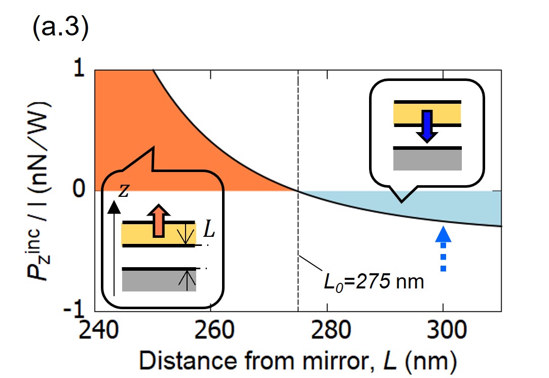
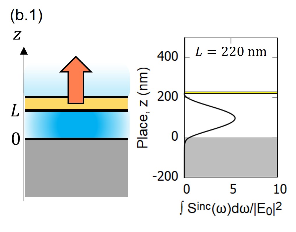
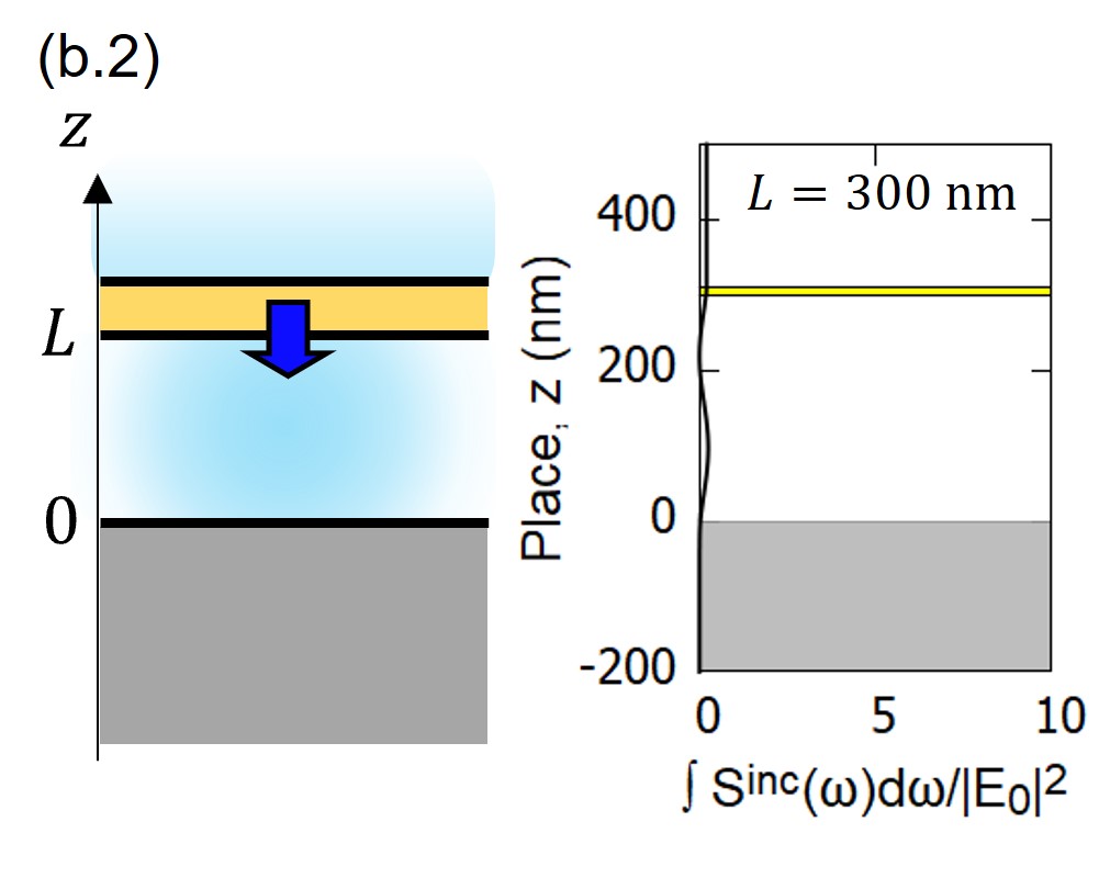
Fig. 2(a) shows the result of the optical force exerted on the luminescent film when the distance between the film and mirror is changed. Here, we assumed the luminescent film occurred the steady PL by irradiating the electronic resonant light ( eV) from the top of the film as shown in Fig. 1 (). In Fig. 2(a.1), the optical force is the sum of the LiOF and the optical force by excitation light , and the enhancement and suppression of the optical force repeat in a half-wavelength period ( 244 nm). To understand the mechanism of optical force enhancement, we separately evaluated the optical force by excitation light (a.2) and the LiOF (a.3). We find that repulsive force is not observed in Fig. 2(a.2) while the LiOF acts as repulsive force as shown in (a.3). Fig. 2(b) shows the spatial distribution of the PL electric intensity under the enhancement (b.1) and suppression (b.2) of the LiOF. As shown in Fig. 2(b.1), the optical enhancement shows photons are strongly confined inside the cavity. These results indicate the enhancement of the LiOF is due to the repeated multiple reflections of the strongly confined photons inside the cavity, which increases the repulsive force. In addition, there is a dip in the LiOF near the distance where the LiOF is most enhanced. It is because the film is located at the node of the standing wave of the excitation light, and it is not excited well. Then, there is almost no luminescence, and the LiOF is extremely small. As shown in Fig. 2(a.1), we find nm is the stable equilibrium position and the optical force acts as restoring force around there, suggesting that the film undergoes vibrational motion. However, when only the optical force by excitation light is considered like in Fig. 2(a.2), the optical force pushing the film becomes dominant regardless of the distance due to the electronic resonant condition, and there is no stable equilibrium position. In other words, luminescence enables us to induce vibrational motion of the film.
Even when only LiOF is considered (Fig. 2(a.3)), the stable equilibrium position exists at nm. It means that it is expected that vibrational motion can be induced even if only the LiOF is considered. Thus, in Fig. 3, we calculated the vibrational motion of the film induced by only the LiOF when the film is placed at initial position nm. As excitation method for the calculation of the LiOF in Fig. 3, we assumed the situation of supplying the film with the excitation energy equivalent to the irradiation of a resonant light with the intensity as shown in Fig. 1(). In the result of Fig. 3(a), the overall potential shifts from the mechanical potential to optical potential by the LiOF. The amplitude and frequency of the induced vibration obey the overall potential as shown in Fig. 3(b). The frequency shifts from the mechanical frequency ( kHz) due to the optical spring effect. By observing its shift, the contribution of optical force can be confirmed experimentally (Sheard2004, ). Fig. 3(c) shows the dependence of the maximum amplitude and the frequency of the luminescence-induced vibrational motion on the excitation intensity . On the rise of the excitation intensity, the amplitude and frequency increase by the LiOF. The results of Fig. 3(c) can be interpreted by approxmating the contribution due to the LiOF as a linear spring, , where is optical spring constant. The minimum of the overall potential is expressed as follows.
| (4) |
Here, the optical spring constant is , and also the amplitude is . Thus, in Fig. 3(c) can be drawn from Eq. (4). As for in Fig. 3(c), the spring constant of the overall potential is . The frequency is expressed as,
| (5) |
When the excitation intensity is further increased and the optical potential becomes dominant over the mechanical potential, the film vibrates at a frequency based on the optical potential.
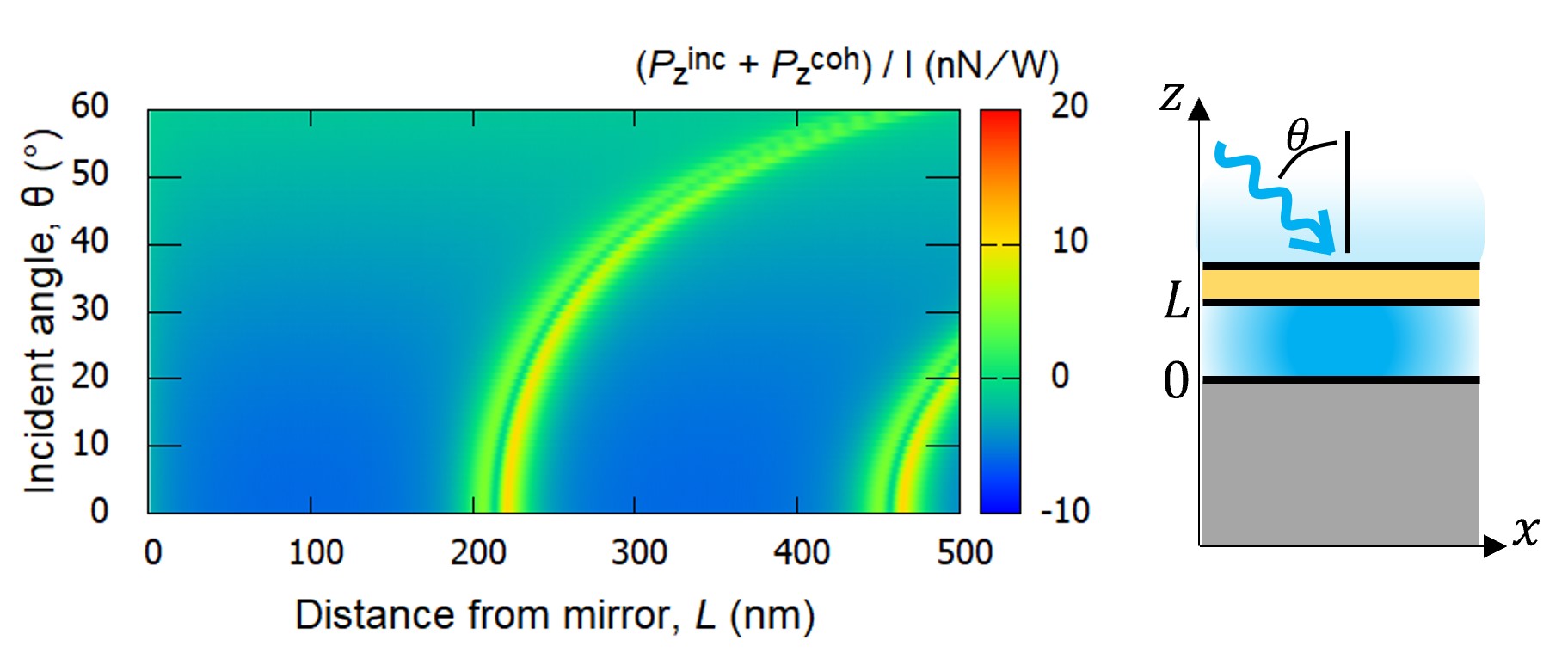
In Fig. 3, we fixed the film’s initial position nm. On the other hand, it is possible to drive the film’s vibration regardless of by changing the incident angle of the excitation light. Here, we considered the sum of the optical force including the contribution by excitation light like in Fig. 2(a.1). Fig. 4 shows the -dependence of the optical force exerted on the film when s-polarized excitation light was incident at an angle . The results show that the position enhancing the optical force shifts by changing the incident angle. The shift is due to the change in the vertical ( direction) wavenumber of the light. The component of the light wavenumber decreases by increasing the incident angle, which means that the wavelength of light propagating in the direction increases. So, increasing the incident angle corresponds to changing the PL wavelength of the film.
In summary, we have developed the luminescence-induced optical force (LiOF) theory by referencing the PL theory of excitons in solids and optical force theory and have proposed an unprecedented optical manipulation using LiOF. As a result, we have demonstrated that even if a luminescent film occurs isotropic luminescence, it is possible to induce vibrational motion of the film by the LiOF with realistic parameters by making the anisotropic dielectric environment surrounding the emitter, such as the Fabry-Perot cavity structure consisting of a luminescent film and a metallic mirror. Remarkably, it is also clear that LiOF plays an essential role to induce the vibrational motion of the film, and we can propose an optomechanical system under electronic resonance conditions driven by the LiOF. The present results are expected to open up a new research field based on manipulations by LiOF obtained through the design of the environment of the targeted systems, which is different from the conventional optical manipulations through designing the spatial structure of the irradiated light field. In addition, this research proposes not only new optical manipulations using luminescence but a mechanism that converts luminescence into mechanical motion reflecting the properties of the emitters. Therefore, its mechanism will propose a new scheme of fluorescence spectroscopy by observing the emitter’s mechanical motion. Also, by coupling the luminescence-induced optomechanical system in this paper with the other quantum systems such as superconductor qubits (Pirkkalainen2015, ; Cady2019, ) and magnon (Zhang2016, ; Li2018, ; Qi2021, ), it may be possible to have access to quantum properties of emitters, which leads to applications to quantum properties processing and quantum transducers. If we can control the fluctuation and deformation of the film by LiOF, it is expected to narrow the luminescence spectrum,which leads to develop a high-quality photon source (Ohta2021, ).
In recent years, many researchers have studied materials with high PLQY(Photoluminescence Quantum Yield) such as perovskites (Deschler2014, ; Bekenstein2015, ; Peng2016, ; Xie2020, ), which will help us to realize optical manipulation using luminescence in the future.
References
- (1) A. Ashkin, J. M. Dziedzic, J. E. Bjorkholm, and S. Chu, Observation of a Single-Beam Gradient Force Optical Trap for Dielectric Particles, Opt. Lett. 11, 288 (1986).
- (2) H. Xin, Q. Liu, and B. Li, Non-Contact Fiber-Optical Trapping of Motile Bacteria: Dynamics Observation and Energy Estimation, Sci. Rep. 4, 6576 (2014).
- (3) S. Corsetti and K. Dholakia, Optical Manipulation: Advances for Biophotonics in the 21st Century, J. Biomed. Opt. 26, (2021).
- (4) S. Ito, Y. Tanaka, H. Yoshikawa, Y. Ishibashi, H. Miyasaka, and H. Masuhara, Confinement of Photopolymerization and Solidification with Radiation Pressure, J. Am. Chem. Soc. 133, 14472 (2011).
- (5) A.-C. Cheng, H. Niinomi, T. Omatsu, S. Ishida, K. Sasaki, and T. Sugiyama, Plasmonic Manipulation-Controlled Chiral Crystallization of Sodium Chlorate, J. Phys. Chem. Lett. 11, 4422 (2020).
- (6) M. Aspelmeyer, T. J. Kippenberg, and F. Marquardt, Cavity Optomechanics, Rev. Mod. Phys. 86, 1391 (2014).
- (7) L. Allen, M. W. Beijersbergen, R. J. Spreeuw, and J. P. Woerdman, Orbital Angular Momentum of Light and the Transformation of Laguerre-Gaussian Laser Modes, Phys. Rev. A 45, 8185 (1992).
- (8) M. Tamura, T. Omatsu, S. Tokonami, and T. Iida, Interparticle-Interaction-Mediated Anomalous Acceleration of Nanoparticles under Light-Field with Coupled Orbital and Spin Angular Momentum, Nano Lett. 19, 4873 (2019).
- (9) Y. Tao, T. Yokoyama, and H. Ishihara, Rotation of Optically Bound Particle Assembly due to Scattering Induced Spin-Orbit Coupling of Light, http://arxiv.org/abs/2104.11387.
- (10) Y. Tsuboi, T. Shoji, N. Kitamura, M. Takase, K. Murakoshi, Y. Mizumoto, and H. Ishihara, Optical Trapping of Quantum Dots Based on Gap-Mode-Excitation of Localized Surface Plasmon, J. Phys. Chem. Lett. 1, 2327 (2010).
- (11) K. Wang, E. Schonbrun, P. Steinvurzel, and K. B. Crozier, Trapping and Rotating Nanoparticles Using a Plasmonic Nano-Tweezer with an Integrated Heat Sink, Nat. Commun. 2, 469 (2011).
- (12) T. Shoji, K. Itoh, J. Saitoh, N. Kitamura, T. Yoshii, K. Murakoshi, Y. Yamada, T. Yokoyama, H. Ishihara, and Y. Tsuboi, Plasmonic Manipulation of DNA Using a Combination of Optical and Thermophoretic Forces: Separation of Different-Sized DNA from Mixture Solution, Sci. Rep. 10, 3349 (2020).
- (13) T. Inoue, Y. Anno, Y. Imakita, K. Takei, T. Arie, and S. Akita, Resonance Control of a Graphene Drum Resonator in a Nonlinear Regime by a Standing Wave of Light, ACS Omega 2, 5792 (2017).
- (14) T. Ishihara, J. Takahashi, and T. Goto, Exciton State in Two-Dimensional Perovskite Semiconductor (C10H21NH3)2PbI4, Solid State Commun. 69, 933 (1989).
- (15) T. Ishihara, J. Takahashi, and T. Goto, Optical Properties due to Electronic Transitions in Two-Dimensional Semiconductors, Phys. Rev. B: Condens. Matter Mater. Phys. (1990).
- (16) X. Hong, T. Ishihara, and A. V. Nurmikko, Dielectric Confinement Effect on Excitons in PbI4-Based Layered Semiconductors, Phys. Rev. B Condens. Matter 45, 6961 (1992).
- (17) T. Matsuda, N. Yokoshi, and H. Ishihara, Upconverted Photoluminescence Induced by Radiative Coupling between Excitons, Phys. Rev. B: Condens. Matter Mater. Phys. 93, (2016).
- (18) T. Iida and H. Ishihara, Study of the Mechanical Interaction between an Electromagnetic Field and a Nanoscopic Thin Film near Electronic Resonance, Opt. Lett. 27, 754 (2002).
- (19) K. Cho,Optical Response of Nanostructures: MicroscopicNonlocal Theory, Springer Series in Solid-State Sciences(Springer-Verlag, Berlin, 2003).
- (20) W. C. Chew,Waves and Fields in Inhomogeneous Media (IEEE,New York, 1995).
- (21) H. J. Carmichael, Statistical Methods in Quantum Optics1: Master Equations and Fokker-Planck Equation (Springer,Berlin, 1998).
- (22) C. C. Stoumpos, D. H. Cao, D. J. Clark, J. Young, J. M. Rondinelli, J. I. Jang, J. T. Hupp, and M. G. Kanatzidis, Ruddlesden–Popper Hybrid Lead Iodide Perovskite 2D Homologous Semiconductors, Chem. Mater. 28, 2852 (2016).
- (23) B. S. Sheard, M. B. Gray, C. M. Mow-Lowry, D. E. McClelland, and S. E. Whitcomb, Observation and Characterization of an Optical Spring, Phys. Rev. A 69, 051801 (2004).
- (24) J.-M. Pirkkalainen, S. U. Cho, F. Massel, J. Tuorila, T. T. Heikkilä, P. J. Hakonen, and M. A. Sillanpää, Cavity Optomechanics Mediated by a Quantum Two-Level System, Nat. Commun. 6, 6981 (2015).
- (25) J. V. Cady, O. Michel, K. W. Lee, R. N. Patel, C. J. Sarabalis, A. H. Safavi-Naeini, and A. C. Bleszynski Jayich, Diamond Optomechanical Crystals with Embedded Nitrogen-Vacancy Centers, Quantum Sci. Technol. 4, 024009 (2019).
- (26) X. Zhang, C.-L. Zou, L. Jiang, and H. X. Tang, Cavity Magnomechanics, Science Advances 2, e1501286 (2016).
- (27) J. Li, S.-Y. Zhu, and G. S. Agarwal, Magnon-Photon-Phonon Entanglement in Cavity Magnomechanics, Phys. Rev. Lett. 121, 203601 (2018).
- (28) S.-F. Qi and J. Jing, Magnon-Assisted Photon-Phonon Conversion in the Presence of Structured Environments, Phys. Rev. A 103, 043704 (2021).
- (29) F. Deschler, M. Price, S. Pathak, L. E. Klintberg, D.-D. Jarausch, R. Higler, S. Hüttner, T. Leijtens, S. D. Stranks, H. J. Snaith, M. Atatüre, R. T. Phillips, and R. H. Friend, High Photoluminescence Efficiency and Optically Pumped Lasing in Solution-Processed Mixed Halide Perovskite Semiconductors, J. Phys. Chem. Lett. 5, 1421 (2014).
- (30) Y. Bekenstein, B. A. Koscher, S. W. Eaton, P. Yang, and A. P. Alivisatos, Highly Luminescent Colloidal Nanoplates of Perovskite Cesium Lead Halide and Their Oriented Assemblies, J. Am. Chem. Soc. 137, 16008 (2015).
- (31) L. Peng, A. Tang, C. Yang, and F. Teng, Size-Controlled Synthesis of Highly Luminescent Organometal Halide Perovskite Quantum Dots, J. Alloys Compd. 687, 506 (2016).
- (32) Z. Xie, X. Li, R. Li, S. Lu, W. Zheng, D. Tu, Y. Feng, and X. Chen, In Situ Confined Growth of Ultrasmall Perovskite Quantum Dots in Metal–organic Frameworks and Their Quantum Confinement Effect, Nanoscale 12, 17113 (2020).
- (33) R. Ohta, L. Herpin, V. M. Bastidas, T. Tawara, H. Yamaguchi, and H. Okamoto, Rare-Earth-Mediated Optomechanical System in the Reversed Dissipation Regime, Phys. Rev. Lett. 126, 047404 (2021).