Anomalous Faraday effect in a -symmetric dielectric slab
Abstract
In this letter we discuss a phase transition-like anomalous behavior of Faraday rotation angles in a simple parity-time () symmetric model with two complex -potential placed at both boundaries of a regular dielectric slab. In anomalous phase, the value of one of Faraday rotation angles turns negative, and both angles suffer spectral singularities and yield strong enhancement near singularities.
Introduction:
Faraday rotation (FR) is a magneto-optical phenomenon that rotates the polarization of light. It occurs either due to the internal property of the medium or to the external magnetic field applied. In both cases, the dielectric permittivity tensor of the system becomes anisotropic Landau and Lifshitz (1984). The Faraday effect shows a wide range of applications in various fields of modern physics, such as, (i) measuring magnetic field in astronomy Longair (2011); (ii) construction of optical isolators for fiber-optic telecommunication systems Furdyna (1988); or (iii) optical circulators that are used in the design of microwave integrated circuits Berger (2003); Turner and Stolen (1981); Firby et al. (2018). Usually it is necessary either a large size or a strong external magnetic field in order to obtain a large FR in bulk magneto-optical materials. Garbusi and Ferrari (2003); Richard et al. (2000). However, for small size systems, where the de Broglie wavelength is compatible with size of systems, a large enhancement of the FR and as well as a change in the sign of the FR can be obtained by incorporating several nanoparticles and their composites in nanomaterials, see e.g. Refs. Uchida et al. (2011); Andrei and Mayergoyz (2003); Gevorkian and Gasparian (2014). The aim of this letter is to exhibit that the large enhancement of Faraday rotation and the anomalous phase transition-like effect may occur when the medium is parity-time () symmetric. Moreover, in certain range of model parameters of a -symmetric system a non-trivial transition occurs with a change of sign of FR. Non-triviality of the transition of FR only happens in a few well-known cases, such as (1) when the sign of the constant Verdet is changed or when either the magnetic field or the direction of the light is reversed; (2) in a new type artificial left handed materials (metamaterials) with negative permittivity and permeability in Ref. Kaipurath et al. (2016); Pendry (2000); Yang et al. (2016); Caligiuri et al. (2016); Cao et al. (2013), the sign of FR is negative because the refractive index becomes negative. It should be noted that in metamaterials FR changes the sign only in a narrow frequency range, while in the system discussed here, the change occurs in a fairly large frequency range.
In recent years, numerous remarkable novel phenomena have been discovered within symmetric systems Bender et al. (2019); Bender (2005); Konotop et al. (2016); Mostafazadeh (2010, 2009a); El-Ganainy et al. (2018); Makris et al. (2008); Musslimani et al. (2008), including real spectra of non-Hermitian operators Bender et al. (2019); Bender (2005); BAGCHI et al. (2006); Joglekar and Bagchi (2012), spectral singularities Mostafazadeh (2009b); Ahmed (2009); Longhi (2009), the violation of the normal conservation of the photon flux that leads to anisotropic transmission resonances Ge et al. (2012), etc. Most importantly, symmetric systems have been experimentally developed in optics El-Ganainy et al. (2018); Makris et al. (2008); Musslimani et al. (2008), atomic gases Hang et al. (2013, 2014), plasmonic waveguides Alaeian and Dionne (2014a, b) or acoustic Zhu et al. (2014).
In this letter, we illustrate that the Faraday rotation angles of the polarized light traveling through a -symmetric material displays phase transition-like anomalous behaviors. With a simple -symmetric dielectric slab model, we show that in one phase (normal phase), the angle of Faraday rotation behaves normally as in regular dielectric slab with a positive permittivity, and stay positive all the time as expected. In the second anomalous phase, the angle of Faraday rotation may change the sign and turn into negative. Two phases are separated by the parameters of -symmetric model. In addition, the spectral singularities occur in the second anomalous phase. The Faraday rotation angles thus yield a strong enhancement near spectral singularities. In this sense, -systems seem to be a good candidate for constructing fast tunable and switchable polarization rotational ultrathin magneto-optical devices in a wide frequency range with a giant Faraday rotation.
The theory of Faraday effect in a -symmetric dielectric slab:
Let us consider a -symmetric dielectric slab with a finite spatial extent of length along direction, where the permittivity of the slab has balanced gain and loss,
| (1) |
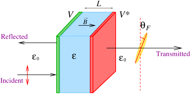
A linearly polarized electromagnetic plane wave with angular frequency enters the slab from the left at normal incidence propagating along the direction. The polarization direction of electric field of incident wave is taken as the z-axis: , where stands for the wave vector and denotes the dielectric constant of vacuum. A weak magnetic field , which preserves the linearity of Maxwell’s equations, is applied in the -direction and is confined into the slab, see Fig. 1. The scattering of incident wave by the dielectric slab is described by Schrödinger-like equations, see e.g. Refs. Gasparian et al. (1995); Lofy et al. (2020),
| (2) |
where are circularly polarized electric fields. The is defined by, see e.g. Refs. Gasparian et al. (1995); Lofy et al. (2020),
| (3) |
where is the gyrotropic vector along the magnetic-field direction. The external magnetic field is included into the gyrotropic vector to make the calculations valid for the cases of both external magnetic fields and magneto-optic materials. The magnetic field causes the direction of linear polarization to rotate while light propagates through the medium. As a consequence, the electromagnetic wave is elliptically polarized and the major axis of the ellipse is rotated with respect to the original direction of polarization. The angle of Faraday rotation, , and the degree of ellipticity, , are defined by Gasparian et al. (1995); Lofy et al. (2020)
| (4) |
where and are the transmission coefficients and phase of transmission amplitudes, , of transmitted electric fields:
| (5) |
For the dielectric material with real value of permittivity, the scattering -matrix can be parameterized by two independent real scattering phaseshifts, . The transmission coefficients and phases are given in terms of scattering phaseshifts by
| (6) |
Hence both angles and are real and well defined. As discussed in Ref. Guo and Gasparian (2022), for the scattering with a complex potential in general, scattering phaseshifts become complex. Therefore, with a complex dielectric slab, both and are complex in general, and physical meaning of both angles become ambiguous.
In a -symmetric system, the parameterization of scattering -matrix now requires three independent real functions: two phaseshifts and one inelasticity, , see Ref. Guo and Gasparian (2022). The phases of a -symmetric system, , are still given by the sum of two real phaseshifts as in Eq.(6), thus it remains real. The transmission coefficients of -symmetric system also remain real but now depend on inelasticity as well,
| (7) |
Therefore, with balanced gain and loss, the reality of both Faraday rotation angles and is warranted in a -symmetric system. In Ref. Guo and Gasparian (2022), it is also shown that the generalized Friedel formula relates the derivative of sum of two phaseshifts, , to the integrated generalized density of states of the -symmetric system, which turns out to be real for a -symmetric system. Hence the reality of FR angles in a -symmetric system can also be understood based on the generalized Friedel formula. However, the positivity of generalized density of state in -symmetric systems is no longer guaranteed. Therefore the FR angles of -symmetric systems show an anomalous behavior becoming negative.
A simple -symmetric model:
We use in our calculations a very simple -symmetric model to illustrate the anomalous behavior of FR angles by putting two complex delta potentials at both ends of the dielectric slab with a positive and real permittivity ( and real),
| (8) |
We adopt this model because it lets us obtain quite easily the analytical expressions, and some techniques and conclusions that were developed in Refs. Gasparian et al. (1995); Lofy et al. (2020) can be applied directly in this work. The -symmetric double complex boundaries model is similar to the model by considering -symmetric complex dielectric permittivities of slab: for first half of slab and for another half. Both models can be solved relatively easily and analytically, and both show similar anomalous behaviors of FR angles. No significant difference between two models have been observed. The basis and physical reason for this conclusion is that the two-boundary model discussed in the manuscript can be considered as having two slabs with changeable thickness and potential force, so the delta potentials are the limit of the two finite potentials of a square. Hence we will simply present some results of double complex boundaries model, and it is sufficient to show anomalous behavior of Faraday rotation angles in -symmetric systems.
For weak magnetic field () and constant dielectric permittivity in the slab, the Faraday rotation angles in Eq.(4) can be evaluated in terms of perturbation expansion of the weak magnetic field. The leading order expressions are obtained in Refs. Gasparian et al. (1995); Lofy et al. (2020) and are given by
| (9) |
where is the refractive index of the slab. The and stand for the coefficient of transmission and the phase in the absence of the external magnetic field . The conclusion in Eq.(9) also apply to double complex boundaries model in Eq.(8). For the simple double complex boundaries -symmetric model, the transmission amplitude, , can be easily obtained by matching boundary conditions method. Hence we find
| (10) |
where
| (11) |
is the ”relative” impedance of the dielectric slab, and denotes the wave vector of propagating waves inside the dielectric slab. The transmission amplitude can also be obtained by the Green’s function approach Carpena et al. (1997). We remark that the Green’s function approach is a better tool for more sophisticated multilayer systems, which is based on the exact calculation of the Green’s function (GF) of a photon for a given dielectric permittivity profile . The GF approach is compatible with the transfer matrix method and has been widely used to calculate the average density of states over a sample, the energy spectrum of elementary excitations Carpena et al. (1997), or the characteristic barrier tunneling time Gasparian et al. (1996), among others. The coefficient of transmission and the phase are thus explicitly given by
| (12) |
We remark that unphysical units are adopted in this work for a simple model: the length of slab is used to sent up the physical scale, and carry the dimensions of and respectively. The is hence a dimensionless quantity.
Spectral singularities:
The resonance states with vanishing spectral width appear in non-Hermitian complex potential scattering theory and yield divergences of reflection and transmission coefficients of scattered states, which are usually referred as spectral singularities, see e.g. Refs. Mostafazadeh (2009b); Ahmed (2009); Longhi (2009). Therefore, near spectral singularities it should be expected a strong enhancement of both Faraday rotation angles. Specifically, for the double complex boundaries -symmetric model considered in this letter, the spectral singularities occur when both conditions, and , are satisfied. Hence the solutions of spectral singularities can be obtained by
| (13) |
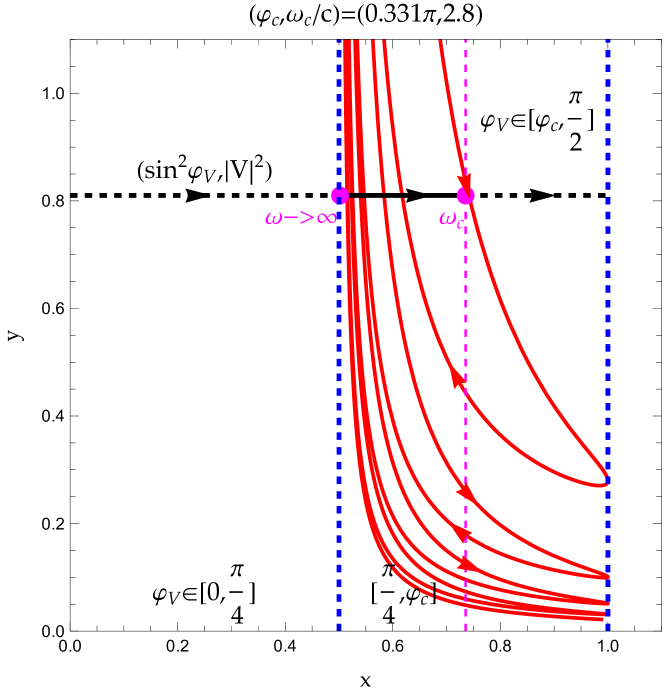
Since the left-hand side of the first condition in Eq.(13) is confined to the range , the spectral singularities exist only when the phase angle is in the range or . Henceforth, all discussions will be for the range: , which is sufficient due to the symmetry of our model.
The solutions of spectral singularities on real axis can be visualized graphically by observing the intersection of a curve and a line with coordinates given by both sides of Eq.(13) for a fixed , see Fig. 2 as a example. The curve that is plotted with coordinates given by left-hand side of Eq.(13) as function of is bound in the region with . For a fixed , the solutions of spectral singularities can only be found in a finite range: , where stands for upper bound of range, see e.g. Fig. 2. From Eq.(13), the spectral singularity solutions is related to by . Hence as approaches lower bound of range at , the spectral singularity solution occurs at large frequency: . When is increased, the solution of spectral singularity moves toward lower frequencies. As approaches the upper bound of range at , the spectral singularity solution thus reaches its lowest value at , see e.g. Fig. 2.
Phase transition-like phenomenon of Faraday rotation angle :
For a regular dielectric slab with positive and real permittivity ( and real), the Faraday rotation angle must be also real and positive. However, in a system, the Faraday rotation angle shows a phase transition-like anomalous behavior, and two phases are separated by model parameter :
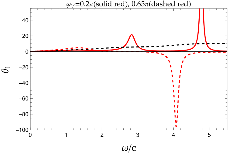
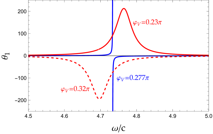
(Phase I) for , the value of is always positive. No spectral singularities can be found and -symmetric slab behaves just as a regular dielectric slab;
(Phase II) for , the value of may change the sign and turn negative. When , the spectral singularities occur and starts showing negative values. The negative only show up at large region when , and then gradually moves toward the lower frequency region as is increased. As continues increasing up to region of that is also free of spectral singularities, the negativity of persists, see e.g. Fig. 3.
Hence, a system yields a phase transition-like anomalous behavior of Faraday rotation angle , the is the critical value that separates the positivity and negativity phases of .
The phase transition-like behavior of can be understood intuitively by considering limiting case of ,
| (14) |
Now, we can see very clearly that the sign of is totally determined by in this limiting case.
The anomalous negativity behavior of can also be illustrated analytically at another limiting case by setting and ,
| (15) |
Both are positive definite functions, hence as , the sign of FR angle changes from positive to negative.
Discussion and summary:
In summary, using a simple -symmetric model with two complex -potential placed at both boundaries of a regular dielectric slab, we show that FR angles display a phase transition-like anomalous behavior. In regular phase, Faraday rotation angles behave as normal as in a regular dielectric slab. In anomalous phase, FR angle turns negative, and both angles and suffer spectral singularities and yield strong enhancement near singularities. The critical value of phase transition is controlled by the parameter of -symmetric model. A very similar anomalous phase transition-like behavior to FR is expected in reflected light (Kerr effect, see e.g. Ref. Lofy et al. (2020)).
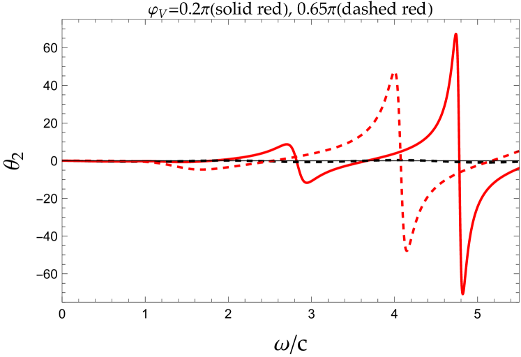
On the contrary to phase transition-like anomalous behavior during transition, angle doesn’t exhibit the significant change of nature except that it also suffers the spectral singularities in anomalous phase. This can be understood from the definition of in Eq.(4) and the expression of transmission coefficients in Eq.(7). The angle is an oscillating function regardless that dielectric slab is regular or -symmetric. In systems, the conservation law of scattering must be generalized, see e.g. Ref. Ge et al. (2015), the transmission coefficients are no longer bound in range of due to the inelasticity functions of systems . However, because angle depends only on the ratio of , the oscillating nature of remains unchanged even in systems with unbound . In addition, in both phases, we observe that vanish near frequencies of resonant peaks appeared in . The vanishing angle represents the purely linearly polarized wave with no ellipticity. The angle also displays the sawtooth behavior: the amplitude of angle keep growing as frequency is increased, and it is periodically repeated and changed sharply both in magnitude and in sign near the resonance frequencies.
As suggested in Ref. Guo et al. (2022), the phase transition-like behavior of is closely related to the motion of the pole of transition amplitudes. Near the pole, the transmission amplitude is approximated by
| (16) |
where is the pole position in complex -plane, see Eq.(24) in Guo et al. (2022). The phase of transmission amplitude is dominated by
| (17) |
The sign of is hence dictated by the position of the pole. For the regular dielectric slab or in normal phase of system, the poles remain in unphysical sheet and . However, in anomalous phase of system, poles cross the real axis and move into physical sheet with and negative near the pole. Therefore the sign of FR angle changes as the pole moves across the real axis from unphysical to physical sheet, and remains negative as long as poles stay in physical sheet. This can be easily illustrated in Fig. 5. For the set of model parameters chosen in Fig. 5, one of the spectral singularities is located at . For value slightly below , the pole is located in unphysical sheet, and remains positive. As value is increased across , the pole moves across the real axis into physical sheet, and hence changes sign and becomes negative.
We remark that for a simple model, the pole indeed yields divergent spectral singularities when it lies on the real axis. As discussed in Ref. Liu et al. (2014), in realistic systems, the divergence of spectral singularities may be regularized by nonlinearities of systems. Similarly, the regularization of singularities in a realistic system can also be achieved by imperfection of systems with a slight imbalance between the gain and loss regions by adding an infinitesimal parameter to imaginary part of the right boundary complex potential.
At last we remark that the reversal of the sign of the Faraday rotation also occurs in some other special cases. For example, in Ref. Dani et al. (2011), it was shown that near the plasmon resonance of nanoparticles solution, the Faraday rotation exhibits both left and right rotations for fixed frequencies. The latter is due to the change in the sign of the Verdet constant, as a result of increasing the thickness of the gold shell with the addition of a gold solution. As also mentioned in Ref. Sadatgol et al. (2016), the Faraday rotation angle can be increased and even changed its sign using metamaterials to adapt the optical properties of the host system. In addition, for the frequencies range where both complex permittivity and permeability have negative non-zero real parts and positive non-zero imaginary parts, the real part of turns out to be negative, see, e.g. Ref. Pendry (2004). Hence, the angle , which is an odd function with respect to the refractive index , will change the sign as well. As for , it is an even function of and does not change sign when is reversed Lofy et al. (2020). The phase transition-like behavior in the change of sign of the Faraday rotation angle in a system studied in this letter demonstrate a quite different mechanism from the cases mentioned above. The phase transition-like anomalous Faraday effect may be observed experimentally for the wider range of frequencies. Hence -systems seem to be ideal candidates for constructing fast tunable polarization rotational ultrathin magneto-optical devices.
Acknowledgements.
P.G. and V.G. acknowledge support from the Department of Physics and Engineering, California State University, Bakersfield, CA. V.G. and E.J. would like to thank UPCT for partial financial support through the concession of ”Maria Zambrano ayudas para la recualificación del sistema universitario español 2021-2023” financed by Spanish Ministry of Universities with financial funds ”Next Generation” of the EU. We also thank Christopher Wisehart for improving the use of the English language in the manuscript.References
- Landau and Lifshitz (1984) L. D. Landau and E. M. Lifshitz, Electrodynamics of Continuous Media (Pergamon, New York, 1984).
- Longair (2011) M. S. Longair, High Energy Astrophysics (Cambridge University Press, 2011), 3rd ed.
- Furdyna (1988) J. K. Furdyna, Journal of Applied Physics 64, R29 (1988), eprint https://doi.org/10.1063/1.341700, URL https://doi.org/10.1063/1.341700.
- Berger (2003) U. Berger, in Encyclopedia of Physical Science and Technology (Third Edition), edited by R. A. Meyers (Academic Press, New York, 2003), pp. 777–798, third edition ed., ISBN 978-0-12-227410-7, URL https://www.sciencedirect.com/science/article/pii/B0122274105004452.
- Turner and Stolen (1981) E. H. Turner and R. H. Stolen, Opt. Lett. 6, 322 (1981), URL http://opg.optica.org/ol/abstract.cfm?URI=ol-6-7-322.
- Firby et al. (2018) C. J. Firby, P. Chang, A. S. Helmy, and A. Y. Elezzabi, J. Opt. Soc. Am. B 35, 1504 (2018), URL http://opg.optica.org/josab/abstract.cfm?URI=josab-35-7-1504.
- Garbusi and Ferrari (2003) E. Garbusi and J. A. Ferrari, Optics & Laser Technology 35, 319 (2003), ISSN 0030-3992, URL https://www.sciencedirect.com/science/article/pii/S0030399203000100.
- Richard et al. (2000) N. Richard, A. Dereux, E. Bourillot, T. David, J. P. Goudonnet, F. Scheurer, and E. Beaurepaire, Journal of Applied Physics 88, 2541 (2000), eprint https://doi.org/10.1063/1.1288509, URL https://doi.org/10.1063/1.1288509.
- Uchida et al. (2011) H. Uchida, Y. Mizutani, Y. Nakai, A. A. Fedyanin, and M. Inoue, Journal of Physics D: Applied Physics 44, 064014 (2011), URL https://doi.org/10.1088/0022-3727/44/6/064014.
- Andrei and Mayergoyz (2003) P. Andrei and I. Mayergoyz, Journal of Applied Physics 94, 7163 (2003), eprint https://doi.org/10.1063/1.1625084, URL https://doi.org/10.1063/1.1625084.
- Gevorkian and Gasparian (2014) Z. Gevorkian and V. Gasparian, Phys. Rev. A 89, 023830 (2014), URL https://link.aps.org/doi/10.1103/PhysRevA.89.023830.
- Kaipurath et al. (2016) R. M. Kaipurath, M. Pietrzyk, L. Caspani, T. Roger, M. Clerici, C. Rizza, A. Ciattoni, A. Di Falco, and D. Faccio, Scientific Reports 6, 27700 (2016), URL https://doi.org/10.1038/srep27700.
- Pendry (2000) J. B. Pendry, Phys. Rev. Lett. 85, 3966 (2000), URL https://link.aps.org/doi/10.1103/PhysRevLett.85.3966.
- Yang et al. (2016) S. Yang, P. Liu, M. Yang, Q. Wang, J. Song, and L. Dong, Scientific Reports 6, 21921 (2016), URL https://doi.org/10.1038/srep21921.
- Caligiuri et al. (2016) V. Caligiuri, R. Dhama, K. V. Sreekanth, G. Strangi, and A. De Luca, Scientific Reports 6, 20002 (2016), URL https://doi.org/10.1038/srep20002.
- Cao et al. (2013) T. Cao, C. Wei, R. E. Simpson, L. Zhang, and M. J. Cryan, Opt. Mater. Express 3, 1101 (2013), URL http://opg.optica.org/ome/abstract.cfm?URI=ome-3-8-1101.
- Bender et al. (2019) C. M. Bender, P. E. Dorey, C. Dunning, A. Fring, D. W. Hook, H. F. Jones, S. Kuzhel, G. Lévai, and R. Tateo, PT Symmetry (WORLD SCIENTIFIC (EUROPE), 2019), eprint https://www.worldscientific.com/doi/pdf/10.1142/q0178, URL https://www.worldscientific.com/doi/abs/10.1142/q0178.
- Bender (2005) C. M. Bender, Contemporary Physics 46, 277 (2005), eprint https://doi.org/10.1080/00107500072632, URL https://doi.org/10.1080/00107500072632.
- Konotop et al. (2016) V. V. Konotop, J. Yang, and D. A. Zezyulin, Rev. Mod. Phys. 88, 035002 (2016), URL https://link.aps.org/doi/10.1103/RevModPhys.88.035002.
- Mostafazadeh (2010) A. Mostafazadeh, International Journal of Geometric Methods in Modern Physics 07, 1191 (2010), eprint https://doi.org/10.1142/S0219887810004816, URL https://doi.org/10.1142/S0219887810004816.
- Mostafazadeh (2009a) A. Mostafazadeh, Pramana 73, 269 (2009a), URL https://doi.org/10.1007/s12043-009-0118-4.
- El-Ganainy et al. (2018) R. El-Ganainy, K. G. Makris, M. Khajavikhan, Z. H. Musslimani, S. Rotter, and D. N. Christodoulides, Nature Physics 14, 11 (2018), URL https://doi.org/10.1038/nphys4323.
- Makris et al. (2008) K. G. Makris, R. El-Ganainy, D. N. Christodoulides, and Z. H. Musslimani, Phys. Rev. Lett. 100, 103904 (2008), URL https://link.aps.org/doi/10.1103/PhysRevLett.100.103904.
- Musslimani et al. (2008) Z. H. Musslimani, K. G. Makris, R. El-Ganainy, and D. N. Christodoulides, Phys. Rev. Lett. 100, 030402 (2008), URL https://link.aps.org/doi/10.1103/PhysRevLett.100.030402.
- BAGCHI et al. (2006) B. BAGCHI, S. MALLIK, H. BÍLA, V. JAKUBSKÝ, M. ZNOJIL, and C. QUESNE, International Journal of Modern Physics A 21, 2173 (2006), eprint https://doi.org/10.1142/S0217751X0602951X, URL https://doi.org/10.1142/S0217751X0602951X.
- Joglekar and Bagchi (2012) Y. N. Joglekar and B. Bagchi, Journal of Physics A: Mathematical and Theoretical 45, 402001 (2012), URL https://doi.org/10.1088/1751-8113/45/40/402001.
- Mostafazadeh (2009b) A. Mostafazadeh, Phys. Rev. Lett. 102, 220402 (2009b), URL https://link.aps.org/doi/10.1103/PhysRevLett.102.220402.
- Ahmed (2009) Z. Ahmed, Journal of Physics A: Mathematical and Theoretical 42, 472005 (2009), URL https://doi.org/10.1088/1751-8113/42/47/472005.
- Longhi (2009) S. Longhi, Phys. Rev. B 80, 165125 (2009), URL https://link.aps.org/doi/10.1103/PhysRevB.80.165125.
- Ge et al. (2012) L. Ge, Y. D. Chong, and A. D. Stone, Phys. Rev. A 85, 023802 (2012), URL https://link.aps.org/doi/10.1103/PhysRevA.85.023802.
- Hang et al. (2013) C. Hang, G. Huang, and V. V. Konotop, Phys. Rev. Lett. 110, 083604 (2013), URL https://link.aps.org/doi/10.1103/PhysRevLett.110.083604.
- Hang et al. (2014) C. Hang, D. A. Zezyulin, G. Huang, V. V. Konotop, and B. A. Malomed, Opt. Lett. 39, 5387 (2014), URL http://opg.optica.org/ol/abstract.cfm?URI=ol-39-18-5387.
- Alaeian and Dionne (2014a) H. Alaeian and J. A. Dionne, Phys. Rev. A 89, 033829 (2014a), URL https://link.aps.org/doi/10.1103/PhysRevA.89.033829.
- Alaeian and Dionne (2014b) H. Alaeian and J. A. Dionne, Phys. Rev. B 89, 075136 (2014b), URL https://link.aps.org/doi/10.1103/PhysRevB.89.075136.
- Zhu et al. (2014) X. Zhu, H. Ramezani, C. Shi, J. Zhu, and X. Zhang, Phys. Rev. X 4, 031042 (2014), URL https://link.aps.org/doi/10.1103/PhysRevX.4.031042.
- Gasparian et al. (1995) V. Gasparian, M. Ortuño, J. Ruiz, and E. Cuevas, Phys. Rev. Lett. 75, 2312 (1995), URL https://link.aps.org/doi/10.1103/PhysRevLett.75.2312.
- Lofy et al. (2020) J. Lofy, V. Gasparian, Z. Gevorkian, and E. Jódar, REVIEWS ON ADVANCED MATERIALS SCIENCE 59, 243 (2020), URL https://doi.org/10.1515/rams-2020-0032.
- Guo and Gasparian (2022) P. Guo and V. Gasparian, Phys. Rev. Research 4, 023083 (2022), URL https://link.aps.org/doi/10.1103/PhysRevResearch.4.023083.
- Carpena et al. (1997) P. Carpena, V. Gasparian, and M. Ortuño, Zeitschrift für Physik B Condensed Matter 102, 425 (1997), URL https://doi.org/10.1007/s002570050307.
- Gasparian et al. (1996) V. Gasparian, T. Christen, and M. Büttiker, Phys. Rev. A 54, 4022 (1996), URL https://link.aps.org/doi/10.1103/PhysRevA.54.4022.
- Ge et al. (2015) L. Ge, K. G. Makris, D. N. Christodoulides, and L. Feng, Phys. Rev. A 92, 062135 (2015), URL https://link.aps.org/doi/10.1103/PhysRevA.92.062135.
- Guo et al. (2022) P. Guo, V. Gasparian, E. Jódar, and C. Wisehart (2022), eprint 2208.13543.
- Liu et al. (2014) X. Liu, S. D. Gupta, and G. S. Agarwal, Phys. Rev. A 89, 013824 (2014), URL https://link.aps.org/doi/10.1103/PhysRevA.89.013824.
- Dani et al. (2011) R. K. Dani, H. Wang, S. H. Bossmann, G. Wysin, and V. Chikan, The Journal of Chemical Physics 135, 224502 (2011), eprint https://doi.org/10.1063/1.3665138, URL https://doi.org/10.1063/1.3665138.
- Sadatgol et al. (2016) M. Sadatgol, M. Rahman, E. Forati, M. Levy, and D. Ö. Güney, Journal of Applied Physics 119, 103105 (2016), eprint https://doi.org/10.1063/1.4943651, URL https://doi.org/10.1063/1.4943651.
- Pendry (2004) J. Pendry, Contemporary Physics 45, 191 (2004), eprint https://doi.org/10.1080/00107510410001667434, URL https://doi.org/10.1080/00107510410001667434.