IEC-61850 Performance Evaluation in a 5G Cellular Network: UDP and TCP Analysis
Abstract
This chapter summarizes the results obtained from a test bed, which is composed of a microgrid and a wireless network, both relying on real and practical premises. This test bed aims to evaluate application protocols considered in the transport layer of the standard IEC-61850. The application is a data gathering system, where IEC-61850 messages are transmitted from and between different elements in a microgrid system, such as IEDs, publishers, and subscribers, which are node elements that are part of the utility grid. The standard IEC-61850 defines many protocols, such as SV, GOOSE, and MMS, each of them with a variety of requirements and sharing similar transport communication protocols, such as TCP and UDP. Hence, a testing framework is used in the test bed in order to evaluate the performance of these protocols aiming to enable the communication in a real microgrid deployment. The IEC-61850 messages transported by TCP or UDP are transmitted to a centralized location, where a local database stores the information under different test scenarios and using different transmission sample times. The overall results are promising and indicate that the protocols based on TCP in combination with a 5G cellular network architecture would be suitable for most applications within the studied microgrid case. In the case of UDP, the performance indicated some specific constraints related to the multiple access nature of simultaneous transmissions and also based on the SINR .
Keywords— IEC61850, 5G, LVDC, microgrid, cellular network
- 1G
- first generation of mobile network
- 1PPS
- 1 pulse per second
- 2G
- second generation of mobile network
- 3G
- third generation of mobile network
- 4G
- 4th generation of mobile network
- 5G
- 5th generation
- ARQ
- automatic repeat request
- ASIP
- application specific integrated processors
- AWGN
- additive white Gaussian noise
- BER
- bit error rate
- IP
- Internet protocol
- MAC
- media access control
- LTE
- long-term evolution
- EPS
- Evolved Packet System
- EPC
- Evolved Packet System
- E-UTRAN
- Evolved UTRAN
- eNB
- evolved Node B
- OFDMA
- Orthogonal Frequency Division Multiple Access
- SC-FDMA
- Single Carrier Frequency Division Multiple Access
- 3GPP
- 3rd Group Partnership Project
- SNR
- signal to noise-ratio
- BPSK
- binary phase shift keying
- AWGN
- additive white Gaussian noise
- PER
- packet error ratio
- WLLN
- weak law of large numbers
- probability density function
- MCS
- modulation and coding scheme
- UE
- user equipment
- PGW
- packet data network gateway
- SGW
- serving gateway
- PHY
- physical layer
- HARQ
- hybrid automatic repeat request
- RLC
- Radio link control
- PDCP
- Packet data convergence protocol
- ROHC
- robust header compression
- RRC
- radio resource control
- SIB
- system information block
- NAS
- non-access stratum
- MME
- mobility management entity
- CEI
- consumer-end inverter
- IPC
- industrial personal computer
- PV
- photo-voltaic
- FO
- fibre optic
- BESS
- battery energy storage system
- RS
- rectifier substation
- ICT
- information and communication technology
- IT
- terrian-isolated functionalities unearth grounding
- KPI
- key performance indicator
- CPE
- customer premise equipment
- IED
- industrial electronic device
- PDN
- packet data network
- MMS
- manufacturing message specification
- GOOSE
- generic object-oriented substation event
- SV
- sampled value
- MIMO
- multiple input multiple output
- EPC
- evolved packet core
- ICMP
- Internet control message protocol
- UDP
- user datagram protocol
- TCP
- transmission control protocol
- RSRP
- reference signal received power
- RSRQ
- reference signal reference quality
- SINR
- signal to noise ratio
- RSSI
- received signal strength indication
- WAN
- wide area network
- RES
- renewable energy source
- DSO
- distribution system operator
- RAN
- radio access network
- LAN
- local area network
- LVDC
- low-voltage direct current
1 Introduction
The impact of cellular networks on society has been defined by the evolution of wireless communication technologies, which have been applied for many generations. Most of these developments have focused on human applications. However, nowadays, cellular networks aim to support many industrial or vertical applications, such as energy systems, grid automation, mining industry, and process automation industry.
1.1 Evolution of Power System Industry
Traditional power grids with unidirectional power flow are being transformed into bidirectional flow, which is related to the increasing amount of distributed generation and energy storage units connected to the grid. In other words, the traditional end consumers are being replaced by prosumers, which are end users that both consume and generate energy. These new elements have brought up attractive and interesting use case scenarios in microgrid systems. For instance, some parts of electricity distribution networks that are connected to grids are able to run in the islanded mode (a microgrid is said to be in the islanded mode when it is disconnected from the main grid and it operates independently with micro sources and load). In other cases, renewable energy sources in power grids, such as weather-dependent wind and solar power generation, as well as the energy storage distributed to power systems, increase the need for having more monitoring, control, and protection applications that support the requirements of grid automation. Accordingly, these grid applications set more stringent requirements for the communication networks enabling data exchange between different nodes in the grid and between the grid and the remote systems of distribution system operators.
Nowadays, these applications are run on wired networks, such as power line communication and fibre optic networks, which are mostly based on the Ethernet protocol. For instance, fibre optic networks are used in the automation of substations and also to connect two different substations, in which the communication network is used as a backhaul between networks, for example for connectivity between two remote monitoring rooms of two different DSOs.
1.2 Evolution on Cellular Network Industry
Likewise, the power grid evolution in the last decade, that is, the 4th generation of mobile network (4G), revolutionized the cellular network industry because it was the first system supporting an end-to-end packet-switched network; for instance, voice calls can be made using a full Internet protocol (IP) network. The improvements of a variety of features in the protocol stack enabled connectivity between devices and applications on a diversity of industrial applications. However, most of the critical applications are still being supported by wired solutions. In contrast to their wired counterpart, wireless connectivity offers scalability, flexibility, and cost efficiency because it reduces the need for expensive wires and installation costs.
Today, wired networks are popular because the microgrid and energy system domains set special requirements for communications, such as latency, reliability, availability, and throughput. For example, failures or anomalies in data delivery can cause severe damages in the control and automation used in microgrids.
1.3 State of the Art
The state-of-the-art research includes many studies which aim to address the performance evaluation of specialized protocols, such as IEC-61850 over a private LTE network described in Eriksson (2017). Here, a prototype emulates an industrial electronic device (IED), which was derived from an IEC-61850-90-5 open-source project. In this work, different metrics, such as reliability, availability, latency, and throughput, were evaluated. Based on a simulation analysis, the authors of Karagiannis et al. (2014) investigated whether long-term evolution (LTE) can be used in combination with IEC-61850 and manufacturing message specification (MMS) to support smart metering and remote control communication. In Musaddiq et al. (2014), a substation automation system was modeled and simulated under a wireless and hybrid network for three types of message, viz. generic object-oriented substation event (GOOSE), sampled value (SV), and interbay trip messages. The authors conclude that when circuit breakers were connected wirelessly, trip messages had high delays. Many other works provide similar performance evaluations (Kheaksong et al. (2016); Parikh et al. (2010)). However, most of them only address ideal scenarios using simulations.
In contrast to the current state of the art, the results reported in this chapter are considered fully realistic scenarios, which are represented by real rural microgrid users and a practical deployment of a private cellular network that is based on a 5th generation (5G) architecture that involves the application of edge computing to reduce the backhaul latency. It also considers true radio propagation with a diversity of wireless networking impairments. This condition makes the output of this work unique.
2 Test Bed Description
The main elements of the test bed are composed of the wireless communication network and the low-voltage direct current (LVDC) microgrid pilot.
2.1 Wireless Communication
The connectivity used in the field test bed is based on a 5G architecture, which is mostly characterized by the utilization of an edge-computing implementation of the core network to avoid latency impairments between the radio access network (RAN) and the core network, which is managed remotely through the cloud. The RAN is based on LTE-Advanced, which is operating in Band 40 with a bandwidth of 20 MHz.
The architecture of the wireless cellular network is based on an end-to-end private wireless network with an edge-computing platform. It aims to support real-time applications for industrial applications. Compared with a traditional 4G cellular network, the architecture of the network deployed in the field has an edge server, where the main core network server elements are deployed. This edge-computing core network is capable of being configured remotely from anywhere on the Internet. However, as it is the edge, the latency constraints in the core network are avoided. Thus, only the wireless access network represents the most important source of degradation when the latency is the key performance indicator (KPI).
The customer premise equipment (CPE) is compliant with the downlink category 15 and the uplink category 13 of the 3rd Group Partnership Project (3GPP) specifications. Hence, the radio supports downlink carrier aggregation with 256 QAM and 2x2 multiple input multiple output (MIMO) technology, and the uplink single carrier with 64 QAM 2x2 MIMO. Each CPE has a fixed beam antenna with up to a 12.5 dBi gain and a power transmission of 23 dBm. The base station operates with a power transmission of 35 dBm with an omnidirectional antenna with a gain of 4 dBi.
2.2 LVDC Microgrid Pilot
The LVDC microgrid field pilot is part of a local distribution network owned by a Finnish energy company Suur-Savon Sähkö Oy (SSS Oy) and operated by its subsidiary distribution company Järvi-Suomen Energia Oy. The platform has been implemented in collaboration with Lappeenranta University of Technology (LUT) as part of the Finnish national Smart Grids and Energy Markets research program.
The system is designed to meet flexible testing needs and has exhaustive distribution system functionality. The pilot is implemented according to the national low voltage standard series SFS 6000 based on HD 60364, IEC 60364, and IEC 60664. The voltage quality requirements were set based on the EN 50160 standard, but some limit values were changed as reported in Nuutinen et al. (2013).
2.2.1 Architecture
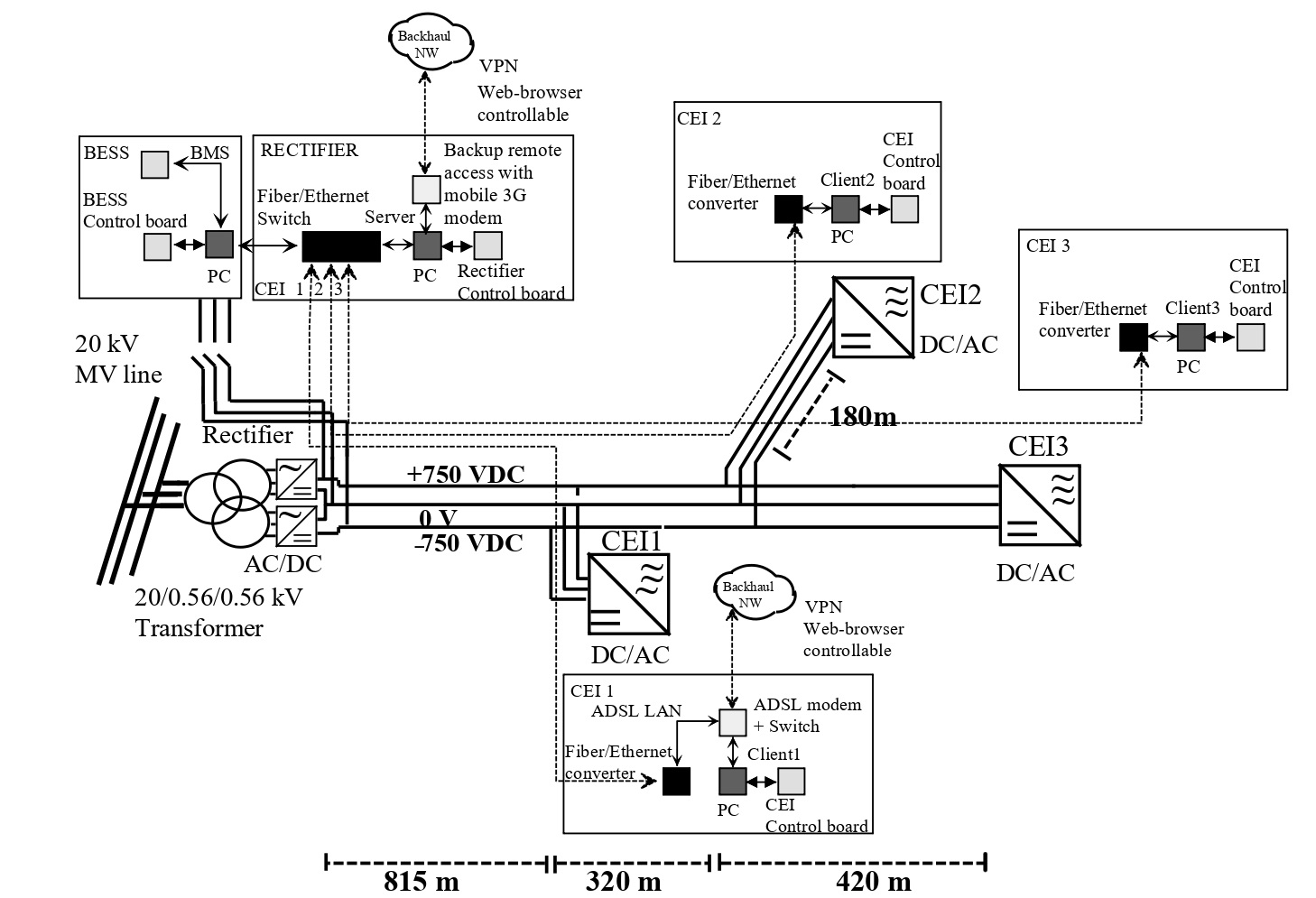
The LVDC pilot has a structure following the concept of the LVDC distribution system. Figure 1 presents the grid configuration of the pilot. The setup consists of a 70 kVA-rectifying substation, supplied with a double-tier transformer from a 20 kV MV network, a battery energy storage system (BESS), comprising 2 x 30 kWh-nominal capacity sections, 2 x 35 kVA converters and a 100 kVA transformer, a 1.7 km-long underground-cabled bipolar ±750 V DC network, three 16 kVA consumer-end inverters, and a photo-voltaic (PV) array, which is currently out of operation. Two CEIs are connected to the plus pole of the ±750 V DC network, and one CEI is connected to the negative. The CEIs supply four end consumers with three-phase 230/400 V AC voltage. The third CEI supplies two end users as their consumption is lower than the nominal power of the inverter. CEIs have a three-phase structure with galvanic isolation that allows the use of terrain-isolated functionalities of unearthed (IT) grounding in the DC distribution grid with the functionality of earthed (TN) grounding of the end consumer, which is typically used in Finland: for further details, the reader is referred to Nuutinen et al. (2014).
The system is normally operated in the grid connection mode. However, in case of MV supply interruption, it is switched into the island operation mode, where CEIs are supplied from the BESS. The voltage variation in the DC grid is kept within +10% -20% during normal operation and -30% in the isolated operation mode. The end consumers have 50±0.2% of frequency variation, ±1% in normal operation and ±15% in island mode operation; voltage variations are used according to Kaipia et al. (2012).
2.2.2 Application
Figure 2 illustrates the network structure with a wired fibre optic (FO) communication network, installed alongside LVDC underground cables. FO is a single-mode multicore fibre with 16 cores. CEIs are connected with a rectifier with a core per connection. The information and communication system of the pilot is implemented with a Linux-based industrial personal computer (IPC) and has a client-server architecture. Each CEI has an IPC: the model is Matrix 522, which is connected with a measurement card and applies monitoring, control, data logging, and web–client functions. The solar plant is equipped with another model of IPC (Matrix504), which provides functionality similar to that of CEI devices. The BESS control and monitoring, server, and database are implemented on an IPC placed at the rectifier substation (Lana et al. (2015)). The server has the following functionalities: data gathering from all client applications, gateway of remote connection, updates of the web portal, data logging, control of CEIs, and data transfer to the remote database. The collected data are also stored in the local database, located at the SSD connected to the database IPC.
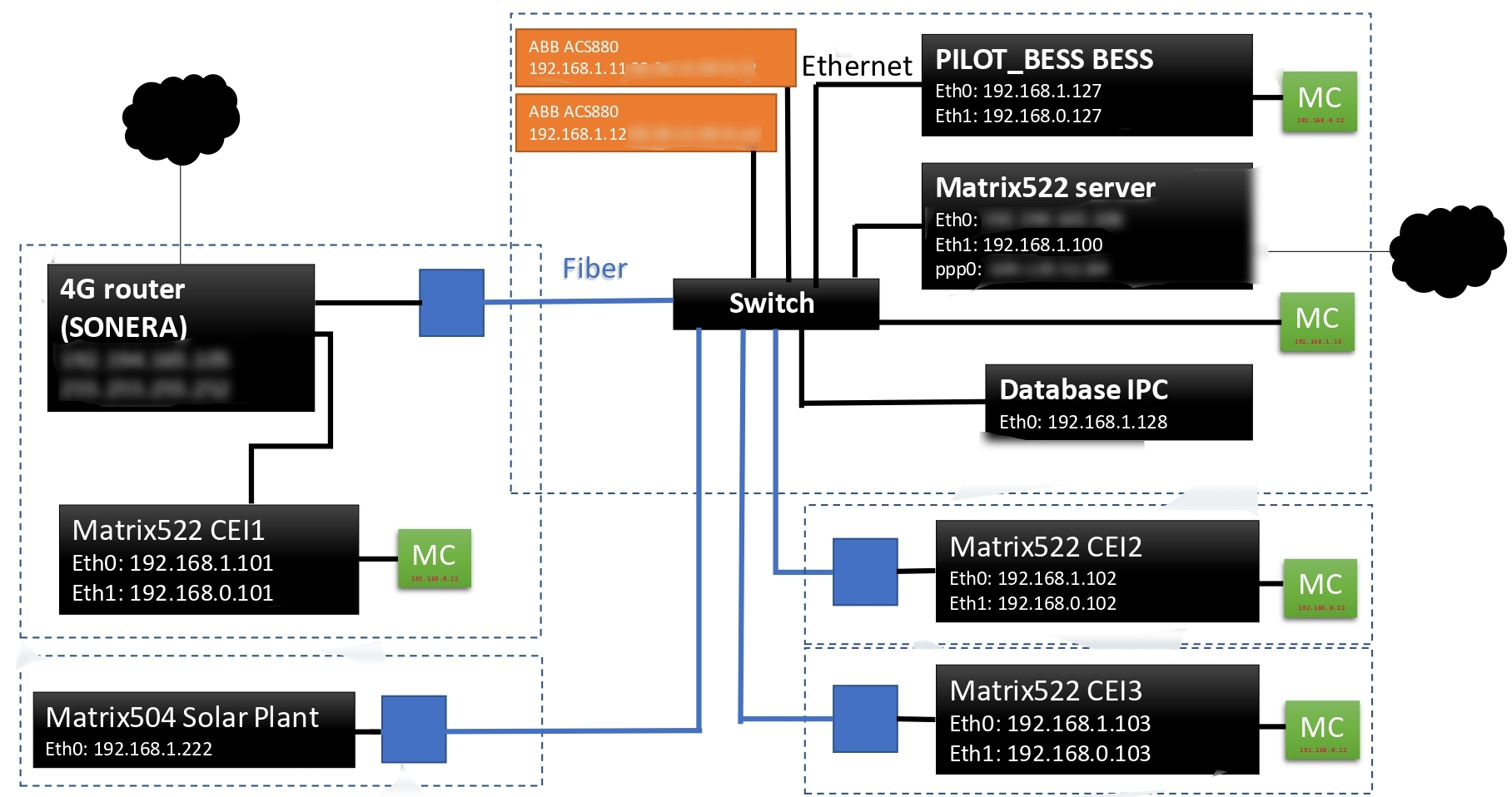
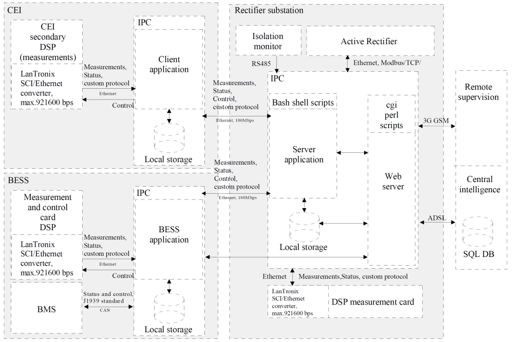
Figure 3 illustrates the architecture of the information and communication technology (ICT) system of the pilot, showing the monitoring and control solutions. The web portal provides remote control and uninterrupted monitoring of the system. All supervised data are presented on the portal and logged and stored locally. The web portal allows to monitor the following operation monitoring functions ( Lana et al. (2015)):
-
•
Statuses of the network and its components
-
•
Power flow monitoring—the data consist of minimum, maximum, and average power, voltage and current values with one-minute resolution.
-
•
Power quality monitoring—includes harmonic content, defined by the fast-Fourier transform (FFT) and power quality indices. The measurement intervals are 16 and 18 s for the CEIs and the rectifier, respectively.
-
•
System supervision portal—allows access to the pilot without installation of additional software. The update rate of the web portal is 10 s.
-
•
Fault identification—records the fault code and the corresponding measurements window of current and voltages with time stamps and notifies the support personnel. The measurements of currents and voltages are applied at the rectifier substation.
-
•
Network rectifier station—controls and monitors over a network front-end rectifier, which is required to ensure reliable network operation.
- •
-
•
CEI control diagnostic—is designed to meet the requirements of the public network, actual end users, and research.
2.3 Test Bed Objectives
The main objective of this test bed is to benchmark and evaluate the performance of a real private cellular network located in the rural area of Suomenniemi (southern Finland), where a microgrid pilot provides power supply to local citizens. The objectives of this study are the following:
-
•
Evaluate the system performance of a cellular network that is based on a 5G architecture using an edge core network to reduce potential impairments on the backhaul between the radio and core networks.
- •
-
•
Evaluate the system performance in terms of throughput and latency in different scenarios, such as data rate, simultaneous traces for transmission control protocol (TCP), and user datagram protocol (UDP) packages.
- •
-
•
Generate a radio coverage mapping based on measurements obtained in the field and a temporal analysis of typical LTE metrics, such as received signal strength indication (RSSI), reference signal received power (RSRP), RSRP, and signal to noise ratio (SINR) in each point where the LTE CPEs are installed.
3 IEC-61850
The preparation of IEC 61850 began in 1995 in the United States. Initially, the work was done by two independent, parallel working groups: The first one is the UCA International Users Group, developing a common object model of substation equipment (GOMFSE); the second was formed within the framework of the IEC Technical Committee 57 and was engaged in the creation of a standard of data transmission protocols at a substation. In 1997, the work of both groups was combined under the auspices of Working Group 10 of IEC TC 57 and became the basis of the IEC 61850 standard.
The standard is based on the following statements:
-
•
Technological independence, i.e., regardless of technological progress, the standard should be subject to minimal changes over time;
-
•
Flexibility, i.e., it should allow for different tasks to be solved using the same standardized mechanisms;
-
•
Extensibility, i.e., meeting the requirements, the standard allows to meet the changing needs of the electric power industry and use the latest advances in computer, communication, and measurement technologies.
The main features of IEC-61850:
-
•
It defines not only how, but also what information should be exchanged. The standard describes abstract models of the object’s hardware and the functions performed. The information model underlying the standard is presented in the form of classes of data objects, data attributes, abstract services, and descriptions of the relationships between them;
-
•
It defines the system design and setup process;
-
•
It defines the system configuration description language (SCL). This language provides the ability to exchange information about the configuration of devices in a standardized format between software from different manufacturers;
-
•
It describes the methods of testing and acceptance of equipment.
The key aspect of IEC-61850 defined before is the definition of a three-level automation system architecture, which comprises the following: the process level, the bay level, and the station level.
The process level includes sensors, remote I/Os, and actuators. The bay level consists of control, protection, and monitoring intelligent electronic devices (IED). The station level comprises the station computer with databases, the operators’ user interfaces (UI), and remote communication.
The standard has an object-oriented approach that allows to establish logical communication among IED, a merging unit (MU), and the system operator.
Initially, the standard defined only an automation system within a single object, and the links between substations were not included in the model. In 2012, IEC-61850 was expanded with parts 90-1 and 90-5. The updated model presented the communication system architecture described in the second edition of the standard, which also provides connections between substations. The structure of information exchange is described between the levels, as well as within each of them. These parts allow the expansion of the communication standardization beyond substation limits and make it possible to apply the standard also to smart grids.
IEC-61850 defines three key communication protocols to implement data exchange within and between defined levels:
- •
- •
- •
3.1 MMS
Part 8-1 of IEC 61850 describes the MMS (Manufacturing Message Specification) protocols used for data exchange for which time delay is not critical. They operate on the full OSI model on top of the TCP stack, which means that data transmission over this protocol is carried out with relatively large time delays. For example, this protocol can be used to send remote control commands, collect telemeasurement and telesignaling data, and send reports and logs from remote devices. The detailed presentation of the protocol can be found in Typhoon (b). The MMS defines the following:
-
•
A set of standard objects on which operations are performed that must be present in the device (e.g., reading and writing variables, signaling events);
-
•
A set of standard messages that are exchanged between the client and the server for control operations;
-
•
A set of rules for encoding these messages (how values and parameters are assigned to the corresponding bits and bytes when forwarding);
-
•
A set of protocols (rules for exchanging messages between devices).
Therefore, the MMS protocol itself is not a communication protocol: it only defines the messages that should be transmitted over a specific network. As a communication protocol, MMS uses the TCP/IP stack, and thus, it belongs to the transport layer of the OSI model.
3.2 GOOSE
Part 8-1 also describes the GOOSE protocol as a UDP publisher/subscriber-type communication. Typhoon (a) describes the details of the protocol and its application. The information content of this protocol is defined in IEC 61850-7-2. There is a description of the protocol syntax, the definition of the data assignment of an Ethernet frame in accordance with ISO/IEC 8802-3, and the procedures related to the use of this frame. Because the data in this protocol are assigned directly to the Ethernet frame, bypassing the TCP stack, the data transmission in it is carried out with significantly lower time delays compared with MMS. This allows the GOOSE protocol to be used to transmit commands to disconnect the circuit breaker from the protection and other signals for which the time delay is critical. Initially, the data sets are grouped for their subsequent sending using the GOOSE protocols. Then, in the GOOSE-sending control unit, a reference to the created dataset is specified: in this case, the publisher knows exactly what data to send. Within the framework of a single GOOSE message, both one value (e.g., the overcurrent protection trigger signal) and several values can be sent simultaneously (e.g., the start and overcurrent protection trigger signals). The subscriber can extract from the packet only the data that it needs. The transmitted GOOSE message packet contains all the current values of the data attributes entered in the dataset. If any of the attribute values change, the device immediately initiates sending a new GOOSE message with the updated data.
3.3 SV Messages
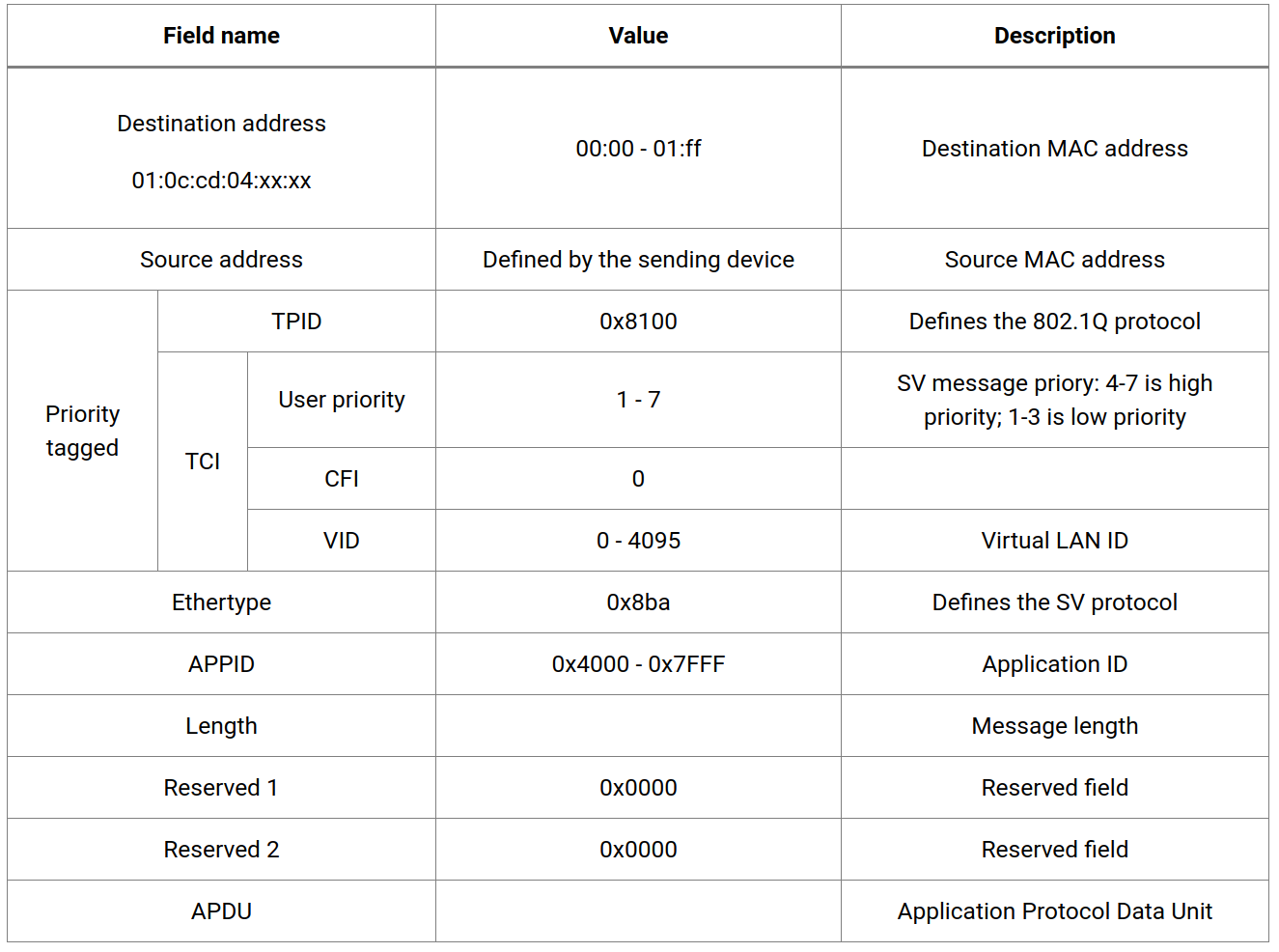
The SV protocol, defined in IEC-61850 9-2, is used to transmit measured values from the process to the bay level with a predefined time interval within a power facility. The protocol is described in detail in Typhoon (c). The data transmission is critical to the latency and should have a high bandwidth. The time interval depends on the measured signal frequency and Samples Per Period (SPP). Part 9-2LE of IEC618950 defines two possible SPPs in 80 and 256 samples. Therefore, for example, for the frequency of 50 Hz, the time interval will be equal to . The maximum delay for SV multicast data transmission is (Cisco (2019)). Figure 4 illustrates the structure of an SV message. The APDU field contains the payload of the SV messages. Every APDU (Application Protocol Data Unit) contains up to eight ASDUs (Application Specific Data Units), where each ASDU has a unique SV identification value and contains one three-phase current and voltage measurements.
3.4 R-SV, R-GOOSE
SV and GOOSE protocols are defined in IEC-61850 9-2 and 8-1, respectively. Both operate in a publisher/subscriber mode over layer 2 in a generic network protocol stack. As a consequence, the data transmission is limited to local area networks. There are two options to transmit GOOSE or SV messages over a wide area network (WAN) (Ustun et al. (2020)). The first one is tunneling messages over a high-speed network, such as SDH or SONNET. The second option is application of Routable-SV/GOOSE (R-SV/R-GOOSE) defined in the extended version of the protocols (IEC-61850-90-5) by adding a network and transport layer. The first option is less preferable as it leads to employment of a gateway, and message exchange is carried out in a point to point manner. R-SV messages, in turn, can be multicasted in WANs. The R-SV protocol also includes a Group Domain of Interpretation (GDOI) security mechanism for protecting data transmission Ustun et al. (2020).
3.5 Summary of the Standard IEC-61850
IEC 61850 is an Ethernet-based international standard, which has become the standard for communication at many energy facilities and substations. The IEC 61850 standard is aimed to integrate all protection, control, measurement, and monitoring functions into the energy facilities. The control monitoring and protection functions are placed at the IED: the measurement one is applied with an MU. Figure 5 illustrates the structure of the protocol application.
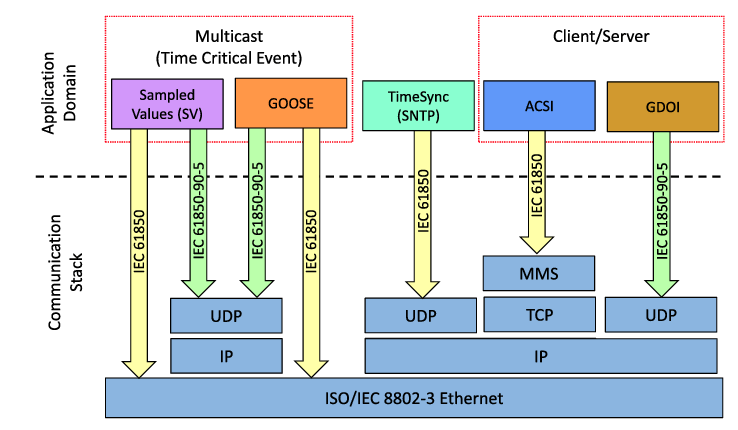
Figure 5 illustrates the structure of the protocol application. MMS is a TCP client/server-based protocol used for non-time-critical control signals. GOOSE is a UDP publisher/subscriber-based protocol applied for the transmission of time-critical control and protection-related data. SV is a UDP publisher/subscriber-based protocol utilized, for instance, for measurement data exchange with a constant sampling frequency. The latency and bandwidth are critical for SV data transmission. GOOSE and SV can be used only within LAN. R-GOOSE and R-SV are extension versions of the protocols that allow transmission of data over WAN. Therefore, IEC-61850 can be used not only within substations but also for smart grids. MMS is a TCP client/server-based protocol used for non-time-critical control signals; GOOSE is a UDP publisher/subscriber-based protocol applied for the transmission of time-critical control and protection-related data; and SV is a UDP publisher/subscriber-based protocol used for measurement data exchange with a constant sampling frequency. The latency and bandwidth are critical for SV data transmission. Furthermore, GOOSE and SV can be used only within LAN. R-GOOSE and R-SV are extension versions of the protocols that allow transmission of data over WAN. Therefore, IEC-61850 can be used not only within substations but also for smart grids MESIDAS .
4 Test Bed Setup and Tools
4.1 Deployment
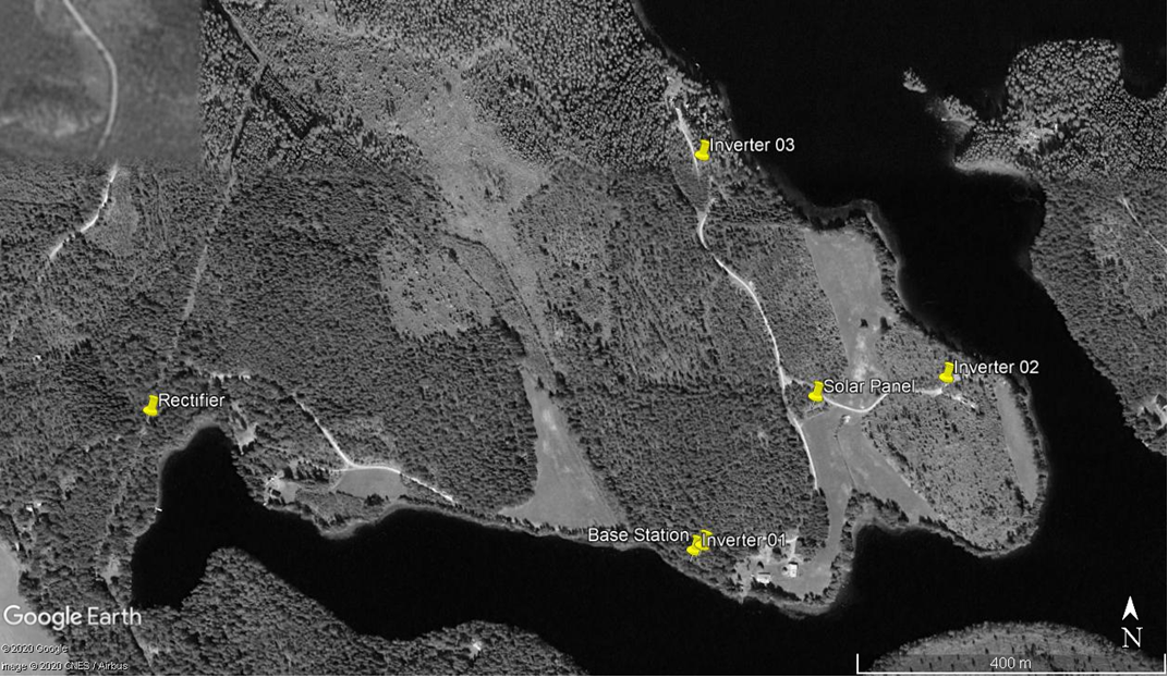
The microgrid is running in Suomenniemi (southern Finland), which is a small community with a high forest density and some challenging elevations that generate impairments in the radio propagation. Figure 6 visualizes the elements of the network. In each microgrid element, one CPE is installed.
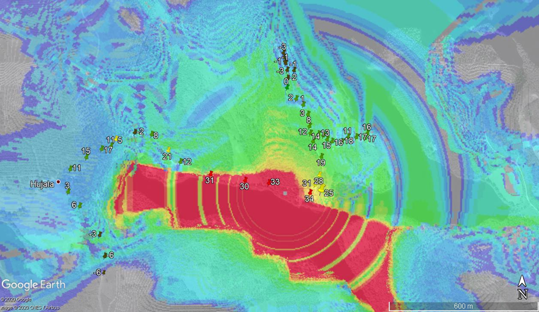
During the deployment, a preanalysis was conducted based on a radio propagation prediction of the network coverage. This radio coverage prediction was made using a simplified link budget that depends of the power transmission, antenna gain, and height location of antennas. The output of this analysis is presented in Figure 7. In the case of the base station, the antennas were installed above 25 m and the CPEs to an average height of 3 m.
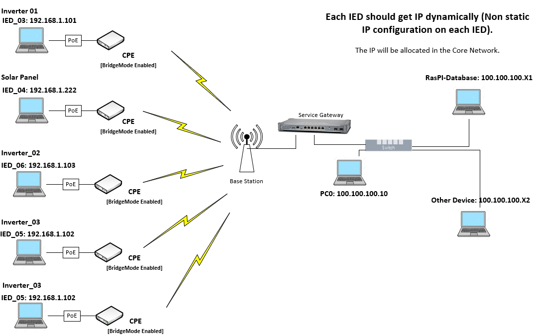
The test setup is composed of a base station, which is compliant with the LTE-advanced specifications, an evolved packet core (EPC), which is compliant with 5G architectures using edge computing specifications, and five CPEs, which are the capillary access of the network. One computer, named PC0, is connected to the core routing unit, and each CPE is connected to one embedded system, as shown in Figure 8. To avoid routing issues on the network, the bridge mode was enabled in each CPE.
The tool used to evaluate the throughput is IPERF Dugan (2010). There are many testing configuration setups that are evaluated using an automatic Python script, which was used to manage the measurements to be made in the network.
The scripts used in this stage are publicly available in the following repository:
https://github.com/aikonbrasil/NetMeter.
4.1.1 Database Description
Figure 9 illustrates the structure of the local database where data gathered from all applications are stored. The database is placed on the interconnection of SSD and Raspberry Pi 4 and located at the rectifier station. It contains eleven tables, where each table includes data related to the specific LVDC grid application. The database is used in the testing as a source for creating emulated data packages. As the rectifier substation (RS), the BESS, and the database are located at the same place, the data from the corresponding tables are not used in testing as the IPCs of these devices and the database have a wired connection that is not replaced with a wireless system. CEIs and solar installations are under a wireless connection through CPEs; therefore, the data from the CEIs and the solar applications can be used for testing. However, because the PV array was out of operation at the moment of testing and only a small part of the information was available from that installation, only data from CEI-related tables were used in testing.
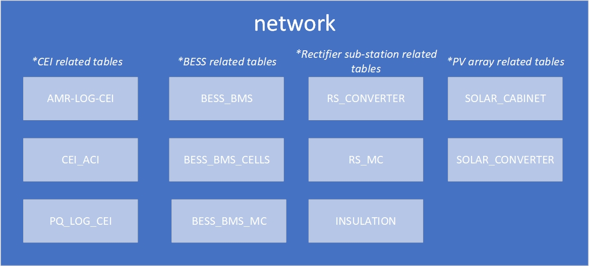
There are four groups of tables related to the different equipment: CEI, BESS, RS, and PV. The BESS group comprises three tables: BESS_BMS, where data from the battery management system are collected (e.g., total voltage, total current, state of charge); BESS_BMS_CELLS, where data about cells are included (e.g., cell id, cell voltage, cell temperature); and BESS_BMS_MC, which contains information from the measurement card of the BESS (e.g., BESS grid voltage, BESS grid current, BESS power). Another group is related to the rectifier and comprises three tables: RS_CONVERTER, where general data about the converter are gathered (e.g., power, line current, DC voltage); RS_MC including information from the measurement card of the rectifier station (e.g., grid voltages and currents, FFT and THD of currents); and INSULATION table that comprises alarm and fault-related logs. As CEI tables are used in testing and PV-related tables can be used after returning PV into operation, a more detailed description of the attributes of the tables is presented in Tables 1–3.
| Table name | Column name | Description |
|---|---|---|
| ARM_LOG_CEI | TIMESTAMP | Time on the client side |
| ARM_LOG_CEI | CEI_ID | ID of the client (from which inverter data are sent) |
| ARM_LOG_CEI | U_DC | Input inverter voltage (before inverting), direct voltage |
| ARM_LOG_CEI | I_DC | Input inverter current (before inverting), direct current |
| ARM_LOG_CEI | U_RMS_A, U_RMS_B, U_RMS_C | Phase voltages on the inverter output side (3-phase inverter), alternate voltages (AC) |
| ARM_LOG_CEI | I_RMS_A, I_RMS_B, I_RMS_C | Phase currents on the inverter output side (3-phase inverter), currents voltages (AC) |
| ARM_LOG_CEI | S_RMS_A, S_RMS_B, S_RMS_C | Phase powers on the inverter output side (3-phase inverter), phase powers (AC) |
| ARM_LOG_CEI | T_IGBT | Temperature at the switches (internal inverter sensor) |
| ARM_LOG_CEI | T_AMBIENT | Temperature in the cabinet |
| ARM_LOG_CEI | STATUS_FLAGS | Based on this status, THD values are set to 0 or factual values. |
| ARM_LOG_CEI | FAULT_FLAGS | Flag shows if there are any faults on the inverter side |
| Table name | Column name | Description |
|---|---|---|
| CEI_ACI | TIMESTAMP | Time on the client side |
| CEI_ACI | CEI_ID | ID of the client (from which inverter data are sent) |
| CEI_ACI | T_L1, T_L2, T_W1, T_W2 | ACI box temperatures |
| CEI_ACI | R1-R6 | States of relays in the inverter ACI box |
| CEI_ACI | Connected | Connection state |
| PQ_LOG_CEI | TIMESTAMP | Time on the client side |
| PQ_LOG_CEI | CEI_ID | ID of the client (from which inverter data are sent) |
| Table name | Column name | Description |
|---|---|---|
| SOLAR_CABINET | TIMESTAMP | Time on the client side |
| SOLAR_CABINET | CABINET_ID | ID of the solar plant (there is only one in the system) |
| SOLAR_CABINET | Heater, fan | States of heating or cooling operation device |
| SOLAR_CABINET | CB | Current breaker state |
| SOLAR_CABINET | Tcabinet | Temperature in the solar cabinet |
| SOLAR_CABINET | Connected | Connection state |
| SOLAR_CONVERTER | TIMESTAMP | Time on the client side |
| SOLAR_CONVERTER | CABINET_ID | ID of the solar plant (there is only one in the system) |
| SOLAR_CONVERTER | DCUPOWER | Ensto DC/DC converter internal power reference |
| SOLAR_CONVERTER | ActualPowerReference | actual power reference of the solar plant |
| SOLAR_CONVERTER | DC_Link_Current | Current in the DC link between the grid and the solar plant |
| SOLAR_CONVERTER | DC_Link_Power | Power in the DC link between the grid and the solar plant |
| SOLAR_CONVERTER | DC_Link_Voltage | Voltage in the DC link between the grid and the solar plant |
| SOLAR_CONVERTER | DC_Out_Current | Solar output current |
| SOLAR_CONVERTER | DC_Out_Power | Solar output power |
| SOLAR_CONVERTER | DC_Out_Voltage | Solar output voltage |
| SOLAR_CONVERTER | Temp1 ,Temp2 | Temperatures in a converter |
| SOLAR_CONVERTER | SetpointPowerReference | Set power reference for the solar plant |
| SOLAR_CONVERTER | MSW | Main status word |
| SOLAR_CONVERTER | Fan | Cooling state |
| SOLAR_CONVERTER | Connected | Connection state |
5 Measurement Procedure and Results
Three different procedures were applied in the measurements. The first one is based on an isolated and simultaneous analysis of the TCP and UDP protocols between PC0 node and each of the embedded systems installed in each CPE; this analysis is done in terms of throughput. The second procedure is based on the analysis of the latency evaluated with the Internet control message protocol (ICMP). Finally, the third procedure focuses on the analysis of the application. Thus, the database information was emulated in each embedded system, following the sampling time in which the data are generated in the real IEDs. This information is transmitted via TCP and UDP to the embedded system that hosts the database. In this particular procedure, the data integrity was evaluated on the received side to obtain numerical values indicating potential package loss.
The results of each procedure are described in the following.
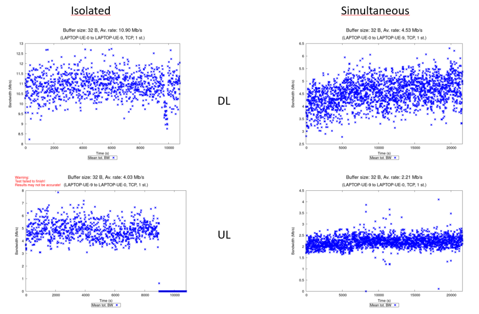
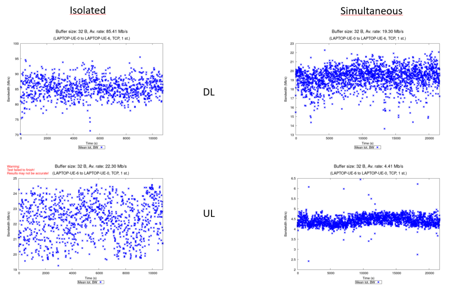
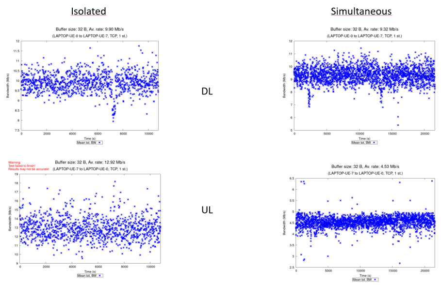
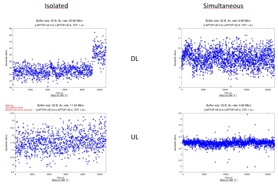
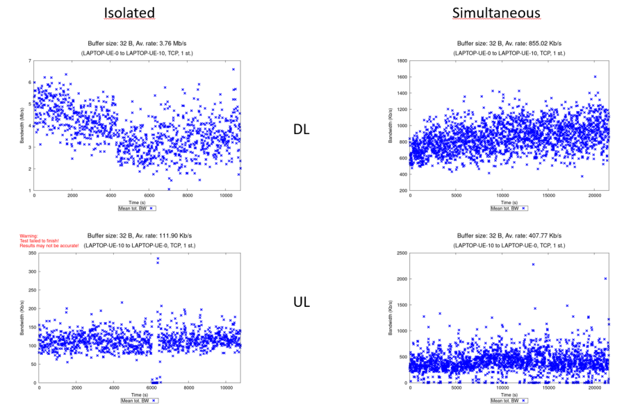
5.1 Throughput Performance Evaluation
In Figures 10, 11, 12, 13, and 14, the isolated and simultaneous analyses of the performance are described for both uplink and downlink.
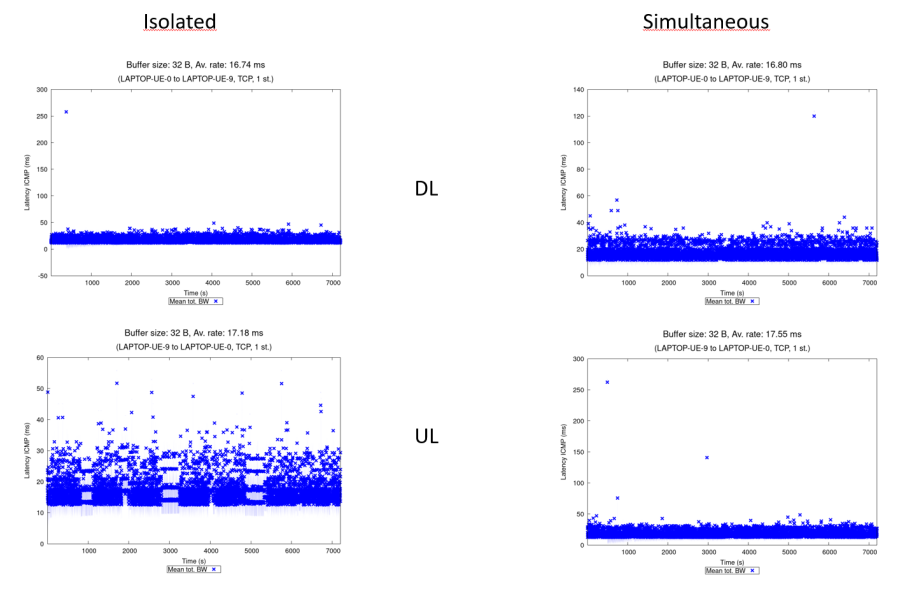
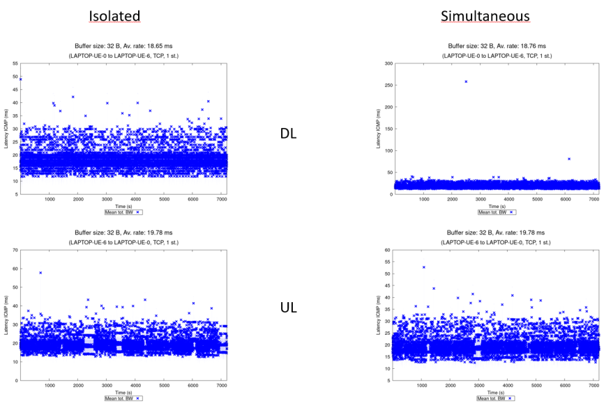
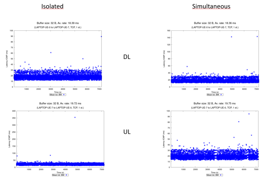
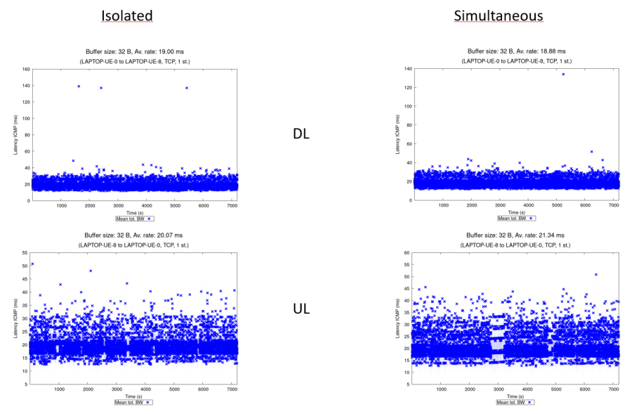
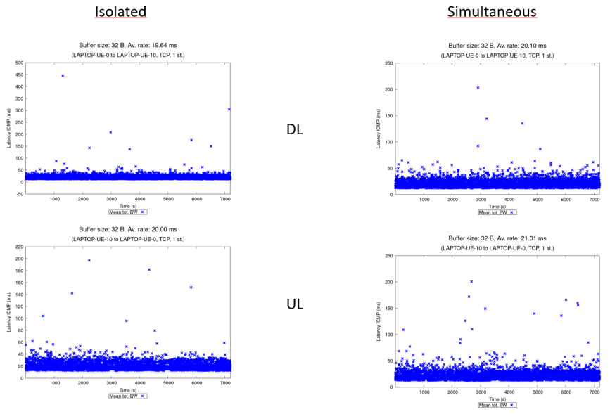
5.2 ICMP Performance Evaluation
Here, the isolated and simultaneous analysis was done based on the ICMP protocol that measures the round-trip time transmission of the data between the transmitter and the receiver. Similar to the previous case, a specialized script was used to automate this measurement. The results for each of the five points are given in Figure 15, 16, 17, 18, and Figure 19.
5.3 Performance Evaluation of the Application
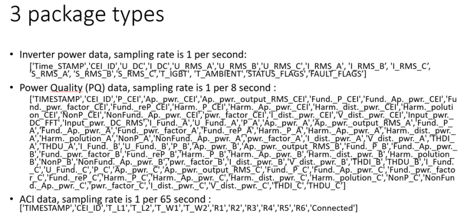
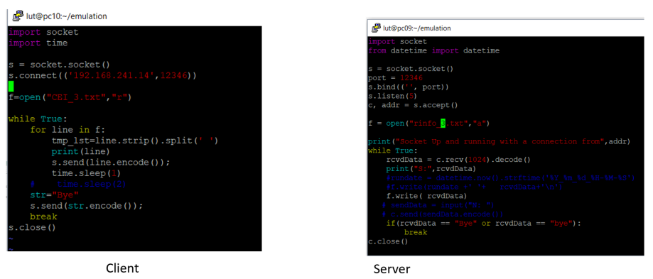
As described above, the application is based on the telemetry transmission of data gathered in each IED installed in each microgrid element. These devices transmit over TCP and UDP 111TCP and UDP are the transport layer elements used by the standard IEC-61850.-relevant information using different sample times between 1 sample per second and 1 sample every 65 s. The messages transmitted to the database are described in Figure 20.
The application transmission sequence was emulated with a TCP client-server application. These scripts enable to configure customized sample times for each scenario. A similar script was used to evaluate UDP. The scripts are illustrated in Figure 21.
In this specific analysis there are different performance outputs. The first one is related to a simultaneous analysis of the message transmission from each inverter to the database using only TCP. As described in Table 4, the network obtained 0% of data lost in all messages.
| TCP - D1 | TCP - D2 | TCP - D3 | |
|---|---|---|---|
| Inverter 01 | 0% | 0% | 0% |
| Inverter 02 | 0% | 0% | 0% |
| Inverter 03 | 0% | 0% | 0% |
Even though the application uses only TCP, based on the flexibility of the Python client-server script, the evaluation was extended to use UDP. This evaluation only focused on the message that is transmitted every second. Thus, in Table 5 it is possible to visualize that TCP is always getting a data message loss of 0%. However, in the scenario with UDP, some marginal error rate is obtained.
| TCP (Simultaneous) - Error Rate (%) | UDP (Simultaneous) - Error Rate (%) | |
|---|---|---|
| Inverter 01 | 0% | 0.2178% |
| Inverter 02 | 0% | 0.21669% |
| Inverter 03 | 0% | 0.2777% |
5.4 Other Results
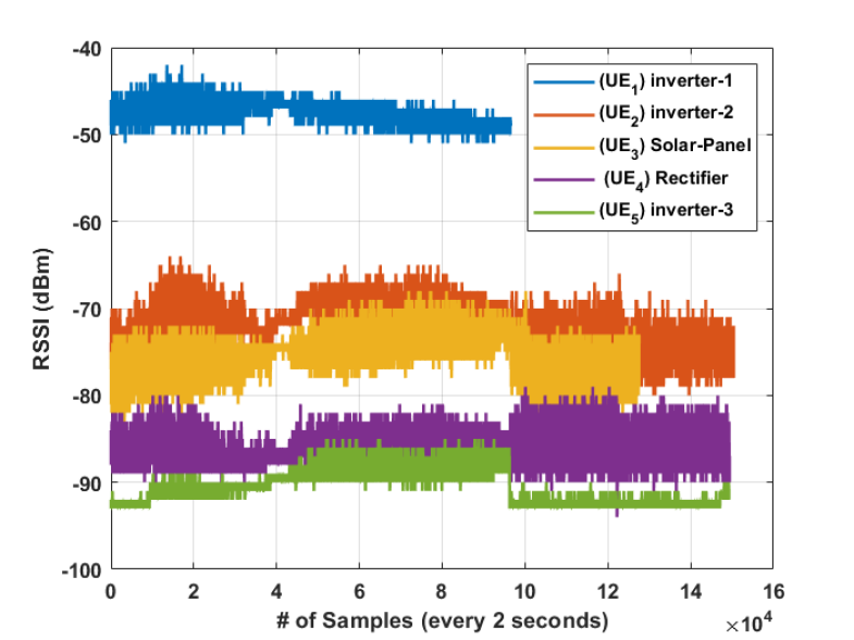
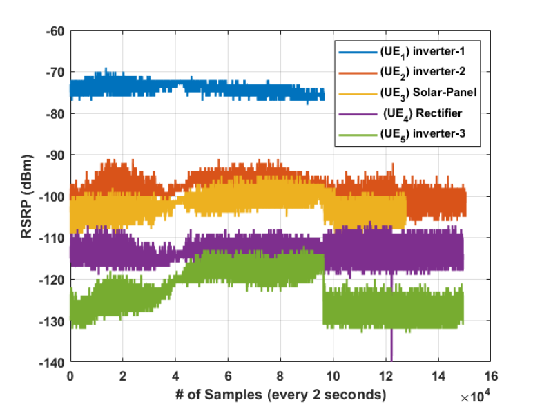
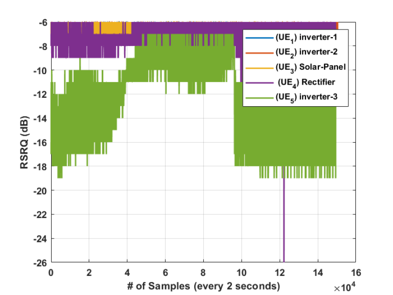
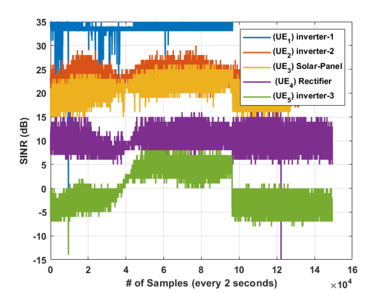
One interesting output of the field measurements is the time-varying evaluation of specific radio metrics, such as RSRP, reference signal reference quality (RSRQ), SINR, and RSSI. These metrics are shown in Figure 22, 23, 24, and 25.
6 Discussion
The main objective of this test bed was to evaluate the performance of a 5G private cellular network. The idea was to examine the readiness of the TCP and UDP stack to transport specific telemetry information, which was gathered from different points in a real microgrid. TCP and UDP were considered, because they are the transport layer protocols defined in the standard IEC-51850. Based on these assumptions, different performance analyses were conducted to evaluate the throughput, latency, and data message integrity in the application.
The throughput was evaluated in both scenarios; the first approach considered a simultaneous transmission, and the other one an isolated transmission for each node. Here, the throughput was between 111.9 Kbps (node in the edge; Inverter 03) and the most robust node that achieved 85 Mbps, considering both scenarios. In general, the simultaneous scenario reduced the throughput in each node. However, in the case of the edge node (Inverter 03), the uplink outperformed the simultaneous setup when compared with the isolated scenario. This performance is probably related to the diversity and self power control of the RAN when multiple nodes are being used.
In the case of latency, the ICMP measurement indicates that in all cases (simultaneous and isolated), including nodes in the edge of the network gave an average latency of 20 ms, which is the maximum latency based on the numerology available in LTE-Advanced specifications.
In the case of the application analysis, the message integrity evaluation indicated that when using TCP, the wireless network achieves 0% of lost. However, this performance was slightly degraded when UDP was used as the transport protocol.
References
- Cisco (2019) Cisco. Substation automation local area network and security cisco validated design, 2019. URL https://www.cisco.com/c/en/us/td/docs/solutions/Verticals/Utilities/SA/2-3-2/CU-2-3-2-DIG/CU-2-3-2-DIG.html.
- Dugan (2010) Jon Dugan. Iperf Tutorial. Columbus: Summer JointTechs, pages 1–4, 2010.
- Eriksson (2017) Linus Eriksson. Performance Evaluation of IEC-61850-90-5 Over a Non-Commercial 4G LTE Network, 2017.
- Kaipia et al. (2012) Tero Kaipia, Pasi Nuutinen, Antti Pinomaa, Andrey Lana, Jarmo Partanen, Juha Lohjala, and Mika Matikainen. Field test environment for lvdc distribution — implementation experiences. In CIRED 2012 Workshop: Integration of Renewables into the Distribution Grid, pages 1–4, 2012. doi: 10.1049/cp.2012.0868.
- Karagiannis et al. (2014) Georgios Karagiannis, Giang T. Pham, A. Dung Nguyen, Geert J. Heijenk, Boudewijn R. Haverkort, and Frans Campfens. Performance of lte for smart grid communications. In Kai Fischbach and Udo R. Krieger, editors, Measurement, Modelling, and Evaluation of Computing Systems and Dependability and Fault Tolerance, pages 225–239, Cham, 2014. Springer International Publishing. ISBN 978-3-319-05359-2.
- Kheaksong et al. (2016) Adisorn Kheaksong, Akara Prayote, and Wilaiporn Lee. Performance evaluation of smart grid communications via network simulation version 3. In 2016 13th International Conference on Electrical Engineering/Electronics, Computer, Telecommunications and Information Technology (ECTI-CON), pages 1–5. IEEE, 2016.
- Lana et al. (2015) A. Lana, A. Pinomaa, P. Nuutinen, T. Kaipia, and J. Partanen. Control and monitoring solution for the lvdc power distribution network research site. In 2015 IEEE First International Conference on DC Microgrids (ICDCM), pages 7–12, 2015.
- (8) MESIDAS. Iec 61850 là gì? URL https://mesidas.com/iec-61850/.
- Musaddiq et al. (2014) Muhammad Musaddiq, Shehryar Khan, Uthman Baroudi, and Bilal Saeed. Performance evaluation of iec 61850 under wireless communication networks. In Proceedings of the 6th International Conference on Management of Emergent Digital EcoSystems, pages 90–94, 2014.
- Nuutinen et al. (2013) Pasi Nuutinen, Tero Kaipia, Pasi Peltoniemi, Andrey Lana, Antti Pinomaa, Pasi Salonen, Jarmo Partanen, Juha Lohjala, and Mika Matikainen. Experiences from use of an lvdc system in public electricity distribution. In 22nd International Conference and Exhibition on Electricity Distribution (CIRED 2013), pages 1–4, 2013. doi: 10.1049/cp.2013.0919.
- Nuutinen et al. (2014) Pasi Nuutinen, Tero Kaipia, Pasi Peltoniemi, Andrey Lana, Antti Pinomaa, Aleksi Mattsson, Pertti Silventoinen, Jarmo Partanen, Juha Lohjala, and Mika Matikainen. Research site for low-voltage direct current distribution in a utility network—structure, functions, and operation. IEEE Transactions on Smart Grid, 5(5):2574–2582, 2014. doi: 10.1109/TSG.2014.2308365.
- Parikh et al. (2010) Palak P Parikh, Mitalkumar G Kanabar, and Tarlochan S Sidhu. Opportunities and challenges of wireless communication technologies for smart grid applications. In IEEE PES General Meeting, pages 1–7. IEEE, 2010.
- Typhoon (a) Typhoon. Iec 61850 goose protocol, a. URL https://www.typhoon-hil.com/documentation/typhoon-hil-software-manual/References/iec_61850_goose_protocol.html.
- Typhoon (b) Typhoon. Iec 61850 mms protocol, b. URL https://www.typhoon-hil.com/documentation/typhoon-hil-software-manual/References/iec_61850_mms_protocol.html.
- Typhoon (c) Typhoon. Iec 61850 sv protocol, c. URL https://www.typhoon-hil.com/documentation/typhoon-hil-software-manual/References/iec_61850_sampled_values_protocol.html.
- Ustun et al. (2020) Taha Selim Ustun, Shaik Mullapathi Farooq, and S. M. Suhail Hussain. Implementing secure routable goose and sv messages based on iec 61850-90-5. IEEE Access, 8:26162–26171, 2020. doi: 10.1109/ACCESS.2020.2971011.