Simultaneous Multi-User MIMO Communications and Multi-Target Tracking with Full Duplex Radios
Abstract
In this paper, we present an Integrated Sensing and Communications (ISAC) system enabled by in-band Full Duplex (FD) radios, where a massive Multiple-Input Multiple-Output (MIMO) base station equipped with hybrid Analog and Digital (A/D) beamformers is communicating with multiple DownLink (DL) users, and simultaneously estimates via the same signaling waveforms the Direction of Arrival (DoA) as well as the range of radar targets randomly distributed within its coverage area. Capitalizing on a recent reduced-complexity FD hybrid A/D beamforming architecture, we devise a joint radar target tracking and DL data transmission protocol. An optimization framework for the joint design of the massive A/D beamformers and the Self-Interference (SI) cancellation unit, with the dual objective of maximizing the radar tracking accuracy and DL communication performance, is presented. Our simulation results at millimeter wave frequencies using 5G NR wideband waveforms, showcase the accuracy of the radar target tracking performance of the proposed system, which simultaneously offers increased sum rate compared with benchmark schemes.
Index Terms:
Full duplex, integrated communications and sensing, radar tracking, millimeter wave, massive MIMO.I Introduction
Integrated Sensing and Communications (ISAC) is emerging as a key feature of the next-generation wireless networks, where sensing and communication signaling operations are unified in a single system to considerably improve spectral and energy efficiencies while reducing both hardware and signaling costs [1, 2, 3, 4, 5]. In addition to its implementation in cellular networks, ISAC systems have recently been considered for a wide variety of applications, e.g., Wi-Fi networks [1], Unmanned Aerial Vehicle (UAV) networks [6], military communications [3], and localization for Vehicular networks (V2X)[7]. As a key enabler for ISAC applications, Full Duplex (FD) massive Multiple-Input Multiple-Output (MIMO) radios have the potential to be employed for the simultaneous DownLink (DL) transmission and UpLink (UL) reception capability within the entire frequency band [8, 9, 10, 11]. FD multi-user massive MIMO systems in conjunction with fifth Generation (5G) millimeter Wave (mmWave) wideband waveforms can provide high-resolution radar target detection and tracking while ensuring high capacity communication links to DL users.
The principal bottleneck of the FD ISAC systems is the Self-Interference (SI) signal induced from the Transmitter (TX) to the Receiver (RX) at the massive MIMO FD Base Station (BS) node due to FD operation. Recently in [11, 12, 13, 9], a combination of propagation domain isolation, analog domain suppression, and digital SI cancellation techniques has been employed to achieve the required SI suppression for the mmWave FD massive MIMO transceivers. Hybrid Analog and Digital (A/D) BeamForming (HBF) is an attractive configuration for FD massive MIMO systems since it utilizes a small number of Radio Frequency (RF) chains connected to large-scale antenna arrays via phase shifters to reduce hardware cost. Appropriate A/D beamforming in the FD HBF system can reduce the impact of SI in the FD RX chains. Thus, a reduced complexity A/D SI cancellation solution can be formulated for FD massive MIMO systems with hybrid beamforming [9, 13].
Recently, single-antenna FD systems employing joint radar communication and sensing were introduced, where both communication and radar waveforms were studied for sensing performance [14, 15]. FD ISAC operations with mmWave massive MIMO systems were proposed in [16, 17]. A multibeam approach with dedicated beams towards both a radar target and a DL user was considered in [16], whereas the authors in [17] provided an ISAC technique detecting the Direction of Arrival (DoA) of two radar targets, while only successfully estimating the range of one target. In [18], we proposed a reduced complexity single-user FD ISAC system with massive MIMO BS operating at mmWave frequencies capable of estimating both the DoA and range of multiple radar targets, while maximizing the DL rate. However, none of the previous works provide an FD ISAC massive MIMO system with radar target tracking protocols across multiple communication slots with simultaneous multi-user DL communication.
In this paper, we present a multi-user FD ISAC system including a protocol for multiple radar target DoA tracking and range estimation across several communication subframes. The considered ISAC system employs an FD massive MIMO BS node communicating with multiple DL users, and utilizes the reflected waveforms to detect and track the radar targets residing within the communication environment. We propose a joint design of the A/D beamformers and a reduced complexity SI cancellation for the FD ISAC system, which target at maximizing the multi-user DL communication rate and the precision of the radar target tracking. We perform an extensive waveform simulation with 5G wideband Orthogonal Frequency Division Multiplexing (OFDM) waveforms at mmWave frequencies, verifying the performance of the proposed multi-user FD ISAC system.
II System and Signal Models
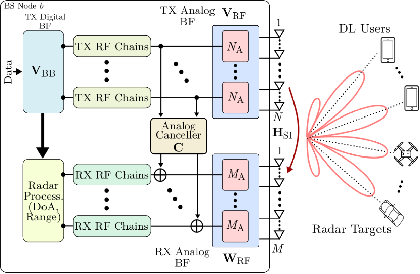
We consider a multi-user FD massive MIMO ISAC system operating at mmWave frequencies, where an FD massive MIMO BS node is communicating with RX user nodes in the DL direction, as depicted in Fig. 1. The DL signals are reflected by the multiple radar targets distributed within the communication environment, which are received and processed at the RX of BS node for radar targets’ parameter estimation enabling integrated sensing and communication.
The FD massive MIMO BS node is comprised of TX and RX antennas, whereas each of the users has RX antennas. To reduce the hardware complexity in massive MIMO BS node, we consider a small number of TX/RX RF chains partially-connected to Uniform Linear Arrays (ULAs) of large number of antenna elements via analog phase shifters following a Hybrid BeamForming (HBF) structure. Therefore, in the BS node, each of the and TX/RX RF chains are connected to ULAs of and antenna elements, respectively. The configurations of the phase shifters are contained in analog beamformers and , respectively. The elements of the TX/RX analog BFs are assumed to have constant magnitude and chosen from predefined beam codebooks, i.e., and . The TX/RX beam codebooks consists of and distinct analog beams, respectively. The RX user nodes are considered to employ fully digital beamforming, since the number of the user antennas is typically much smaller than at the FD massive MIMO BS.
II-A DL and Radar Reflected Signals
We assume a 5G NR subframe-based DL signaling operation for the considered multi-user FD massive MIMO ISAC system. In each subframe, the BS transmits mmWave 5G NR OFDM waveforms to the DL users comprising OFDM symbols with active subcarriers and subcarrier spacing. In addition to the DL communication, these OFDM symbols are reflected by multiple radar targets and received at the BS RX, which is utilized for tracking targets across subframes.
To enable multi-user MIMO communication, each subcarrier of the DL waveform contains parallel data streams for each of the DL users such that . In the BaseBand (BB), the th user’s unit frequency-domain symbol vector at the th subcarrier of th OFDM symbol is precoded using digital beamforming matrix . Furthermore, the precoded signals are processed by the analog BF and the transmitted frequency-domain symbol vector at the antenna elements can be written as
| (1) |
where and . The DL transmission is power limited such that , where represents the maximum transmission power at node .
For the integrated sensing operation, we assume radar targets/scatters randomly distributed within the communication/sensing environment. Each of the targets is associated with a DoD/DoA111It is to be noted that direction of departure and arrival of radar targets are identical since we consider a monostatic radar setup assuming relatively far away targets and small TX-RX array separation. and a range from the BS node corresponding to a respective delay , where represents the speed of light. These radar targets reflect the DL transmitted signal , which is received at the RX of the FD BS node . The radar RX signal comprising reflected and SI signals is expressed as
| (2) |
where and denote the receiver noise vector with covariance and the reflection coefficient of the th radar target, respectively. The propagation delay induces the phase shift across subcarriers [19]. Here, the th element of the ULA response vector with antenna elements and any DoA is expressed as
| (3) |
where and are the signal wavelength and the inter-antenna element distance, respectively. Here, is the Line-of-Sight (LoS) SI channel path between the TX and RX antenna arryas of the BS node , which can be modeled as
| (4) |
where, represents the power normalization constant such that . Here, denotes the distance between th RX and th TX antenna elements at the BS node, which depends on the transmit and receive array geometry [20, eq. (9)].
The received signal at the node RX is processed by the RX analog combiner , which is followed by analog and digital cancellation to suppress the LoS SI signal below the noise floor. In the RX BB of the BS, the frequency-domain radar reflected symbol vector can be expressed as
| (5) |
where and represent the low complexity analog and digital SI cancellers, respectively. After the analog cancellation, the residual SI signal satisfy the RX RF saturation constraint, i.e., , where represents the saturation level of RX RF chains at the BS node . It is to be noted that the low complexity analog canceller suppressing the LoS SI components is designed following the similar structure in [9]. Here, represents the effective LoS SI channel after analog TX/RX beamforming.
For the multi-user DL communication, we assume out of scatterers contribute to the DL channels from the BS node to the users. For each scatter, represents the DoD, while denotes the DoA at the user node. The received DL signal vector at the th user is expressed as
| (6) |
where and represent reflection coefficient of th scatter and the noise floor at RX node with covariance , respectively. Here, represents the DL channel from BS node to th user.
III FD-Enabled Multi-Target Tracking
In this section, we present the proposed FD ISAC DL data transmission and multiple radar target estimation and tracking operation. We utilize the received reflected signals at the BS node RX for estimation and tracking.
III-A Radar Targets/Scatterers Evolution
We assume a 5G NR subframe-based DL communication system, where each radio subframe of duration contains OFDM symbols with subcarriers. The radar targets’ and communication scatters’ parameters are considered to remain constant for one subframe, while the parameters of the successive subframes are temporarily correlated. For any consecutive and th subframes, the evolution of radar DoA components is expressed similar to [21] as
| (7) |
where depends on the velocity of the th radar target and the subframe duration . For simplicity, we assume that all the radar targets are moving with a constant velocity in a circular direction from the BS, hence, . For brevity, the radar targets’ complex-valued reflection coefficients and DL channels complex path gains are assumed to change randomly between consecutive time slots. In this paper, we propose to track only the radar targets’ DoA components for each time subframe. The estimation of all complex path gains and reflection coefficients is left for future investigation.
III-B ISAC Multi-Target Tracking Operation Protocol
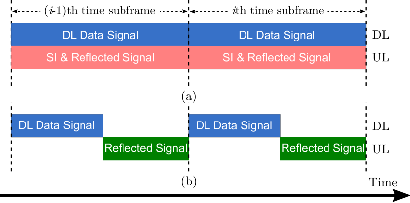
The proposed FD ISAC protocol for DL data transmission and multiple radar target estimation and tracking is illustrated in Fig. 2(a), where the DL channel is dedicated for data transmission to the users while the UL is accessed at the BS node to receive the reflected signals from radar targets simultaneously. The procedures of FD ISAC transmission are described as follows:
-
1.
At any th time subframe, the DL signal reflected by the radar targets is received by the FD BS node enabled by reduced complexity massive MIMO FD analog and digital canceller.
-
2.
Utilizing the received signal after SI suppression, the DoAs of all targets during th time subframe are estimated at the BS node along with their range .
-
3.
During the DL data transmission to users at th time subframe, the estimated DoAs are used to choose appropriate digital beamformer and TX/RX phase shifter configurations and to assure maximized DL rate and satisfy RF saturation level constraint at the BS node .
In Fig. 2(b), a conventional HD ISAC system is illustrated, where, contrary to the FD case, a portion of the subframe is dedicated for DL transmission while the rest is utilized for radar target detection.
III-C Multiple Radar Targets’ DoA Estimation
At the th time subframe, we utilize the received reflected signal to estimate the DoAs of radar targets employing MUltiple SIgnal Classification (MUSIC) algorithm. First, we calculate the sample covariance matrix across all subcarriers and OFDM symbols of th subframe as
| (8) |
Now, we perform the eigenvalue decomposition of the estimated sample covariance matrix as
| (9) |
where are the eigenvalues in the descending order and represents the eigenvector matrix. The matrix is partitioned into signal and noise subspace as , where and contains the noise and signal subspace eigenvectors. Now, we estimate the DoAs of radar targets finding peaks of the MUSIC spectrum formulated as
| (10) |
The peaks of correspond to the estimated DoAs .
III-D Multiple Radar Targets’ Range Estimation
Now, we estimate the range of radar targets at the th subframe. As mentioned before, the range of radar targets corresponds to propagation delay . Here, we obtain the estimated delay at th subframe from which respective range can be achieved. Utilizing the estimated DoAs and the BB transmit signal vector , we formulate a reference signal in the radar target direction as . Now, we formulate a quotient across all RX antennas which includes the propagation delay impact in the direction of as
| (11) |
The quotient is utilized to formulate a likelihood function as , where is the quantized delay parameters. Now, we find the best quantized delay that maximizes the likelihood function norm as follows
| (12) |
Therefore, estimated delay of the th target at th subframe is expressed as and the range is formulated as . The DoA and delay estimation technique is utilized for any subframe to track the radar targets distributed within the communication environment.
IV Proposed Optimization Framework
In this section, we focus on the joint design of the A/D beamformers and SI cancellation matrices at the th subframe to optimize multi-user MIMO communication and multiple radar target tracking performance.
Our proposed FD ISAC optimization framework maximizes the Signal-to-Noise-Ratio (SNR) to the DL users as well as all the radar targets to optimize both tracking and DL communication. Utilizing the estimated DoAs of th subframe , the SNR in all the radar targets’ direction at the th subframe can be expressed as,
| (13) |
where represents the residual SI plus noise covariance. With the objective to maximize DL rate, we devise the sum of DL users’ SNR as
| (14) |
We formulate the optimization problem maximizing both SNR in the Radar target direction and DL users as
| (15) | ||||
We employ an alternating optimization approach to solve this non-convex problem suboptimally. First, using the estimated DoAs at any th subframe, we find for the analog TX/RX BFs that maximizes the signal power toward all radar direction while minimizing the SI channel impact at the RX of BS node . Utilizing the analog BFs, we follow a similar procedure as in [18] to find the taps analog canceller. Finally, we design the multi-user digital precoder using block diagonalization such that it maximizes the SNR of the DL users while minimizing the inter-user interference and suppressing the residual SI at node . The proposed solution for (IV) is summarized in Algorithm 1.
| Parameter | Value |
|---|---|
| Carrier Frequency | GHz |
| Bandwidth | MHz |
| Subframe Duration, | ms |
| OFDM Symbols, | |
| Data Subcarriers, | |
| Subcarrier Spacing, | KHz |
| Parameter | Value |
|---|---|
| Transmit Power | : dBm |
| RX Noise Floor | dBm |
| ADC Bits | bits |
| PAPR | dB |
| Dynamic Range | dB |
| RF Saturation | dBm |
V Numerical Results
In this section, we present the numerical evaluation of the proposed FD massive MIMO multi-user communication and multi-target tracking system through extensive waveform simulation.
V-A Simulation Parameters
Following the FD massive MIMO architecture in Fig. 1, we consider a FD massive MIMO BS node with TX/RX RF chains. Since the BS node employs a partially-connected beamforming structure, each TX/RX RF chain is connected to a ULA of antenna elements via phase shifters. Both TX/RX phase shifter configurations (analog beams) are chosen from -bit Discrete Fourier Transform (DFT) codebooks. The multi-user MIMO communication is realized by users, each with RX antennas. We consider a mmWave communication of GHz frequency with 5G NR OFDM waveforms of MHz BandWidth (BW). Additional 5G NR waveform and system-level parameters are provided in Table. I. The DL channels from BS to the user are assumed to be clustered mmWave channels with dB pathloss. The LoS SI channel is simulated as (4) with mm TX-RX antenna array separation. The RX noise floors at all nodes are considered dBm, which results in dBm of RF saturation level at node for effective dynamic range of dB considering -bit ADCs.
Within the sensing/communication environment, radar targets/scatters are considered out of which contributes to the DL channel. Each target is associated with a DoA and a maximum range of m. We have simulated radio subframes in each simulation run to evaluate the radar target estimation performance.
V-B Multiple Radar Target Sensing Performance
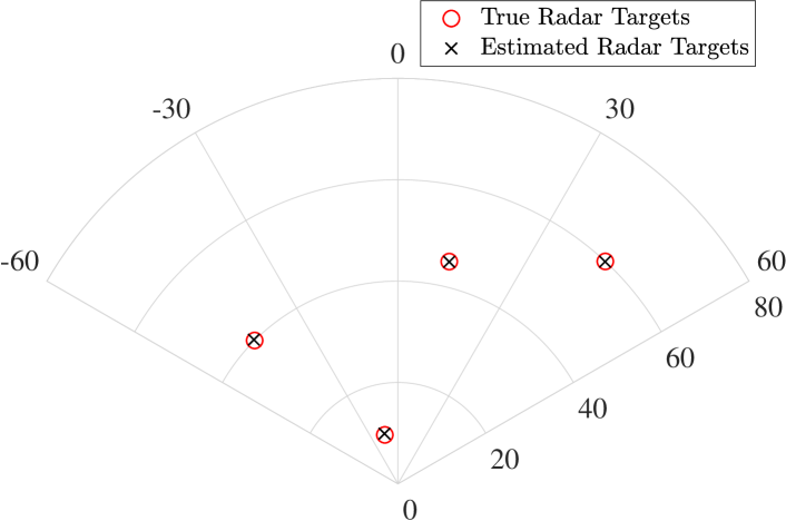
In Fig. 3, we have illustrated the sensing performance of the proposed multi-user FD ISAC system with a massive MIMO node transmitting DL signal with a transmit power of dBm. The estimated DoA and range of each radar target are depicted in the figure. It is evident that the proposed FD ISAC approach successfully estimates the DoA and range of all the radar targets. The precise radar targets’ DoA and range detection performance are due to the proposed target delay estimation associated with the high-resolution MUSIC approach.
V-C Multi-Target Tracking Performance
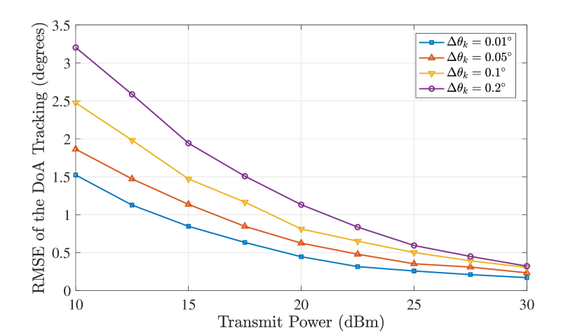
In Fig. 4, we have plotted the Root Mean Square Error (RMSE) of the DoA tracking in degrees for all the radar targets across 5G NR radio subframes with different DoA evolution between consecutive subframes. For a range of m, an angle evolution of corresponds to a velocity of km/h for radar targets. Therefore, the proposed FD ISAC approach is capable of tracking multiple radar targets moving at very high speed. For a moderate transmit power of dBm, the proposed approach provides less than RMSE for most of the DoA evolution cases. However, the RMSE of DoA tracking for all different cases is around for dBm transmit power exhibiting precise target tracking performance.
V-D Multi-user DL Data Rate
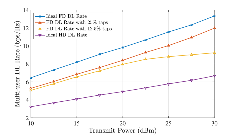
The multi-user DL rate performance of the proposed FD ISAC system is depicted in Fig. 5 for different transmit powers, where the massive MIMO node is communicating with DL users. The proposed FD ISAC approach provides the DL rate within bps/Hz of the ideal FD rate up to dBm transmit power. However, with the increased impact of SI at high transmit powers, the FD ISAC system with () SI cancellation taps exhibits rate reduction compared to the ideal FD case. In contrast, the proposed approach with taps provides comparable performance for all different transmit power values. Furthermore, the proposed FD ISAC system offers a superior multi-user DL rate compared to the ideal HD ISAC approach for all transmit power cases.
VI Conclusion
In this paper, we presented a multi-user FD ISAC framework with an FD massive MIMO node simultaneously transmitting towards multiple DL users and estimating DoA as well as range of radar targets utilizing the reflected DL waveforms. We designed a radar target tracking and DL transmission protocol across multiple communication subframes. Utilizing a limited complexity analog SI cancellation for FD massive MIMO system, we presented a joint design of the A/D beamformer and analog SI cancellation that maximizes both radar target tracking and multi-user DL rate performance. Our performance results considering a mmWave channel model exhibited the high precision DoA and rage estimation of multiple radar targets while providing maximized multi-user DL rate.
Acknowledgments
This work was partially funded by the National Science Foundation CAREER award #1620902.
References
- [1] F. Liu, Y. Cui, C. Masouros, J. Xu, T. X. Han, Y. C. Eldar, and S. Buzzi, “Integrated sensing and communications: Towards dual-functional wireless networks for 6G and beyond,” IEEE J. Sel. Areas Commun., 2022.
- [2] I. Alamzadeh et al., “A reconfigurable intelligent surface with integrated sensing capability,” Scientific Reports, vol. 11, no. 20737, pp. 1–10, Oct. 2021.
- [3] F. Liu, C. Masouros, A. P. Petropulu, H. Griffiths, and L. Hanzo, “Joint radar and communication design: Applications, state-of-the-art, and the road ahead,” IEEE Trans. Commun., vol. 68, no. 6, pp. 3834–3862, Feb. 2020.
- [4] G. C. Alexandropoulos et al., “Hybrid reconfigurable intelligent metasurfaces: Enabling simultaneous tunable reflections and sensing for 6G wireless communications,” [online] https://arxiv.org/abs/2104.04690, 2021.
- [5] K. V. Mishra, M. B. Shankar, V. Koivunen, B. Ottersten, and S. A. Vorobyov, “Toward millimeter-wave joint radar communications: A signal processing perspective,” IEEE Signal Process. Mag., vol. 36, no. 5, pp. 100–114, Sep. 2019.
- [6] X. Wang, Z. Fei, J. A. Zhang, J. Huang, and J. Yuan, “Constrained utility maximization in dual-functional radar-communication multi-UAV networks,” IEEE Trans. Commun., vol. 69, no. 4, pp. 2660–2672, Dec. 2020.
- [7] H. Wymeersch, G. Seco-Granados, G. Destino, D. Dardari, and F. Tufvesson, “5G mmWave positioning for vehicular networks,” IEEE Wireless Commun., vol. 24, no. 6, pp. 80–86, Dec. 2017.
- [8] M. A. Islam et al., “A unified beamforming and A/D self-interference cancellation design for full duplex MIMO radios,” in Proc. IEEE PIMRC, Istanbul, Turkey, Sep. 2019.
- [9] G. C. Alexandropoulos et al., “Full duplex hybrid A/D beamforming with reduced complexity multi-tap analog cancellation,” in Proc. IEEE SPAWC, Atlanta, USA, May 2020.
- [10] M. A. Islam et al., “Simultaneous data communication and channel estimation in multi-user full duplex MIMO systems,” in Proc. IEEE ASILOMAR, Pacific Grove, USA, Nov. 2020.
- [11] A. Sabharwal, P. Schniter, D. Guo, D. W. Bliss, S. Rangarajan, and R. Wichman, “In-band full-duplex wireless: Challenges and opportunities,” IEEE J. Sel. Areas Commun., vol. 32, no. 9, pp. 1637–1652, Sep. 2014.
- [12] M. A. Islam et al., “Direction-assisted beam management in full duplex millimeter wave massive MIMO systems,” in Proc. IEEE GLOBECOM, Madrid, Spain, Dec. 2021.
- [13] I. P. Roberts et al., “Equipping millimeter-wave full-duplex with analog self-interference cancellation,” in Proc. IEEE ICC, Ireland, Jun. 2020.
- [14] C. B. Barneto et al., “Full-duplex OFDM radar with LTE and 5G NR waveforms: Challenges, solutions, and measurements,” IEEE Trans. Microw. Theory Techn., vol. 67, no. 10, pp. 4042–4054, Aug. 2019.
- [15] S. D. Liyanaarachchi et al., “Optimized waveforms for 5G–6G communication with sensing: Theory, simulations and experiments,” IEEE Trans. Wireless Commun., Jun. 2021.
- [16] C. B. Barneto, S. D. Liyanaarachchi, T. Riihonen, M. Heino, L. Anttila, and M. Valkama, “Beamforming and waveform optimization for OFDM-based joint communications and sensing at mm-waves,” in Proc. IEEE ASILOMAR, Pacific Grove, USA, Nov. 2020, pp. 895–899.
- [17] S. D. Liyanaarachchi et al., “Joint multi-user communication and MIMO radar through full-duplex hybrid beamforming,” in IEEE Int. Symp. Joint Commun. & Sensing (JC&S), Feb. 2021, pp. 1–5.
- [18] M. A. Islam et al., “Integrated sensing and communication with millimeter wave full duplex hybrid beamforming,” in Proc. IEEE ICC, Seoul, South Korea, May. 2022.
- [19] M. Braun, C. Sturm, and F. K. Jondral, “Maximum likelihood speed and distance estimation for OFDM radar,” in IEEE Radar Conf., May 2010, pp. 256–261.
- [20] K. Satyanarayana et al., “Hybrid beamforming design for full-duplex millimeter wave communication,” IEEE Trans. Veh. Technol., vol. 68, no. 2, pp. 1394–1404, Dec. 2018.
- [21] V. Va et al., “Beam tracking for mobile millimeter wave communication systems,” in Proc. IEEE GlobalSIP, Dec. 2016, pp. 743–747.