Highly anisotropic geometrical Hall effect via f-d exchange fields
in doped pyrochlore molybdates
Abstract
When a conduction electron couples with a non-coplanar localized magnetic moment, the real-space Berry curvature is exerted to cause the geometrical Hall effect, which is not simply proportional to the magnetization. So far, it has been identified in the case mostly where the non-coplanar magnetic order is present on the sublattice of conduction electrons. Here, we demonstrate that the geometrical Hall effect shows up even without long-range magnetic order of conduction electrons, as induced by non-coplanar exchange fields from the localized magnetic moments, in hole-doped phyrochlore molybdates. We find that the geometrical Hall effect is markedly anisotropic with respect to the applied magnetic field direction, which is in good accordance with the field-dependent magnitude and sign change of the real-space scalar spin chirality of local Tb moments. These results may facilitate the understanding of emergent electromagnetic responses induced by the Kondo-like coupling between conduction electrons and local spins in a broad material class.
Non-collinear or non-coplanar complex magnetic structures in solids are proven to play a fundamentally important role in their spin-related quantum transport and multiferroic properties Tokura2014 ; Nagaosa2013 .
A representative example is the scalar spin chirality (SSC), which is defined by for three neighboring-site spins , and .
As a conduction electron moves over a non-coplanar spin texture with finite SSC, it is endowed with the non-trivial quantum phase (Berry phase) and hence experiences the emergent magnetic field, which can be far beyond a real magnetic field Ye1999 ; Taguchi2001 ; Nagaosa2010 .
One of the most common outcomes of SSC is the unconventional Hall effect, termed geometrical Hall effect (GHE) Nagaosa2010 .
In the case where the mean free path is sufficiently longer than the magnetic period, both anomalous Hall effect (AHE) and GHE are appropriately captured by the momentum space picture where the anti-crossing points (e.g. Weyl nodes) are associated with the Berry curvature due to the spin-orbit coupling (Karplus-Luttinger intrinsic mechanism) and the SSC Ohgushi1999 ; 2003ScienceFang .
In contrast, as the magnetic period is longer than the mean free path, electrons hop around the spin triad in the real space and feel the emergent field , where is the normal vector to the spin triad plane and is the area of spin triad, as exemplified by the magnetic skyrmion lattice 2009PRLNeubauer ; Kanazawai2011 .
Among a variety of non-coplanar magnets, pyrochlore molybdates Mo2O7 ( being a trivalent rare-earth or Y ion) offer an ideal platform to study the correlation between charge transport and non-coplanar magnetism, because of a variety of magnetic/electronic phases 2000PRLKatsufuji ; 2009PRLIguchi ; 2010RMPGardner .
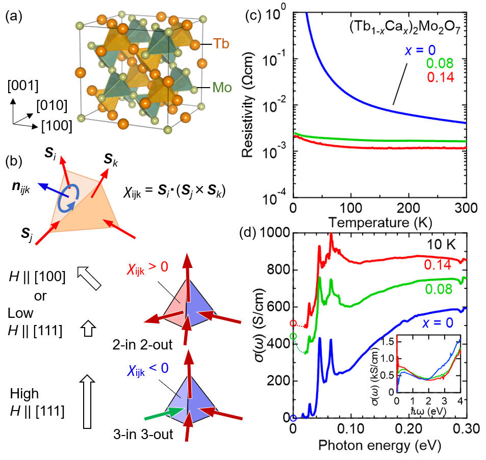
The pyrochlore lattice consists of corner-linked tetrahedra with ions and Mo ions, each of which is displaced by half a unit cell (Fig. 1(a)).
The most well investigated is Nd2Mo2O7 with the possible largest-size ion and hence with relatively small electron correlation.
It is metallic in the whole temperature range and undergoes the ferromagnetic transition at 90 K, presumably due to the double-exchange-like mechanism of Mo- electrons 1989SSCAli .
Additionally, the Nd- magnetic moments, which host Ising anisotropy along the local [111] direction, begin to freeze below around 40 K. Therefore, the Mo spins are slightly tilted ( 5-10∘) via the - magnetic interaction at low temperatures, resulting in the Mo spins with finite SSC (Fig. 1(b)) Taguchi2001 .
Because of such anisotropy for - moments, various configurations are realized under the external magnetic field 1997PRLHarris ; 2001ScienceBramwell .
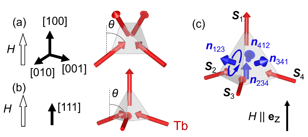
For instance, as the field is applied along [100] direction, two of four magnetic moments point out of the tetrahedron, while the other two inwards, termed the 2-in 2-out configuration.
On the other hand, the field along [111] favors the 3-in 1-out state, as displayed in the bottom panel in Fig. 1(b).
The anisotropy of Hall response in Nd2Mo2O7 is understood in terms of the 2-in 2-out or 3-in 1-out like habit of the Mo- spins transmitted from the corresponding change of Nd- configuration Taguchi2003 .
Such a case where the Mo- ferromagnetic orders are slightly modulated by the - moments is termed the strong coupling, which has been extensively studied so far Taguchi2001 ; 2021PRBHirschberger .
On the other hand, little is known for the weak coupling regime, where the Mo conduction electrons exhibit no spontaneous long-range orders but are moderately influenced by the exchange fields from the - moment configuration Tatara2002 .
Previously, GHE in the weak-coupling regime was studied for the (Tb1-xCdx)2Mo2O7 polycrystals Ueda2012 .
It is demonstrated that the Hall response systematically changes as a function of the “density” of SSC in the real space tuned by the doping level of magnetic Tb moments, in accord with the theoretical prediction Tatara2002 .
However, the exchange-field induced GHE should be dominated by the - moment configuration; for instance, SSC is expected to change its sign and magnitude between 2-in 2-out and 3-in 1-out configuration, and further, diminish as the - moments are forced to align in a collinear manner.
Thus, to obtain a deeper insight into GHE, the field-directional study on the single crystals is required.
In this study, we investigate the magnetotransport properties of (Tb1-xCax)2Mo2O7 single crystals to see the role of the real-space scalar spin chirality in the Hall effect.
We successfully synthesize high-quality samples by using the state-of-the-art floating zone furnace equipped with high-power lasers and measure the transport and magnetization at high magnetic fields up to 31 T, which allows us to access a wide range of Tb magnetic states from non-coplanar spin textures to fully spin-aligned state.
We observe the large anisotropy of geometrical Hall effect between [100] and [111] field directions in the intermediate field range, which gradually diminishes at high fields.
It can be reasonably explained in terms of the magnitude and sign change of the scalar spin chirality of localized Tb moments that impose the f-d exchange field on the conductive Mo sublattice.
Results
Band filling control.
Figure 1(c) shows the temperature dependence of resistivity for several compositions. The resistivity of rapidly increases as the temperature decreases. Above , the resistivity significantly decreases down to the order of . The weak temperature dependence for higher doping reminds us of the high pressure effect on Nd2Mo2O7, which yields the anomalously diffusive metallic state presumably as a result of the strong competition between an antiferromagnetic (spin glass) insulator and ferromagnetic metal states 2009PRLIguchi .
The optical conductivity spectra at 10 K for several is displayed in Fig. 1(d).
The optical conductivity for gradually decreases below 0.2 eV, forming a clear charge gap of 0.05 eV.
The observed magnitude of the charge gap is slightly different from the previous one Kezsmarki2006 , possibly due to the oxygen non-stoichiometry depending on the crystal-growth condition.
With increasing , the optical conductivity gradually increases below 1.5 eV (see the inset of Figure 1(d)) accompanied by the closing of the charge gap, in good accordance with the dc conductivity.
The absence of the clear Drude peak confirms the diffusive metal state at and 0.14.
It is to be noted that the sharp peaks below 0.1 eV are infrared-active phonon modes allowed for cubic pyrochlore lattice 1983JRSVandenborre ; Taniguchi2004 ; Ueda2019 , indicative of a good crystal quality even for the doped metallic samples.
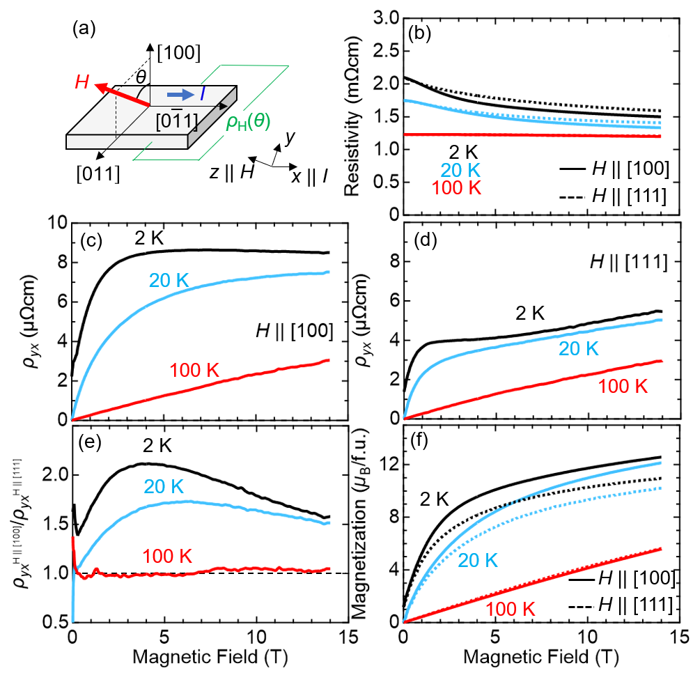
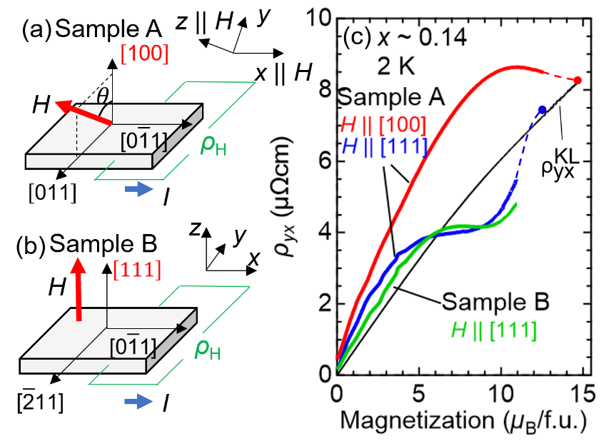
Anisotropic magnetotransport properties. In the following, we focus on the magnetotransport properties of the barely metallic crystal. Figure 2(b) shows the magnetic field dependence of resistivity at several temperatures for and [100]. The resistivity is almost independent of magnetic field at 100 K. Below 20 K, the resistivity gradually decreases with increasing field, likely due to the suppression of spin glass or antiferromagnetic spin fluctuation. Figures 2(c) and (d) show the Hall resistivity for and , respectively. at 100 K is nearly proportional to the magnetic field with little difference between for and . However, the anisotropy becomes evident at low temperatures. At 2 K, as the field increases, for abruptly increases, reaches a maximum value of cm at around 8 T, and then slightly decreases. On the other hand, for shows a hump at around 2 T and gradually increases as the field is further increased. As can be seen in Fig. 2(e), the anisotropy ratio of between and at 2 K exceeds 2 in the intermediate field region, and gradually decreases as the field increases. Figure 2(f) shows the magnetization curves for and . At 100 K, the magnetization shows H-linear dependence and no anisotropy is ovserved as in . With lowering temperature, the magnetization for becomes larger than that for . Such an anisotropy can be attributed to the different magnetic configuration of Tb moments. Since each Tb moment shows single-ion anisotropy along the local orientation, the sufficiently large, but not too large, magnetic field along [100] ([111]) favors 2-in 2-out (3-in 1-out) state (see Fig. 1(b)). In fact, the expected value of 2-in 2-out state is larger than that of 3-in 1-out state by /f.u.. Such a difference of Tb magnetic configuration can give rise to the salient anisotropy of Hall effect.
High magnetic field measurement.
In order to elucidate the origin of Hall effect, we employ the higher magnetic field measurement which allows us to fully control the Tb-moment configurations.
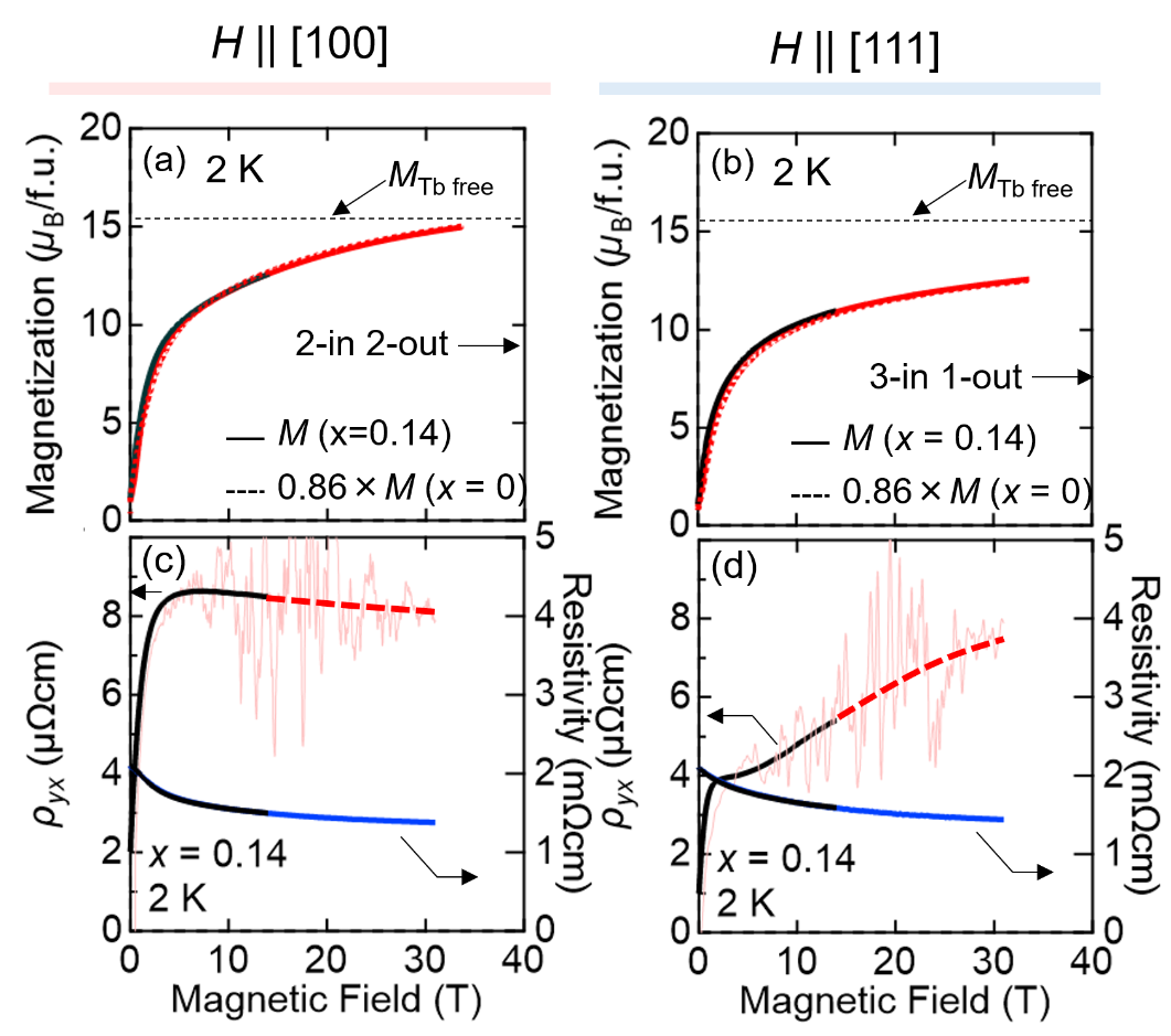
Figure 3(a) (3(b)) shows the magnetic field dependence of magnetization up to above 34 T at 2 K for ([111]).
The magnetization measured by the pulse magnet (red solid curve) perfectly overlaps with the one measured by the dc magnet (black curve).
Remarkably, the magnetization for monotonically increases, exceeds the expected value for the 2-in 2-out state (/f.u.) at 4 T, and nearly reaches 15.5/f.u. at 34 T which is expected for fully-polarized Tb- moments, likely stemming from the competition between the magnetic anisotropy and Zeeman effect.
Thus we can examine the magnetotransport properties for both collinear and non-collinear magnetic states on one sample.
We also plot the magnetization for in Figs. 3(a) and 3(b).
To compare with that for , we renormalize it by the density of Tb moments, namely multiply it by . Notably, the renormalized curve for falls onto the same curve for above 10 T, indicating that the Mo contribution to the whole magnetization is almost negligible not only for the spin-glass insulating crystal but for the carrier-doped metallic one, in stark contrast to the Mo-spin ferromagnetic Nd2Mo2O7 Taguchi2001 .
Figures 3(c) and 3(d) show the magnetic field dependence of resistivity and Hall resistivity for and , respectively.
The resistivity gradually decreases as the field increases up to 31 T for both field directions, as observed in the measurement in the dc magnet.
The Hall resistivity data measured by the pulse magnet seem somewhat noisy, because of the small Hall signals compared to the longitudinal resistivity.
Nevertheless, the overall field dependence and amplitude are reconciled with the dc data, and moreover the signal appears reliable again near the maximum field, since the data can be integrated during the relatively long time at high fields in the field pulse shape.
As the field approaches to 31 T, for gradually decreases down to cm, while that for explicitly increases up to . Apparently, the anisotropy of disappears at high magnetic fields.
Discussion
In general, the Hall resistivity is expressed as
| (1) |
where is the ordinary Hall coefficient, the anomalous Hall coefficient with the scaling factor in case of diffusive metal Miyasato2007 , and the geometrical contribution. According to the previous study on Cd-doped Y2Mo2O7, the ordinary Hall effect is quite small (less than at 14 T). Therefore, we neglect here the ordinary contribution for simplicity. To extract the geometrical contribution, we plot as a function of magnetization in Fig. 4(a). The red and blue solid lines denote experimental data measured in dc magnetic field, red and blue circles are the data at the highest field 31 T, and red and blue dashed lines indicate the noise-smoothed connections between these two experimental data. Since the magnetization for is almost saturated at 31 T (Fig. 3(a)), we can assume that the geometrical contribution is zero at 31 T. The black line in Fig. 4(a) indicates the Karplus-Luttinger type anomalous Hall resistivity, , where in the carrier hopping regime, as confirmed in Supplementary Figure 2Miyasato2007 . As can be seen, for is larger than in the whole magnetization regime. Remarkably, for , shows non-monotonic magnetization dependence as opposed to . Especially, crosses at /f.u., and eventually merges to at the largest magnetization.
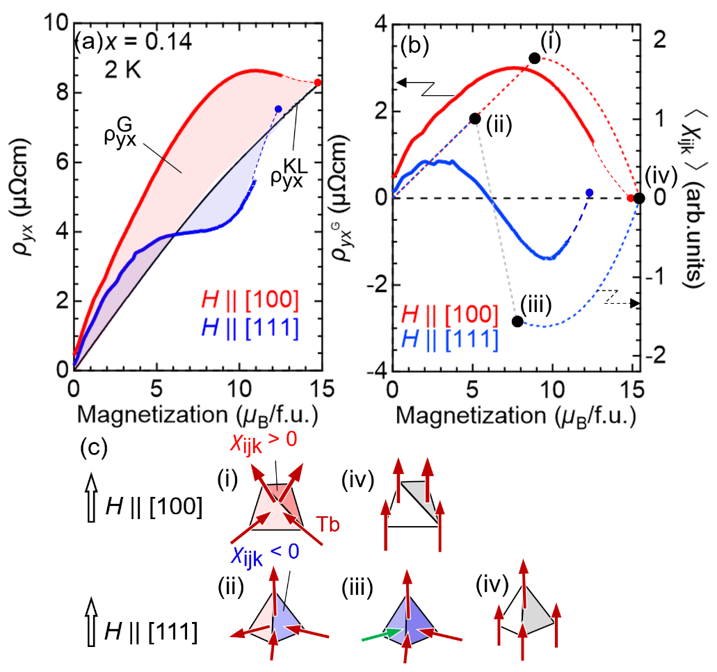
Figure 4(b) displays the extracted geometrical contribution, , as a function of magnetization.
As the magnetization increases, for gradually increases, reaches maximum at /f.u., and eventually decreases towards zero at the full moment of /f.u.
We speculate that the envelope-shaped magnetization dependence, which is also observed in several materials Ye1999 ; 2021PNASKolincio , reflects the modulation of Tb magnetic states.
Both Tb and Mo magnetic moments are disordered at zero magnetic field.
As the field increases, the large Tb moments are getting aligned due to the gain of Zeeman energy under the influence of the [111] Ising anisotropy, and eventually form 2-in 2-out like configuration at /f.u. (see panel (i) in Fig. 4(c)).
With further increasing field, the Zeeman energy gradually overcomes the magnetic anisotropy energy, and finally the Tb moments are fully aligned collinearly, as shown in panel (iv) in Fig. 4(c).
Here we simulate the average of SSC in a single tetrahedron having four triangle planes, as shown in Fig. 1(b) (see Supplementary Note 3 for more detail).
Assuming that all Tb moments simply approach to the field direction with increasing field, we can calculate the angle between Tb moments and the external field from the magnetization value, and hence obtain .
Starting from the perfect 2-in 2-out state (panel (i)), monotonically decreases towards zero (panel (iv)) as the magnetization is increased.
This is intuitively understandable since the solid angle subtended by Tb moments becomes smaller as the applied field is increased.
On the other hand, for shows unique magnetization dependence.
It is somewhat similar to that for below 2 /f.u., but decreases towards the negative value as the magnetization is further increased.
It takes minimum (negative maximum) at /f.u. and then approaches zero at the large magnetization value. To understand this behavior, we consider the magnetic configuration and .
According to the neutron diffraction experiments Ehlers2010 , Tb-Tb interaction in Tb2Mo2O7 is ferromagnetic, and hence favors the 2-in 2-out magnetic structure at weak magnetic fields, similar to canonical spin ice systems Dy2Ti2O7 and Ho2Ti2O7 1997PRLHarris ; Sakakibara2003 , and spin-ice like ordered semimetal Pr2Ir2O7 2015PRBMacLaughlin ; 2022PRBUeda .
At the intermediate field applied along [111], the apical spins, whose easy axes are along the field direction, are fixed while other three spins obey the ice rule, forming the so-called kagomé ice state (see panel (ii) in Fig. 4(c)).
Moreover, moments with the strong Ising character undergo the liquid-gas type magnetic transition from the kagomé ice state to 3-in 1-out state (panel (iii) in Fig. 4(c)) at higher fields.
We speculate that the crossover between these magnetic states occurs in the present system as well, leading to the remarkable sign change of and hence of , as shown in Fig. 4(b).
In fact, the sign of changes at /f.u., consistent with the experimental observation of the sign change of GHE.
While the magnetization value exceeds that for the 3-in 1-out state, we anticipate that the 3-in Tb moments in the 3-in 1-out state are forcedly aligned toward the collinear state.
slightly decreases and forms a broad dip centered at /f.u., and quickly increases towards zero at 15.5/f.u..
Despite such a simplified simulation of , the overall magnetization dependence of can be well explained.
The present experimental data clearly indicate that the GHE is controlled by the exchange fields from the configuration of the local Tb moments in the weak coupling regime.
In conclusion, we observe the geometrical Hall effects in the pyrochlore type (Tb1-xCax)2Mo2O7 single crystal, whose conduction electrons are interacting with local magnetic moments in the weak coupling region, and thus represent the ideal platform to study the correlation between electronic transport and non-collinear magnetism.
The highly field-anisotropic geometrical Hall effect can be well explained by the real-space scalar spin chirality arising from the non-coplanar Tb magnetic configurations.
We clearly demonstrate that there is one-to-one correspondence between the geometrical Hall effect and scalar spin chirality, both of which vary for several magnetic states, e.g. 2-in 2-out, 3-in 1-out, and fully-aligned collinear states.
Methods
Single crystal growth.
Single crystals (Tb1-xCax)2Mo2O7 were synthesized by using the state-of-the-art floating zone furnace equipped with high-power lasers Kaneko2020 . Firstly, Tb2O3, CaCO3, and MoO2 were mixed in stoichiometric ratio, pressed into pellet, and baked at 1000 for 12 hours under argon atmosphere. After cooling to the room temperature, it was well grounded, and pressed into rods, and baked again at 1400 for 18 hours under argon atmosphere. The sintered rod was heated at 1880 under an argon atmosphere of 0.99 MPa in the laser floating zone furnace. The single crystals were well characterized by x-ray powder diffraction and energy dispersive x-ray to check the lattice structure and composition. The crystal orientation was determined by back-Laue pattern.
Transport and magnetization measurements.
The transport properties and magnetization up to 14 T were measured by using dc magnets in Physical Property Measurement System (PPMS), Quantum Design.
Higher-field measurements of magnetotransport and magnetization were performed by using non-destructive pulse magnets energized by capacitor banks and a flywheel DC generator installed at International MegaGauss Science Laboratory of Institute for Solid State Physics (ISSP), University of Tokyo.
Resistivity and Hall conductivity were measured by a five-probe method.
Transport measurement setup is shown in Fig. 2(a). The electric current flows along crystalline direction. The magnetic field was rotated around the current direction, so that the transport measurements for different orientations can be performed on the same sample. , which is perpendicular to the sample plane, is along [100] crystalline direction, while is along the [111] and its equivalent direction.
We obtained the Hall resistivity by normalizing the measured Hall signal for divided by .
We confirm that the deduced shows almost the same behavior as another sample with the [111] plane measured under the normal [111] field (see Supplementary Figure 1).
Optical measurement.
Reflectivity spectra for vertical incidence light were measured in the range of 0.008 to 5 eV.
We used Fourier transform spectrometers for infrared region and grating-type ones for visible to ultraviolet region.
Room-temperature spectra measurement up to 40 eV were performed by using synchrotron radiation at UV-SOR, Institute for Molecular Science.
Optical conductivity spectra were obtained by Kramers-Kronig analysis.
As for a lower energy (0.008 eV) region, we used constant reflectivity extrapolation for and Hagen-Rubens relation for .
As for a higher energy (40 eV) region, we assumed where is the reflectivity and
is photon energy.
Supplementary Material
S1. Hall resistivity measurement.
The magnetic anisotropy of Hall effect was investigated by rotating the sample A against the applied magnetic field, so that we can rule out the possibility of sample dependence.
Fig. S1(a) shows the geometry of the sample A.
It was polished into the plate-like shape whose vertical direction is along [100] crystalline axis.
The electric current was flowed along [01] axis, about which the magnetic field was rotated.
The transverse resistivity was measured along [011] axis which is perpendicular to both [100] and [01] axes.
Let us take the magnetic field direction as the -axis and the current direction as the -axis, as depicted in Fig. S1(a). When the field is tilted by off [100] direction, Hall resistivity is expressed as
| (2) |
The first term is the usual Hall effect perpendicular to both magnetic field and current, which should be extracted from the measured value . Considering the symmetry of the setup of Fig. S1(a), we obtain and , while is odd. Therefore, we can extract by averaging and and then dividing by . Fig. S1(c) displays the magnetization dependence of for both [100] and [111] field directions, in which one can clearly see the anisotropy, as discussed in the main text.
To double-check for , we prepare another sample B, whose out-of-plane axis is along [111] crystalline direction while the current direction is the same as that in sample A ([01]). In this geometry, we can obtain for without any calculation, as plotted in Fig. S1(c). Although the chemical composition of sample B () is slightly different from that of sample A (), of sample B is remarkably similar to that of sample A for . Thus, the anisotropy discussed in the main text is ubiquitous for the present system.
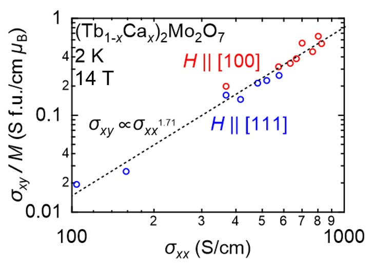
S2. Scaling Law for Hall Conductivity. In the hopping region, the anomalous Hall conductivity is known to follows the empirical scaling relation where is longitudinal conductivity Miyasato2007 . Fig. S2 shows normalized by magnetization as a function of for several different samples at 2 K and 14 T, at which the anomalous Hall contribution is dominant. One can see that holds for a wide range of from 102 S/cm to 103 S/cm. Therefore, we use in eq. (1) in the main text to estimate the Karplus-Luttinger term . However, the -dependence of is not large, and even if there were a slight discrepancy in , the conclusion shown in Fig.4 of the main text would be hardly affected.
S3. Calculation of the scalar spin chirality. Since the Mo magnetization in (Tb1-xCax)2Mo2O7is negligible, as demonstrated in Fig. 2 of the main text, we can speculate the magnetic structure of the Tb tetrahedra from the magnetization and hence calculate the scalar spin chirality .
First we consider the case for . At zero magnetic field, Tb magnetic moments are disordered but host 2-in 2-out (2I2O) like habit because of the ferromagnetic interaction between nearest-neighbor Tb moments. As the magnetic field increases, the number of 2I2O Tb tetrahedra, whose net magnetizations are parallel to the field direction, increases and hence the magnetization reaches the expected value of [/f.u] where [/Tb] (state (i) in Fig. 4(c) of the main text). With increasing field above 2 T, we speculate that the Zeeman energy overcomes the single-ion anisotropy and hence the Tb moments gradually approach the field direction. We define as the angle between the Tb moments and the magnetic field direction (Fig. S3(a)), so that the magnetization is given as . In this way, we estimate the tilt angle of the Tb moment from the measured magnetization to calculate as discussed later.
Magnetization process for is more complex. Similar to spin-ice materials, the magnetization for [111] field direction increases with increasing field towards [/f.u], at which the kagome ice state is realized (the state (ii) in Fig. 4(c) in the main text). In other words, the 2-in 2-out state is preserved up to , resulting in the nearly the same curve as the case for . Above , the crossover occurs from (ii) 2-in 2-out state to (iii) 3-in 1-out state, at which the magnetization becomes [/f.u]. Eventually, as the field increases further, Tb moments deviate from the local axes and get aligned collinearly (the state (iv) in Fig. 4(c) of the main text). Between (iii) and (iv) states, the magnetization is written as where is the angle between Tb moments and the field, as shown in Fig. S3(b).
Making use of the information of Tb magnetic configurations as extracted above, we calculate the spin chirality of the Tb tetrahedron averaged over four Tb sites on the vertices of one tetrahedron. According to the theoretical calculation in the weak coupling region Tatara2002 , the emergent magnetic field acting on the Mo-conducting electrons is given as
| (3) |
where
| (4) |
is the unit vector parallel to the field direction, , , and are the positions of local spins at site ,, and , , , are the distances between each site, is the rapidly decreasing function of , and . Thus we take into account only the nearest neighbor sites 1, 2, 3, and 4 in a single tetrahedron shown in Fig. S3(c)
| (5) |
where is the unit vector defined by right hand screw rule when orbiting the site , , and . The calculated results are plotted in Fig. 4(c) in the main text. We note that the spin chirality is not calculated but just a connecting straight line drawn between and in (the state (ii) and (iii) in Figs. 4(b) and 4(c)), because the detailed magnetic state is not trivial.
The calculated curves of the SSC based on the above simple assumption reasonably reproduce the experimental results of geometrical Hall components.
Data availability. The data that support the findings of this study are available from the corresponding author upon reasonable request.
References
- (1) [*] Electronic address: ueda@ap.t.u-tokyo.ac.jp
- (2)
- (3) [References.]
- (4) Tokura, Y., Seki, S. & Nagaosa, N. Multiferroics of spin origin. Rep. Prog. Phys. 77, 076501 (2014).
- (5) Nagaosa, N. & Tokura, Y. Topological properties and dynamics of magnetic skyrmions. Nat. Nanotechnol. 8, 899-911 (2013)
- (6) Ye, J., Kim, Y. B., Millis, A. J., Shraiman, B. I., Majumdar, P. & Tesanovic, Z. Berry Phase Theory of the Anomalous Hall Effect: Application to Colossal Magnetoresistance Manganites. Phys. Rev. Lett. 83, 3737 (1999).
- (7) Taguchi, Y., Oohara, Y., Yoshizawa, H., Nagaosa, N. & Tokura, Y. Spin Chirality, Berry Phase, and Anomalous Hall Effect in a Frustrated Ferromagnet. Science 291, 2573 (2001).
- (8) Nagaosa, N., Sinova, J., Onoda, S., MacDonald, A. H. & Ong, N. P. Anomalous Hall effect. Rev. Mod. Phys. 82, 1539
- (9) Ohgushi, K., Murakami, S. & Nagaosa, N. Spin anisotropy and quantum Hall effect in the kagomé lattice: Chiral spin state based on a ferromagnet. Phys. Rev. B. 62, R6065(R) (1999).
- (10) Fang, Z., Nagaosa, N., Takahashi, K. S., Asamitsu, A, Mathieu, R., Ogasawara, T., Yamada, H., Kawasaki, M., Tokura, Y. & Terakura, K. The Anomalous Hall Effect and Magnetic Monopoles in Momentum Space. Science 302, 92 (2003).
- (11) Neubauer, A., Pfleiderer, C., Binz, B., Rosch, A., Ritz, R., Niklowitz, P. G., & Bni, P. Topological Hall Effect in the Phase of MnSi. Phys. Rev. Lett. 102, 186602 (2009).
- (12) Kanazawa, N., Onose, Y., Arima T., Okuyama, D., Ohoyama, K., Wakimoto, S., Kakurai, K., Ishiwata, S., & Tokura, Y. Large Topological Hall Effect in a Short-Period Helimagnet MnGe. Phys. Rev. Lett. 106, 156603 (2011).
- (13) Katsufuji, T., Hwang, H. Y. & Cheong, S.-W. Anomalous Magnetotransport Properties of Mo2O7 near the Magnetic Phase Boundary. Phys. Rev. Lett. 84, 1998 (2000).
- (14) Iguchi, S., Hanasaki, N., Kinuhara, M., Takeshita, N., Terakura, C., Taguchi, Y., Takagi, H., & Tokura, Y. Emergence of a Diffusive Metal State with No Magnetic Order near the Mott Transition in Frustrated Pyrochlore-Type Molybdates. Phys. Rev. Lett. 102, 136407 (2009).
- (15) Gardner, J. S., Gingras, M. J. P., & Greedan, J. E., Rev. Mod. Phys. 82, 53 (2010)
- (16) Ali, N., Hill, M. P., Labroo, S. & Greedan, J. E. Magnetic and electrical properties of Mo2O7 pyrochlore compounds. J. Solid State Chem. 83, 178 (1989).
- (17) Harris, M. J., Bramwell, S. T., McMorrow, D. F., Zeiske, T. & Godfrey, K. W. Geometrical Frustration in the Ferromagnetic Pyrochlore Ho2Mo2O7. Phys. Rev. Lett. 79, 2554 (1997)
- (18) Bramwell, S. T. & Gingras, M. J. P. Spin Ice State in Frustrated Magnetic Pyrochlore Materials. Science 294, 1495 (2001).
- (19) Taguchi, Y., Sasaki, T., Awaji, S., Iwasa, Y., Tayama, T., Sakakibara, T., Iguchi, S., Ito, T. & Tokura, Y. Magnetic Field Induced Sign Reversal of the Anomalous Hall Effect in a Pyrochlore Ferromagnet Nd2Mo2O7 : Evidence for a Spin Chirality Mechanism. Phys. Rev. Lett. 90, 257202 (2003).
- (20) Onoda, M., Tatara, G. & Nagaosa N. Anomalous Hall Effect and Skyrmion Number in Real and Momentum Spaces. J. Phys. Soc. Jpn. 73, 2624 (2004).
- (21) Hirschberger, M., Nomura, Y., Mitamura, H., Miyake, A., Koretsune, T, Kaneko, Y., Spitz, L., Taguchi, Y., Matsuo, A., Kindo, K., Arita, R., Tokunaga, M. & Tokura, Y. Geometrical Hall effect and momentum-space Berry curvature from spin-reversed band pairs. Phys. Rev. B 103, L041111 (2021).
- (22) Ueda, K., Iguchi, S., Suzuki, T., Ishiwata, S., Taguchi, Y. & Tokura, Y. Topological Hall Effect in Pyrochlore Lattice with Varying Density of Spin Chirality. Phys. Rev. Lett. 108, 156601 (2012).
- (23) Tatara, G. & Kawamura, H. Chirality-Driven Anomalous Hall Effect in Weak Coupling Regime. J. Phys. Soc. Jpn. 71, pp. 2613-2616 (2002).
- (24) Kézsmarki, I., Hanasaki, N., Watanabe, K., Iguchi, S., Taguchi, Y., Miyasaka, S. & Tokura, Y. Variation of the charge dynamics in bandwidth- and filling-controlled metal-insulator transitions of pyrochlore-type molybdates. Phys. Rev. B 73, 125122 (2006).
- (25) Vandenborre, M. T., Husson, E., Chatry, J. P. & Michel, D. Rare-earth titanates and stannates of pyrochlore structure; vibrational spectra and force fields. J. Raman Spectrosc. 14, 63 (1983).
- (26) Taniguchi, K., Katsufuji, T., Iguchi, S., Taguchi, Y., Takagi, H. & Tokura, Y. Raman study of the metal-insulator transition in pyrochlore Mo oxides. Phys. Rev. Lett. 70, 100401(R) (2004)
- (27) Ueda, K., Kaneko, R., Subedi, A., Minola, M., Kim, B. J., Fujioka, J., Tokura, Y. & Keimer B. Phonon anomalies in pyrochlore iridates studied by Raman spectroscopy. Phys. Rev. B 100, 115157 (2019)
- (28) Iguchi, S., Kumano, Y., Ueda, K., Kumakura, S. & Tokura, Y. Diffusive charge transport with strongly renormalized carrier mass in hole-doped Mott insulators (Y1-xCdx)2Mo2O7 with frustrated pyrochlore lattice. Phys. Rev. B 84, 174416 (2011)
- (29) Miyasato, T., Abe, N., Fujii, T., Asamitsu, A., Onoda, S., Onose, Y., Nagaosa, N. & Tokura, Y. Crossover Behavior of the Anomalous Hall Effect and Anomalous Nernst Effect in Itinerant Ferromagnets. Phys. Rev. Lett. 99, 086602 (2007).
- (30) Kolincio, K. K., Hirschberger, M., Masell, J., Gao, S., Kikkawa, A., Taguchi, Y., Arima, T., Nagaosa, N. & Tokura, Y. Large Hall and Nernst responses from thermally induced spin chirality in a spin-trimer ferromagnet. Proc. Nat. Acad. Sci. 118, (2021).
- (31) Ehlers, G., Greedan, J. E., Stewart, J. R., Rule, K. C., Fouquet, P., Cornelius, A. L., Adriano, C., Pagliuso, P. G. , Qiu, Y. & Gardner, J. S. High-resolution neutron scattering study of Tb2Mo2O7 : A geometrically frustrated spin glass. Phys. Rev. B. 81, 224405 (2010)
- (32) Sakakibara, T., Tayama, T., Hiroi, Z., Matsuhira, K. & Takagi, S. Observation of a Liquid-Gas-Type Transition in the Pyrochlore Spin Ice Compound Dy2Ti2O7 in a Magnetic Field. Phys. Rev. Lett. 90, 207205 (2003).
- (33) MacLaughlin, D. E., Bernal, O. O., Shu, L., Ishikawa, J. J., Matsumoto, Y., Wen, J. J., Mourigal, M., Stock, C., Ehlers, G., Broholm, C. L., Machida, Y., Kimura, K., Nakatsuji, S., Shimura, Y. & Sakakibara, T. Unstable spin-ice order in the stuffed metallic pyrochlore Pr2+xIr2-xO7-δ. Phys. Rev. B 92, 054432 (2015).
- (34) Ueda, K., Ishizuka, H., Kriener, M., Kitou, S., Maryenko, D., Kawamura, M., Arima, T., Kawasaki, M. & Tokura, Y. Experimental signatures of a versatile Weyl semimetal in a pyrochlore iridate with spin-ice-like magnetic orders. Phys. Rev. B 105, L161102 (2022).
- (35) Kaneko, Y. & Tokura, Y. Floating zone furnace equipped with a high power laser of 1 kW composed of five smart beams. J. Cryst. Growth 533, 125435 (2020)
Acknowledgements.
We would like to thank enlightning discussion with Max Hirschberger.
This work was supported by JSPS/MEXT Grant-in-Aid for Scientific Research(s) (grant no. 21K13871) and CREST (Grant no. JPMJCR1874) from JST.
Author contributions
Y.To. conceived and guided the project. H.F. and Y.K. performed single crystal growth.
H.F. measured transport, magnetization, optical conductivity up to 14 T with help from K.U., K.K. and Y.Ta..
H.F., R.K., A.M. and M.T. performed high field measurement of transport and magnetization.
All authors discussed the results and contributed to the manuscript.