Half-metallicity and two-dimensional hole gas at the (001) surface
Abstract
The electronic structure and thermodynamic stability of tetragonal (001) surfaces have been
investigated using density functional theory. In this work, four different structures having different lattice constants with
two possible surface terminations have been studied. We have found that the surface electronic structure and the thermodynamic stability is quite
sensitive with respect to the nature of the surface termination. The terminated surface is found to be energetically
more stable compared to terminated surface in all the cases. Interestingly, we have found evidences of half-metallicity
and spin-polarized two-dimensional hole gas (2DHG) at the one mono-layer thick surface in all the structures.
The effect of the surface thickness have been systematically studied.
It has been demonstrated that the half-metallic 2DHG survives
only in one of the structures for all the thicknesses, incidentally, which is the most thermodynamically stable structure.
Keywords: Tetragonal (001), Half-metallicity, 2DHG
I Introduction
The study of two-dimensional systems like oxide interfaces and the surface analysis of perovskite systems have received wide attention since the discovery of the two dimensional electron gas (2DEG) in the hetero-interface2deg and its counterpart i.e., two dimensional hole gas (2DHG) in the //2dhg . In addition, the 2DHG is also found in interfacesto-interface . These findings open up new windows of opportunities from the point of view of designing novel functional devices. In 2006, R. Pentcheva and W. E. Pickettpickett-hole-polaron reported the presence of magnetic holes in p-type interface of /. Interestingly, the half-metallic 2DHG is found in the interface sto/kto-2dhg .
Following these findings, the search for 2DEG and 2DHG has been extended to other systems, for example, existence of 2DEG has been experimentally found in the surface of kto-2deg when the electrons are confined along the direction. On the other hand, based on density functional theory based first principle calculations, existence of 2DEG has been predicted in the slab structures of the polar perovskites, such as BaBio3-2deg and in sto-111 sto-111a . Apart from these, there have been several other studies on other polar perovskites, for example the stability and structural properties of slabs have been studied in Ref. bto-110 , polar surface structures of , and were studied in Ref. polar-compounds , while the surface properties of rhombohedral has been investigated in Ref. rbfo-0001 . In addition, the rhombohedral thin film is studied experimentally in Ref. rbfo-expt . However, 2DHG has only been found in a limited set of systems as compared to the 2DEG. Recently, it has been reported that 2DHG co-exists with 2DEG in the strained polar perovskite thin film of kto-tf .
Motivated by these studies, in this work, we have investigated the slab structures of tetragonal (TBFO), which is also a polar perovskite. Recently, bulk TBFObulk-paper has been found to host wide range of electronic phases in the presence of ferromagnetic ordering. In the past, TBFO has been fabricated having a wide range of the ratiosbulk-paper . Interestingly, it has been found that certain bulk structures of TBFO can become half-metallic groot in the presence of ferromagnetic ordering of the spins. Furthermore, in the half-metallic phase of the bulk system the charge carriers were found to be of electron type.

Naturally the question arises whether the half-metallic phase also survives on the surface of a TBFO slab structure, and, if it survives, are the charge carriers still electron type or the reduced dimensionality brings in some drastic changes in its nature. To address these questions, we have systematically studied the surface of the slab geometries with increasing thickness (1, 2 and 3 monolayers) for four different structures (I, II, III, and IV) of TBFO having different lattice parameters bulk-paper . Furthermore, the TBFO-slabs have been examined with positive () and negative () surface terminations. The electronic properties of the surface have been found to be drastically influenced by the nature of the termination layer. All the structures have been found to host metallic surface states when the surface is positively terminated. However, when the surface is negatively terminated, the nature of the surface states have been found to be sensitive to the thickness of the slab as well as on the lattice parameters. Out of all the structures, the surface states of the structure II have been found to possesses the highest robustness with respect to the change in the slab thickness. Interestingly, the surface of this structure has been found to be half-metallic similar to its bulk counterpart. Surprisingly, however, the charge carriers become hole type in the slab, in contrast to the bulk structure, indicating the existence of spin-polarized 2DHG at the surface of TBFO slab. It is important to note that, half-metallic ferromagnetism (HMFM) has also been reported in TBFO based hetero-structure systems lsmo/bfo lsmo/bfo-hm 2d-pbo/bfo-hm . Also, existence of 2DEG has been predicted in heterostructurebfo-sto . To the best of our knowledge, possibility of spin-polarized 2DHG in pure TBFO slab is being reported for the first time in this work.
The paper is organized as follows: Computational and structural details are provided in Sec. II.1 and Sec.II.2 followed by the thermodynamic stability analysis of the slab structures in Sec. III. The detail study of the electronic and magnetic properties are given in the Sec. IV. The results of stoichiometric slabs have been discussed in Sec. IV.1. In Sec. IV.2 , we have demonstrated the effect of oxygen-vacancies on the structure II. For the stoichiometric slabs, the terminated systems have been studied in Sec.IV.1.1, while the results and discussion of terminated systems are presented in Sec.IV.1.2. Finally, we have concluded our work in the Sec. V.
II Methods and Calculations
II.1 Computational details
For all the computational calculations, the spin-polarized DFT based first-principle calculations with plane-wave basis set is performed, which is implemented in the QUANTUM ESPRESSO package qe . The projected augmented wave (PAW) paw method obtained pseudopotentials are used in which 15 valence electrons for Bismuth (Bi), 16 valence electrons for Iron(Fe) and 6 valence electrons for Oxygen(O) have been used. The Perdew-Burke-Ernzerhof (PBE) pbe type GGA+U i.e., generalized gradient approximations is employed with a Hubbard U value 4.5 eVbulk-paper , which is applied to Fe-3d orbital. A vacuum of 15Å has been used to avoid any spurious dipole-dipole interaction. The mp-grid mp is used for the self-consistent calculation. The K-points are chosen by following the criterion of 0.01 meV/atom. The electronic self consistent calculations are done for a total energy convergence of less than eV. An ionic relaxation is performed to optimize the inter-atomic forces less than Ry/bohr. The Methfessel-Paxton Methfessel-paxton type smearing is used in all the calculations. The kinetic energy cut off i.e., has been set to be 80 Ry. For all the calculations, spin-orbit coupling is ignored.
II.2 Structural details
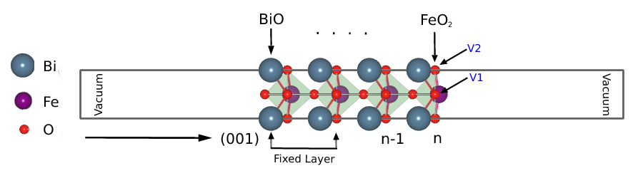
We have systematically studied the TBFO (001) slab structures in the presence of the FM ordering. For this study we have used asymmetrical slab geometries that is the top and the bottom surfaces are oppositely charged. The unit-cell TBFO carries the point-group symmetry. Typically these slab structures are polar in nature, and in this case it comprises of two complementary slices, i.e., a positively charged and a negatively charged layer in the direction. In Fig. 1. the slab structure having two surface mono-layers with two different possible terminations have been presented.
The results presented in this article are for structures obtained after performing ionic relaxation. In the process of ionic relaxation we have kept half of the layers from top to be free for relaxation and rest of the layers to be fixed i.e., clamped to the bulk co-ordinates since our primary focus is to understand the electronic properties of the top surface layers.
In Fig. 1, the snapshot of the two mono-layered (2ml) slabs are given where the surface layers are enumerated. Here, ‘n’ and ‘n-1’ stand for the top and bottom surface layers respectively. For a systematic study of the thickness dependence of the electronic properties we have used structures having 1 (1ml), 2 (2ml) and 3 monolayers (3ml). Furthermore, we have used four different structures of TBFO having lattice constant (‘a’) 3.670dr , 3.770, 3.880 and 3.935 Åwang gp . These structures are labeled as structure-I, structure-II, structure-III and structure-IV respectively.
In our study, structure-II has been found to be most stable and it also hosts the spin-polarized 2DHG at the surface.
The effect of oxygen vacancy on the surface states has been studied, particularly for structure-II. There are two inequivalent sites at which the oxygen vacancies may appear at the top surface. The two different sites for oxygen vacancies, which are named as V1 and V2, have been presented in Fig. 2. Our calculations have been carried out for the terminated slab for all the thicknesses in order to understand the persistence of the 2DHG at the surface.
III Thermodynamic stability
Before presenting the results of the electronic properties, in this section we discuss the thermodynamic stability of the TBFO slabs. The stability of the surface with respect to the bulk can be studied by estimating the surface energy. It is the sum of the cleavage energy (in unit ) of the unrelaxed surface and the relaxation energy (in unit ). The surface energy is defined as,
| (1) |
where and are the cleavage and relaxation energies respectively. The cleavage energy can be defined as the amount of energy required to break a crystal into complementary slices mentioned above. Stoichiometrically, in [001] direction, the TBFO possesses two complementary unrelaxed surfaces i.e., and , which can be obtained by cleaving the bulk crystal. The cleavage energy for the two possible slab structures have been defined in Eqs. 2 and 3 as,
| (2) |
| (3) |
In the above equations, represents the total energy possessed by the bulk TBFO, ‘n’ denotes the total number of BFO monolayers and ‘S’ represents the surface area. It is clear that for the asymmetrical slab structures, the cleavage energies are same for both kind of surface termination. In Table LABEL:Table:cleavage-energies, we have presented the cleavage energies for both kind of surface terminations and for different thickness of the TBFO slab.
| Structures | I | II | III | IV |
|---|---|---|---|---|
| 1ml | 2.15 | 2.61 | 2.99 | 3.12 |
| 2ml | 1.82 | 2.64 | 2.71 | 2.77 |
| 3ml | 1.85 | 2.63 | 2.72 | 2.83 |
The relaxation energy i.e., can be defined as,
| (4) |
where, stands for the relaxed energy of the slab termination and stands for the unrelaxed energy for the slab with the same termination layer. The estimation of the relaxation energies for the two types of termination layer are presented in Tables LABEL:Table:bio-relaxation-energy and LABEL:Table:feo2-relaxation-energy respectively.
| Structures | I | II | III | IV |
|---|---|---|---|---|
| 1ml | -0.81 | -0.42 | 0.05 | 0.11 |
| 2ml | -1.86 | -0.94 | 0.39 | 0.41 |
| 3ml | -2.86 | -1.57 | 0.41 | 0.36 |
| Structures | I | II | III | IV |
|---|---|---|---|---|
| 1ml | -1.53 | -0.59 | -0.19 | -0.23 |
| 2ml | -2.33 | -1.16 | 0.14 | 0.21 |
| 3ml | -3.41 | -1.78 | 0.48 | 0.62 |
Finally, in Tables LABEL:Table:bio-surface-energy and LABEL:Table:feo2-surface-energy our estimation of the surface energies of all the structures for the and surface termination have been presented .
| Structures | I | II | III | IV |
|---|---|---|---|---|
| 1ml | 1.34 | 2.19 | 3.04 | 3.23 |
| 2ml | -0.04 | 1.70 | 3.10 | 3.18 |
| 3ml | -1.01 | 1.06 | 3.13 | 3.19 |
| Structures | I | II | III | IV |
|---|---|---|---|---|
| 1ml | 0.62 | 2.02 | 2.80 | 2.89 |
| 2ml | -0.51 | 1.48 | 2.85 | 2.98 |
| 3ml | -1.56 | 0.85 | 3.20 | 3.46 |
From the data of Tables LABEL:Table:bio-surface-energy and LABEL:Table:feo2-surface-energy, we can observe that the surface energy of structure-I turns out to be negative as the thickness of the surface is increased beyond 1ml. This indicates the possibility of instability in this structure alumina-negative-energy . Apart from these particular cases, the surface energies have been found to be positive in all other cases. It is important to note that from the point of view of surface energy 1ml thick slab of structure-I with termination is the most favorable structure. However, as we move beyond 1ml thickness, the surface energy of the structure-II becomes the lowest among all the structures. Furthermore, it can also be observed that the surface energies are invariably lower when the surface is terminated. Interestingly, it is this terminated structure-II in which we have found the most robust signature of half-metallicity and spin-polarized 2DHG at the surface. Half-metallicity and spin-polarized hole carriers have been found in structure III and IV as well. However, they do not survive in 3ml thick slab structure.
IV Results and Discussions
IV.1 Stoichiometric slabs
IV.1.1
In the thermodynamic analysis of Sec. III it is found that the terminated slabs are more stable compared to the terminated systems. However, it is still important to study the nature of the electronic states in such systems since it is well known that the electronic properties crucially depend on the termination layer (sto-2003 ,sro-sto ). In this line, we have studied the electronic properties of terminated TBFO surfaces in this section.

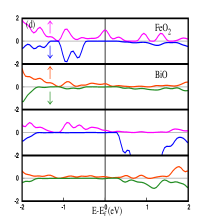
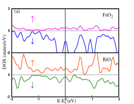
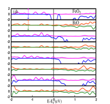
Similar results are found for all the slabs with different thickness in all the structures. Here, only the results for 1ml thickness is presented. In Fig 3, the total density of states(DOS) results for all the structures are presented. Contributions to the DOS from both the and layers are represented separately. Substantial amount of contribution is observed towards the DOS from both the layers. From the DOS, it is evident that at the Fermi energy there are contributions from both the spin channels for all the structures resulting in metallic states at the surface having finite amount of total magnetization. It is important to note that in an earlier work bulk-paper the bulk system was found to host wide range of electronic states for these four different structures. In the bulk, the structure-III and structure-IV were found to be in ferromagnetic metallic phase, while structure-I was a magnetic semiconductor and structure-II showed half-metallic character. However, our current results point towards dramatic change in the electronic properties with reduced dimensionality. In the next section we are going to see that a much richer electronic phases akin to the bulk system can appear when the slabs are terminated.
| Structures | 1ml | 2ml | 3ml | |||
|---|---|---|---|---|---|---|
| I | 2DHG,HMFM | 2DHG,HMFM | 2DHG,HMFM | |||
| II | 2DHG,HMFM | 2DHG,HMFM | 2DHG,HMFM | |||
| III | 2DHG,HMFM | 2DHG | Metal | |||
| IV | 2DHG,HMFM | 2DHG | Metal |
IV.1.2
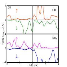
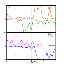
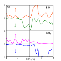
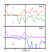
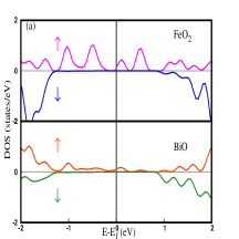
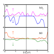
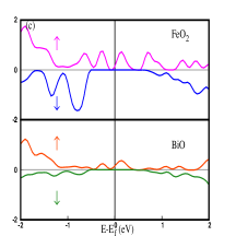
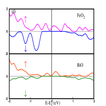
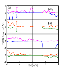
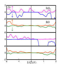
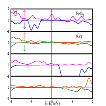
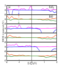
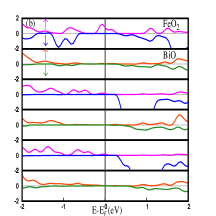
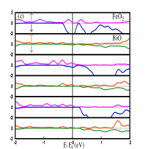
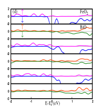
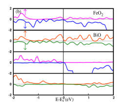
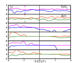
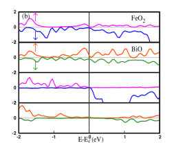
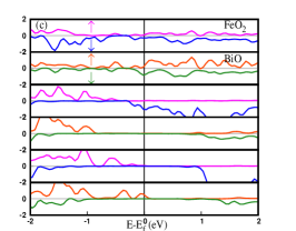
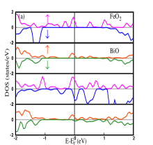
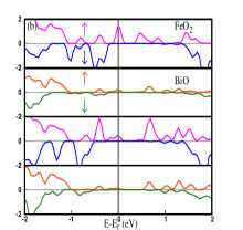
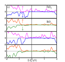
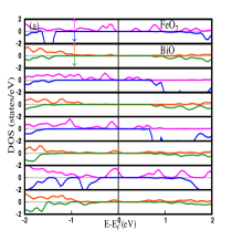
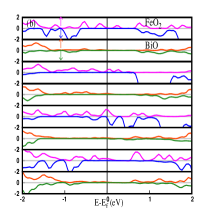
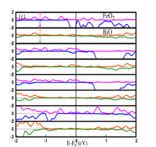
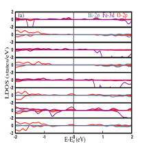
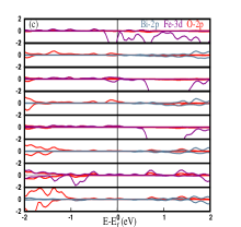
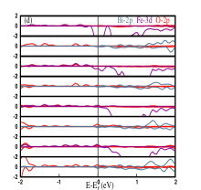
In this section, the results for asymmetrical slab geometries with terminated top layer are presented. All the results are summed up in the Table. LABEL:Table:2deg-hm. We are going to demonstrate that in this case the electronic properties change dramatically as compared with the terminated slab. Furthermore, the electronic properties have been found to be very sensitive to the thickness of the surface layers, except for structure-I. We have performed a systematic analysis of the surface electronic states. These results are presented in Figs. 4, 5 and 6. In Fig. 4, the contribution of each atomic layer towards the DOS for a slab with 1ml thick surface are presented. It can be observed that in this case, each structure shows a weak but clear signature of half-metallic states at the surface. Furthermore, both the and layers contribute hole type charge carriers at the Fermi energy. However, there is a crucial difference between structure-II and all the other structures i.e., it is found to be the most stable structure as we have seen in the thermodynamic analysis III. This indicates that structure-II is the most suitable candidate to explore the possibility of the existence of the 2DHG in this system experimentally. To ascertain if 2DHG persists to higher slab thickness, slab structures with increasing surface mono-layers of 2ml and 3ml also have been studied. The layered DOS for 2ml and 3ml thick surfaces have been presented in Figs. 5 and 6 respectively. It can be observed from Figs. 5(b) and 6(b) that the surface of structure-II yet behaves as HMFM. Furthermore, the charge carriers are still hole type. On the other hand, for structure III and IV the 2DHG survives only upto 2ml thick surface. But these surfaces no more behave as HMFM. However, on further increase of the surface layers to 3ml, the surfaces of these structures become metallic as can be seen from Figs. 6(c) and (d). It is important to note that like structure II, structure-I also hosts half-metallic surface states having hole-type charge carriers all the way upto 3ml thick surface. However, as we have found from our thermodynamic analysis this structure has a tendency to be unstable as the slab thickness grows beyond 1ml, it may not be very suitable to study it experimentally.

| Fl | 1ml | 2ml | 3ml | ||
|---|---|---|---|---|---|
| () | 146.85 | 157.50 | 158.59 | 158.70 | |
| () | 180.00 | 180.00 | 180.00 | 180.00 | |
| O1-Fe | 2.23 | 2.73 | 2.67 | 2.68 | |
| -Fe | 1.91 | 1.87 | 1.87 | 1.87 |
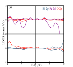
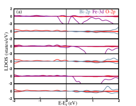
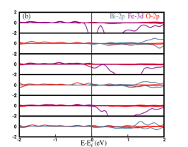
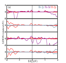
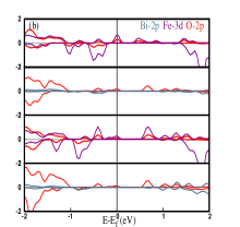
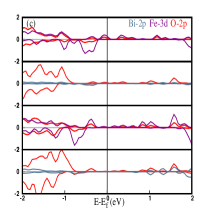
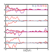
As structure-II is the most stable and preferable structure to search for 2DHG henceforth, this structure is inspected in more detail. To further analyze the orbital contributions towards the 2DHG in this structure, we have computed the local density of states (LDOS). The LDOS results for this structure are presented in Fig. 7. The results for alternative layers i.e., and have been presented separately to understand the orbital contributions from individual layer. For 1ml thick surface the contributions of Fe-3d and O-2p orbitals from the plane and O-2p contribution from the layer can be observed from Fig. 7(a). Similarly, in case of 2ml and 3ml thick surfaces, the contributions towards the LDOS comes solely from the Fe-3d and O-2p orbitals of the surface layers. In addition all the contributions are found from the spin-up component. In general, we have found that Bi does not contribute any states at the surface of any structure. Furthermore the equivalent contributions are found in all other cases except for the 3ml thick surfaces belong to structure-III and IV. The LDOS results for these surfaces have been discussed in Appendix A.
We have also investigated the terminated stoichiometric slabs with full ionic relaxation i.e., without keeping any fixed atomic layers at its bulk atomic position, in order to inquire the presence of the 2DHG at the surface in the full slabs. For this study, the 2ml and 4ml slabs are taken into account. These results are presented in Appendix B.
| Fl | 1ml | 2ml | 3ml | ||
|---|---|---|---|---|---|
| () | 147.70 | 166.34 | 168.17 | 171.43 | |
| () | 180.00 | 180.00 | 180.00 | 180.00 | |
| O1-Fe | 2.30 | 2.46 | 2.37 | 2.27 | |
| -Fe | 1.96 | 1.90 | 1.90 | 1.89 |
Moreover, in order to understand the intricate connection between the structural and electronic properties of the surfaces, we now present the variation in structural parameters e.g., O-Fe-O angle and the O-Fe distance for all the structures. The top surface layer for all the thicknesses are studied in Table LABEL:Table:str-I, LABEL:Table:str-II, LABEL:Table:str-III and LABEL:Table:str-IV belong to structure-I, structure-II, structure-III and structure-IV respectively. In Fig. 1 the equatorial and the axial oxygens are labeled as and respectively. The angle and are named as and respectively. The is found to be same for all the cases i.e. 180°, whereas there is a substantial difference in for the top surface as compared to the fixed layers (Fl). From the Tables, it can be seen that in general has a higher value at the top surface compared to the fixed layers. In addition also varies from structure to structure. The highest difference has been found in the case of structure-II. The for the top layer remains almost constant with the increase of surface thickness in the case of structure-I, III and IV, while in the case of structure-II it increases monotonically.
| Fl | 1ml | 2ml | 3ml | ||
|---|---|---|---|---|---|
| () | 161.19 | 178.78 | 178.28 | 178.28 | |
| () | 180.00 | 180.00 | 180.00 | 180.00 | |
| O1-Fe | 2.11 | 1.94 | 1.98 | 1.97 | |
| -Fe | 1.97 | 1.94 | 1.94 | 1.94 |
The distance at the top layer shows a behavior that is common to all the structures that is, it is lower compared to the fixed layer and it does not change with the increase of the thickness of the surface layers. However, the distance at the top surface for structure-I and structure-II has a completely opposite tendency in comparison to the structures III and IV. From Tables LABEL:Table:str-I and LABEL:Table:str-II we observe that at the top surface of the 1ml thick surface of the structures-I and II, the distance increases to a higher value compared to that in the fixed layers and then it decreases monotonically with further increase in the thickness of the surface layer. However, this distance still remains higher than that in the fixed layers. Interestingly, in the case of structures-III and IV the distance at the top of 1ml thick surface have been found to be lower than that in the fixed layer. It then increases slightly with the increase in the thickness of the surface layer. However, the distance at the top surface always remains lower than the fixed layers. Effectively top layer moves inward in z-direction.
| Fl | 1ml | 2ml | 3ml | ||
|---|---|---|---|---|---|
| () | 162.67 | 179.91 | 179.32 | 179.56 | |
| () | 180.00 | 180.00 | 180.00 | 180.00 | |
| O1-Fe | 2.12 | 1.89 | 1.91 | 1.91 | |
| -Fe | 1.99 | 1.97 | 1.97 | 1.97 |
Next we proceed to discuss the results of magnetic moments of all the structures. As expected, the major contribution to magnetization is due to ‘Fe’, which is similar to the bulk TBFObulk-paper . The ‘Fe’ magnetic moments for each plane of the surface layers have been presented in Table LABEL:Table:5. In contrast to the variable nature of the structural parameters from one structure to the other, the magnetic moment shows an uniform behaviour in some aspect across all the structures. In all the cases, the magnetic moment of ‘Fe’ at the outermost surface layer has been found to be the lowest. As we move below the top layer, the magnetic moment increases and it remains almost same as we move towards the bottom layer. However, there are still some interesting differences that can be observed from data presented in Table LABEL:Table:5. For structure-I and II the magnetic moment of ‘Fe’ at the top surface remains almost the same irrespective of the thickness of the surface layers, while in case of structure-III and IV the magnetic moment of ‘Fe’ remains unchanged upto 2ml thick surface and then it suddenly increases for the 3ml thick surface. It is interesting to note that the 2DHG at the surface is destroyed in this case.
| Structures | 1ml | 2ml | 3ml | |||||||||
|---|---|---|---|---|---|---|---|---|---|---|---|---|
| Structure-I | 3.04 | 3.04 | 3.04 | |||||||||
| 3.65 | 3.65 | |||||||||||
| 3.69 | ||||||||||||
| Structure-II | 2.99 | 2.97 | 2.96 | |||||||||
| 3.72 | 3.73 | |||||||||||
| 3.72 | ||||||||||||
| Structure-III | 2.93 | 2.94 | 3.38 | |||||||||
| 3.77 | 3.75 | |||||||||||
| 3.79 | ||||||||||||
| Structure-IV | 2.94 | 2.94 | 3.53 | |||||||||
| 3.75 | 3.77 | |||||||||||
| 3.77 |
IV.2 Oxygen vacancy
Since we have found that the terminated structure-II is the most suitable candidate to study the existence of the 2DHG at the surface, in this section we have carried out a brief study of the effect of oxygen vacancy on the electronic properties of the surface states in this structure. In Fig. 2 we have indicated the two inequivalent sites of oxygen at the top layer of a 2ml thick surface. The vacancies are generated at either of these two inequivalent positions which are named as ‘V1’ and ‘V2’. In Figs. 8 and 9 we have presented the individual layer resolved DOS for upto 3ml thick surface layers. It is evident from these results that having oxygen vacancy at the top surface immediately leads to the destruction of the 2DHG at the surface layers.
V Conclusions
In conclusions, motivated by the continued search for 2DEG/2DHG in polar perovskites, in this work we have primarily studied its possibility at the surface of the tetragonal (001) slabs in the presence of ferromagnetic ordering. We have studied the surface properties of asymmetrical slabs with the top surface either being or terminated. For an extensive analysis, we have studied four different structures with the each structure having the surface thickness upto 3ml. We have carefully carried out the thermodynamic analysis of each asymmetric slab. In general, we have found that the terminated asymmetrical slabs are thermodynamically more stable as compared to the terminated slabs. In case of the terminated asymmetrical slabs, structure-I turns out to be the most stable structure for a 1ml thick surface layer. However, structure-I becomes unstable with the increase in the thickness of the surface layers. Overall, we have found that the structure-II is the most preferable structure when the thickness of the surface layer becomes larger than 1ml.
Following the thermodynamic analysis, we have investigated the nature of the electronic states at the surface. The terminated surfaces have been found to be a simple ferromagnetic metal for all the structures, and for all the thicknesses. However, the terminated surfaces show much more interesting and exciting electronic properties. For the surface of a 1ml thick surface layer all the structures have been found to be half-metallic. Moreover, the charge carriers have been found to be of hole-type, effectively giving rise to a spin-polarized 2DHG at the surface. In case of structure-II, this spin-polarized 2DHG survives upto 3ml thick layers of the surface, while for structure-III and structure-IV it exists only upto 2ml thick surface. Although, we have found that the 2DHG survives upto 3ml thick surface in the case of structure-I, we do not consider these results for further investigation as we have found this structure to be unstable beyond 1ml thick surface.
From the thermodynamic analysis and the surface electronic states studies, structure-II turns out to possess the highest robustness and is demonstrated as suitable candidate to host 2DHG, and this structure has been investigated further. From the LDOS calculations, we have found that only ‘Fe’ and ’O’ contributes to the 2DHG, while ‘Bi’ has no contribution towards it. Subsequently, we have investigated the fate of the 2DHG in this structure in the presence of oxygen vacancy at the surface. We have found that oxygen vacancy leads to the destruction of the 2DHG, and the surfaces turn out to be metallic.
ACKNOWLEDGEMENTS
The authors would like to thank the computing facility provided by the National Institute of Technology, Rourkela and the computational facility provided by the Science and Engineering Research Board, Department of Science and Technology, India (Grant No: EMR/2015/001227). S. J. is very much grateful to Sanchari Bhattacharya, NIT Rourkela, India for very useful discussions.
Appendix A Local density of states (LDOS)
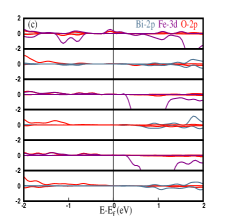
The 2DHG is destroyed in the case of 3ml thick surfaces for structure-III and IV. In order to understand the orbital contribution in these cases, we have studied the local density of states for structure-III and structure-IV. The results are presented in the Fig. 10. In all the cases, along with the Fe-3d and O-2p orbital contributions the role of Bi-2p is also found.


Appendix B Full-slab-study
In this section, the terminated slabs with thicknesses 2ml and 4ml are presented. The results of DOS and LDOS results for full slab geometries where the whole slab structures have been allowed to relax before investigating the electronic properties have been presented. For 2ml thick slab, half-metallic electronic state and 2DHG have been found to persist in all the structures except structure-I. Surprisingly, structure-I turns out to be metallic in this case. The layer resolved DOS for each structure have been presented in Fig. 11. From Fig. 11(a), it is evident that although the top surface of structure-I still exhibits the half-metallicity, the bottom layer shows metallic character. However, it is evident that for the
| Structures | str-I | str-II | str-III | str-IV |
|---|---|---|---|---|
| 2ml | 0.01 | 1.4 | 2.69 | 2.82 |
| 4ml | -2.25 | 0.50 | 3.09 | 1.98 |
rest of the structures only one spin channel contributes at the Fermi energy. Furthermore, it is also clear that the charge carriers are hole type in theses structures. Surprisingly, however, for 4ml thick slab the structure-I turns out to be a half-metal (Fig. 13(a)). However, from the thermodynamic stability analysis (Table LABEL:Table:feo2-relaxation-energy-fs) we find that the surface energy of this structure is negative, which indicates that this structure may not be stable. In case of structure-II, which is thermodynamically most stable a tiny contribution of spin-down electron carriers from the third layer destroys the half-metallic character. In addition, structure-I, II still exhibit the existence of 2DHG. The 2DHG cease to exist in structure-III and IV. From Figs. 13(c) and (d), it is evident that the structure-III and IV behave as metal. To understand the orbital contribution for each structure, we have also presented the LDOS results for the 2ml and 4ml thick slabs in Figs. 12 and 14. From the LDOS results we observe that Bi does not have contribution at the Fermi energy except for 2ml thick slab of structure-I and 4ml thick structure-IV, which are metallic in nature, while contributions from and orbitals are found in both the half-metallic and mettalic cases. From the LDOS results (Fig. 14(b) and (c)) we can observe that Fe-3d orbital contributes these electron carriers.
References
- (1) A. Ohtomo & H. Y. Hwang. Nature, 427,423-426 (2004).
- (2) H. Lee et al., Nature Mater, 17, 231-236 (2018).
- (3) Le Duc Anh et al., Adv. Mater. 32, 1906003(2020).
- (4) R. Pentcheva and W. E. Pickett, Physical Review B 74, 035112(2006).
- (5) R. Oja et al., Physical review letters 109,127207 (2012).
- (6) A. F. Santander-Syro et al., Physical Review B 86, 121107(R) (2012).
- (7) Verònica Vildosola et al., Physical review letters, 110, 206805 (2013).
- (8) Sivadas, N. et al.,Phys. Rev. B, 89, 075303 (2014).
- (9) Yan Yin et al.,Vacuum, 120, 83-88 (2015).
- (10) Ying Xie et al.,J. Phys. Chem. C,111, 6343-6349(2007).
- (11) Roberts I. Eglitis, Applied Surface Science, 358, 556-562(2015).
- (12) Jian-Qing Dai et al., Applied Surface Science, 392, 135-143 (2017).
- (13) L. Jin et al.,Sci Rep, 7, 39698 (2017).
- (14) Xue-Jing Zhang and Bang-Gui Liu, Phys. Chem. Chem. Phys., 20, 24257 (2018).
- (15) S Jena, S Bhattacharya and S Datta,Computational Materials Science. 204,111107(2022).
- (16) R. A. de Groot et al. Phys. Rev. Lett. 50, 2024 (1983) .
- (17) Li Yin et al., Journal of applied physics, 120, 165303 (2016).
- (18) N. Feng et al., ACS applied materials, 7, 10612(2015).
- (19) W. Sun et al., Journal of Materials Chemistry C, 7, 463 (2019).
- (20) Z. Zhang et al., Applied physics letters, 99, 062902 (2011).
- (21) Giannozzi et al., J. Phys.: Condens. Matter, 21 395502(2009).
- (22) P. E. Blöchl, Physical Review B 50, 17953 (1994).
- (23) J. P. Perdew, K. Burke and M. Ernzerhof, Physical review letters 77, 3865 (1996).
- (24) H. J. Monkhorst and J. D. Pack, Phys. Rev. B 13, 5188 (1976).
- (25) M. P. A. T. Methfessel and A. T. Paxton, Physical Review B 40, 3616 (1989).
- (26) D. Ricinschi et al., J.Phys.: Condens. Matter 18, L97-L105 (2006).
- (27) J. Wang et al., Science Reports 299, 1719-1722 (2003).
- (28) H. M. Tütüncü and G. P. Srivastava, Phys. Rev. B 78, 235209 (2008).
- (29) François Bottin, Fabio Finocchi, and Claudine Noguera, Phys. Rev. B 68, 035418 (2003).
- (30) Bongjae Kim and B. I. Min, Phys. Rev. B 89, 195411 (2014).
- (31) Łodziana,Z., Topsøe,NY.& Nørskov,J,Nature Mater. 3,289-293(2004).