Understanding and suppressing backscatter in optical resonators
Abstract
Optical cavities have found widespread use in interfacing to quantum emitters. Concerns about backreflection and resulting loss, however, have largely prevented the placement of optics such as lenses or modulators within high-finesse cavities. In this work, we demonstrate a million-fold suppression of backreflections from lenses within a twisted optical cavity. We achieve this by quantitatively exploring backscatter in Fabry-Pérot resonators, separating the effect into three physical sectors: polarization, mode envelope and spatial mode profile. We describe the impact of each of these sectors, and demonstrate how to minimize backreflections within each. This culminates in measured effective reflectivities below the part-per-billion level for the fundamental mode. Additionally, we show that beams carrying orbital angular momentum experience up to times additional suppression, limited only by the density of states of other cavity modes. Applying these ideas to laser gyroscopes could strongly suppress lock-in, thereby improving sensitivity at low rotation rates.
I Introduction
High-finesse optical cavities are broadly useful across quantum optics, enabling efficient interfaces of individual photons to quantum emitters such as atoms and ions walther2006cavity , quantum dots Yoshle2004 ; Reithmaier2004 , rare-earth ions zhong2018optically ; raha2020optical , and defect centers faraon2012coupling ; riedrich2014deterministic . Intracavity optics, such as lenses or modulators, could radically expand the capabilities of such optical resonators. While refractive elements are used extensively in free space optics, they have thus far remained largely absent from moderate- to high- finesse optical cavities. Concerns about backscatter and loss have typically been presumed to preclude intracavity changes of refractive index, even if anti-reflection (AR) coatings are employed. If these concerns could be addressed, intracavity optics would be transformative, enabling new capabilities for light-matter interaction.
Backscattering has been studied across the electromagnetic spectrum, from microwave to optical frequencies. It is of practical importance for applications in ring lasers Menegozzi1973 ; Haus1985 and gyroscopes Chow1985 ; Etrich1992 , and is fundamentally connected to topological systems lodahl2017chiral . In particular, backscatter immunity is a defining characteristic of topologically protected edge channels, even in the presence of disorder Wang2009 ; Hafezi2011 ; hafezi2013imaging ; Zhang2021 . Elimination of undesired optical backreflections, however, has so far been limited to active Krenz2007 or passive svela2020coherent cancellation.
In this work, we identify three main sectors contributing the the total amount of backreflection: polarization, mode envelope and spatial mode profile. We experimentally and quantitatively explore the effects of each of these sectors, and minimize the total backreflection by optimizing over each. These approaches amount to either suppression of the back-coupling matrix element or reduction of the available density of states for backscattering. We demonstrate that backscattering can be suppressed nearly one million-fold in a twisted optical cavity, allowing for effective reflectivities below 1 part per billion (ppb). We find that engineering the polarization eigenstates of the cavity is the essential tool for achieving this performance. Finally, we show that beams carrying orbital angular momentum (OAM) exhibit even stronger suppression of backreflections due to a topological protection arising from their phase winding.
II Reflector in a cavity
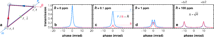
To begin, we consider a running wave optical cavity consisting of three mirrors as shown in Fig. 1a. The two input/output mirrors have amplitude reflection (transmission) coefficients (), while the third mirror is a perfect reflector. An intracavity reflector with amplitude reflection (transmission) coefficient () can couple a forward-traveling mode to a backward-traveling mode. Indeed, even in cavities without an explicit reflector, the mirror imperfections in high-finesse ring cavities can be sufficient to induce detrimental backscattering Krenz2007 .
Using standard input/output field relations siegman86 , the intracavity and output fields for both the forward- and backward-traveling modes may be computed, as shown in Figs. 1(b-e) for various values of . As the intracavity reflectivity increases, the forward and backward modes hybridize until they are fully mixed. Note that the highest reflectivity shown, parts per million (ppm), corresponds approximately to the best (lowest-reflectivity) commercially-available AR coatings. Thus, even at the modest finesse of 4000 shown in Figs. 1(b-e), any optic within the cavity would fully hybridize the forward and backward modes. Note that unlike the case of a standing wave cavity Jayich2008 , sub-wavelength changes of the single reflector’s longitudinal position do not impact the amount of backreflection for the running wave case.
A powerful tool to break the forward-backward symmetry is a non-planar cavity geometry, which provides a round-trip image/polarization rotation Nilsson1989 ; Yelland1994 (an example of a Pancharatnam-Berry phase Pancharatnam1956 ; Berry1984 ). Combined with the Faraday effect, this rotation allows introduction of loss for one polarization state via Brewster reflection and thus unidirectional lasing of an active gain medium within such a cavity Kane1985 ; Maker1993 . For a resonator without gain, this approach fails, making both modes lossy for a large enough coupling between them. Our approach is to instead make the reflection-induced coupling between forward and backward modes vanishingly small, achieved by ensuring that the backward-propagating mode at the same energy has at least the opposite polarization, and potentially also the opposite angular momentum. Traversing a non-planar cavity in the opposite direction reverses the image rotation, breaking inversion symmetry of the system and thus making it helical: the two polarization states of the cavity are split out in frequency (see Appendix A), while forward- and backward-traveling modes of the same helicity remain degenerate Jia2018 . This frequency splitting of the cavity polarization states is the primary feature enabling backreflection suppression.
The total effect of backscattering can be described as a product of matrix elements in three sectors: (i) polarization; (ii) mode envelope; and (iii) transverse mode profile111The latter two could also be thought of as specific cases of a more general “spatial mode profile” sector.. We discuss each of these sectors, finding that sectors (i) and (iii) benefit from non-planarity.
III Polarization sector
We first analyze backreflections in the polarization sector. The eigen-polarizations of a cavity can be found using Jones calculus Jones1941 (see Appendix A). The cavity round-trip Jones matrix is composed of Jones matrices for individual optics arising from birefringence , where is the birefringent phase shift, as well as rotation of the coordinate system into the local and polarization axes, where is the required rotation angle. For twisted cavities, the forward and backward round-trip Jones matrices need not be identical. These Jones matrices, and , can be written as
| (1) |
That is, the order of the index over the cavity optics is reversed for forward versus backward matrices and the rotation angles become negative (and ). As shown in Appendix C, and have the same eigenvalues (and thus resonance energies); however, the eigenstates can differ.
For the case of birefringent phase shifts arising from non-normal incidence on dielectrics in a planar resonator (see Fig. 2a), the forward and backward matrices are the same: . The resulting polarization eigenstates are linear, oriented along the birefringence axes. In a linear polarization basis, the Jones matrix for the reflection operator is . When a polarization eigenmode is backreflected, it is still resonant: reflection acting on an eigenvector of results in an eigenvector of with the same eigenvalue.
For the case of an image rotation only (see Fig. 2c), the backwards-traveling mode image-rotates in the opposite direction. However the -direction inverts as well, so the two Jones matrices are again the same: . The resulting eigen-polarizations are thus circular. Recall that the Jones basis vectors express polarization with respect to propagation direction; that is, they actually describe helicity. Reflection flips the helicity of light, so the Jones matrix for reflection in the circular polarization basis is . Therefore, reflection acting on an eigenvector of gives an eigenvector of with the opposite eigenvalue. That is, for circular polarization states in a twisted cavity (whose Jones matrix is a rotation), backreflections are energetically forbidden. Intuitively, this can be seen from the polarization frequency splitting arising from the circular polarization vector rotating either with or against the image rotation. When a reflection occurs, the image rotation changes sign, but the polarization rotation (i.e., spin angular momentum, not helicity) does not.
To summarize, backreflection of linear polarization states is allowed: light resonant in the forward direction is also resonant in the backward direction. Circularly polarized eigenmodes of a twisted cavity, however, are protected against backreflections. Light of a given polarization mode finds no density of states to backscatter into.
In the general case of both birefringence and rotations, the cavity polarization modes are elliptical (see Fig. 2c). For such a cavity, we can calculate the degree of backreflection suppression from the matrices and . Let and be the eigenvectors of and , with eigenvalues ( and have the same eigenvalues). The matrix element of the reflection operator is then given by
| (2) |
for . The magnitude of this matrix element (squared) quantifies the degree of backreflection allowed in the polarization sector.
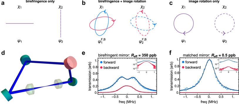
To demonstrate this effect, we measure backreflections in a cavity whose schematic is shown in Fig. 2d. We employ a non-planar cavity with two intracavity plano-convex lenses that act as reflectors. The lenses are super-polished222Polished and coated by Perkins Precision Developments. for low surface roughness ( Å rms) and are AR-coated to ppm at 780 nm. The lower input/output mirrors are designed for zero birefringent phase shift between and polarization at their angle of incidence (AOI)333Designed and manufactured by Five Nine Optics.. Minimizing this phase difference is critical; we found that a coating with specification performed notably better than a different coating with . The upper mirrors have a spatial rotation of between their respective and axes. Thus, if these two mirrors have the same coating, any residual birefringence nearly cancels after reflection off both mirrors, as -polarization for the first mirror very nearly becomes -polarization for the second mirror. We can vary the birefringence by using two upper mirrors from the same coating run (thus canceling birefringence), or by using mirrors from different coating runs, leaving a residual birefringent phase shift. The finesse of this cavity is , set primarily by the input/output mirror transmission (see Appendix B).
The results for backreflections of the fundamental cavity mode are shown in Fig 2. For the birefringent case (Fig. 2e), the forward mode begins to hybridize with the backward mode (cf. Fig. 1). Even in this case, the effective reflectivity ( ppb) is about 700 times lower than the bare reflectivity of the AR-coated lens ( ppm). Furthermore, the above analysis assumes a single reflector, while in reality, this cavity has reflections at 4 lens surfaces. This reduction in reflectivity from the free-space value primarily results from the round-trip image rotation still dominating over the un-canceled birefringence, meaning that the resulting polarization states are still nearly circular. From the measured birefringence of the mirrors, we only expect overlap between the forward and backward cavity polarization modes with the same eigenvalue. There is also another mechanism of backreflection suppression at work related to the spatial mode profile of the cavity mode (see Sec. IV).
For the non-birefringent case, we use mirrors designed for at the AOI of the upper mirrors. Since both upper mirrors come from the same coating run in this case, the spatial rotation between these mirrors cancels much of any residual birefringence of this coating. As shown in Fig. 2f, we see a further 700-fold reduction in backreflections, plunging the effective reflectivity below 1 ppb. This is almost 1 million times lower reflectivity than the best-achievable AR-coatings in free space, and results in a negligibly-perturbed forward-propagating mode. Despite having four changes of refractive index per cavity round trip, the cavity polarization state is sufficiently circular that backreflections are almost entirely forbidden.
IV Spatial mode sectors
In addition to the polarization sector, the spatial mode profile matrix element between the initial and target state must be nonzero to allow backreflection to occur. Due to the image rotation and axial symmetry of the twisted cavity in Fig. 2d, the resulting eigenmodes must be invariant (up to a phase) under rotation and indeed may be shown to be Laguerre-Gauss (LG) modes schine2016synthetic . The LG transverse mode profiles in a two-dimensional plane perpendicular to the propagation axis are given by
| (3) |
where () is the radial (azimuthal) coordinate. The mode indices and are integers with , are generalized Laguerre polynomials, and is the Gouy phase. The local beam waist and wavefront radius of curvature together define the complex beam parameter (-parameter) as , where is the wavelength of the light. The normalization constant ensures that . The three phase factors represent wavefront curvature, Gouy phase, and angular momentum in the form of a phase winding/optical vortex, respectively.
Consider how the cavity mode profiles transform under a reflection. The radial coordinate remains unchanged, while . Since the sign of only matters in the phase winding term, the reflection thus has the effect of taking . That is, the forward-propagating mode with angular momentum has the same phase profile as the backward-propagating mode with angular momentum . Furthermore, the backward-propagating mode at a given plane has the opposite sign wavefront curvature as the forward-propagating mode: if the forward mode has a diverging wavefront at a given plane, the backward mode is converging.
The matrix elements of reflection in the spatial profile sector between forward- and backward-traveling modes with the same mode indices are thus given by
| (4) |
where is the reflection operator, is the plane of the reflector, and () indicates the forward (backward) mode. The -parameter after reflection can be found from action of the reflector’s matrix on the incident -parameter , and is the -parameter of the backward-traveling mode at .
From this expression, we find something noteworthy: regardless of , all of these matrix elements for are zero, as the integral over the angle results in a Kronecker delta . We therefore analyze the and the cases separately. The integral Eq. 4 can be computed in closed form, even for the general case of a curved reflector and for all . The result of the integral is:
| (5) |
where , is the reflector’s radius of curvature in units of the Rayleigh range , and is the -coordinate in units of (where is the waist).
IV.1 Mode envelope

Equation 5 mainly quantifies the observation that a reflection should be well-mode-matched into the backwards traveling mode in order to occur. This is visualized in the left column of Fig. 3. This mode-matching can be increased by turning one lens to be backwards, such that the cavity mode encounters the lens’ flat surface when it is large and less-divergent. This gives better mode-matching of the reflection into the backward mode, and thus a 20 increase in the effective reflectivity (right column of Fig. 3).
For the standard lens orientation, we see from Fig. 3b that , which provides a factor of 50 suppression of backreflections compared to the free space value. This factor of 50 due to mode mismatch accounts for the rest of the reduction of the free space reflectivity to the birefringent value in Fig. 2f.
IV.2 Backreflections with angular momentum
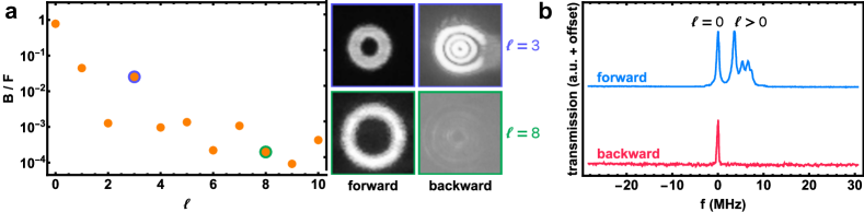
We saw from the -integral in Eq. 4 that LG modes with nonzero angular momentum cannot backreflect into themselves. To experimentally probe this, we increase cavity backreflections by using the birefringent mirror configuration of Fig. 2e, and reversing the orientation of one of the lenses (Fig. 3, bottom row).
Using holographic beam-shaping with a digital micromirror device Zupancic2016 , we inject a desired LG ring mode (i.e., ) into the cavity and observe its backreflection behavior. As shown in Fig. 4a, while shows substantial backscatter, we see backreflection suppression by one to four orders of magnitude for nonzero angular momentum. In fact, by observing both the forward and backward modes on CCD cameras, we find that this backreflection suppression is limited entirely by the availability of other modes to backscatter into. Since the is different from in Eq. 4 (unless the reflector matches the phase front of the cavity mode), the forward and backward mode bases are not mutually orthonormal, so a mode could backscatter into a mode if there happens to be such an accidental near-degeneracy. This can be seen for in Fig 4a. Additionally, imperfections such as misalignment or optical surface wedge can introduce small couplings even between different states. Backreflection should be especially suppressed near intentional degeneracy points schine2016synthetic ; Kollar2015 , where modes cluster up, and accidental degeneracies are less likely.
In the lowest backreflection configuration (non-birefringent, standard lens orientation as in Fig. 2f), backreflections of higher-angular momentum states are unobservably small. The suppression quantified for modes in the higher-backreflection configuration (birefringent, one lens backward) of Fig. 4 indicates that beams carrying orbital angular momentum experience effective reflectivities in the lowest backreflection configuration as low as sub-part-per-trillion.
V Conclusions
We have demonstrated the ability to incorporate optics inside of high-finesse optical cavities. Lenses and modulators could dramatically expand the capabilities of such resonators, as they do for free space optics. By engineering the polarization properties of the cavity eigenmodes, we suppress the effect of intracavity backreflections by six orders of magnitude, resulting in sub-part-per-billion effective reflectivities. Beams carrying orbital angular momentum provide even greater suppression due to their phase winding, limited only by the available density of states for mode conversion, and yielding effective reflectivities at the part-per-trillion level. We have explored the effects on backreflection of both polarization and spatial mode profile in these non-planar cavities.
Unlocking more of the optics toolkit for use in optical resonators could dramatically expand the possibilities for high-cooperativity interfacing with quantum emitters. Aspheric lenses can be used to shape cavity spectra Jaffe2021 , and high-NA systems such as optical tweezers or atom imaging could be Purcell-enhanced. At high-NA, where paraxial approximations break down, new regimes such as strong light-matter coupling in the presence of vector optics effects like spin-orbit coupling zeppenfeld2010calculating ; Naidoo2016 may be explored. Incorporating non-planarity into standard, mirror-only high-finesse ring cavities may also reduce undesired backreflections Krenz2007 .
Acknowledgements.
This work was supported by AFOSR Grant FA9550-18-1-0317, and AFOSR MURIs FA9550-19-1-0399 & FA9550-16-1-0323.Appendix A Polarization eigenstates of a cavity
For most cavities, polarization is an unimportant degree of freedom. The two polarization states typically have the same energies; a degeneracy limited only by stress-induced birefringence in the mirrors of very high finesse 2-mirror cavities Hall2000 , or non-normal mirror incidence in planar running-wave cavities kruse2003cold . For the non-planar cavities we describe here however, there is special structure to the polarization eigenmodes.
Just as ray transfer () matrices are used to calculate the spectra and eigenmodes of an optical resonator siegman86 , Jones matrices Jones1941 can be used to calculate the polarization eigenmodes of a cavity. The round trip Jones matrix of a cavity is calculated by composing the individual Jones matrices of optical elements. The two relevant types of Jones matrices here will be birefringence and spatial rotation.
For a linear phase retarder whose fast axis is aligned with the -axis of the coordinate system, the matrix describing its action on a Jones vector describing a polarization state in the basis of horizontal (; direction) and vertical (; direction) polarization states takes a simple form:
| (6) |
where is the phase retardation between the fast and slow axes. That is, the and basis states acquire a relative phase shift .
For our non-planar cavities, we will rotate the local coordinate system between each optical element over a cavity round trip such that the coordinate -axis indeed corresponds to one of the birefringent axes (the -polarization). These rotation matrices are given by:
| (7) |
For an -optic non-planar cavity, the cavity Jones matrix is then given by
| (8) |
where each optic’s birefringent phase shift is , and is the angle required to rotate the coordinate system at optic into the coordinate system of optic .
Consider a cavity with no rotations, but with a single birefringent phase shift of . This cavity has the round trip Jones matrix . The eigenvectors (and thus, polarization eigenstates) are then simply and , and the eigenvalues are . The round trip phases acquired by the two polarization states differ by , which sets the birefringent polarization mode splitting.
Next, consider a non-birefringent cavity whose Jones vector consists purely of a rotation of nonzero angle , . The polarization eigenstates are then given by
| (9) |
which can be recognized as the left- and right-handed circular polarization states and , respectively.
The eigenvalues are . Thus, the round trip phases acquired by the two polarization states differ by . This corresponds to the circular polarization rotating either with or against the image rotation represented by the rotation matrix. A splitting of these polarization modes arises even in the absence of birefringence.
Note also that each reflection from a cavity mirror also contributes a reflection Jones matrix
| (10) |
written in the basis. The minus sign can be interpreted in a number of ways. In the case of non-normal incidence, it is clear that the tangential axis is reversed under reflection. More generally, including the case of normal incidence, the “polarization” basis states of the Jones calculus are defined with respect to a propagation direction (i.e., they are actually helicity states). This can be seen most clearly in the circular basis, where left- or right-handedness of the rotating electric field is defined with respect to the propagation direction. Upon reflection, the rotation direction of the electric field vector does not change, but the propagation direction does; the helicity therefore changes sign. A reflection thus performs the transformation . Converting this transformation into the basis gives us above.
Appendix B High-finesse lens cavity
The lenses used for the cavities in this work were manufactured by Perkins Precision Developments. They are plano-convex lenses with 5 mm radius of curvature made from Corning 7980-UV-1D fused silica. Both surfaces were super-polished to ultra-low surface roughness, Å rms, and AR-coated to ppm at 780 nm. We found that this ultra-low surface roughness was critical to achieving low loss. Similar lenses with higher surface roughness (not spec’d) led to substantially greater intracavity loss.
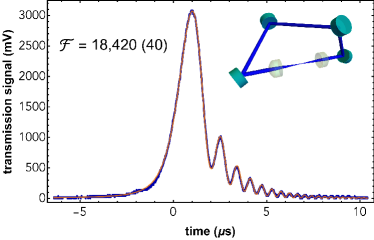
As a demonstration of the cavity finesse possible with such lenses, we show here a twisted cavity where the 4 mirrors used supported a cavity finesse of . After inserting two of these superpolished lenses into the cavity, the resulting finesse was . A cavity ringdown Poirson1997 from which this value was obtained is shown in Fig. 5. This corresponds to a loss of about 80 ppm per lens per round trip (note that each lens contributes two changes of refractive index per round trip).
Appendix C and share eigenvalues
In this appendix, we prove that and , as defined in Eq. 1 have the same eigenvalues. Let denote the spectrum, or set of eigenvalues, of a matrix . This spectrum is invariant under cyclic permutations
| (11) |
as well as the transpose
| (12) |
We also note that the transpose of a product of matrices can be written as the reversed-order product of transposes:
| (13) |
Taking the definitions of and from Eq. 1, we note that can be obtained from by transposing and cyclically permuting. By transposing, we get:
| (14) |
where in the last line we used that is diagonal and that . One cyclic permutation, moving from the first to the last position then gives us . This then allows us to write
| (15) |
which tells us that and have the same eigenvalues.
References
- (1) Walther, H., Varcoe, B. T., Englert, B.-G. & Becker, T. Cavity quantum electrodynamics. Reports on Progress in Physics 69, 1325 (2006).
- (2) Yoshle, T. et al. Vacuum Rabi splitting with a single quantum dot in a photonic crystal nanocavity. Nature 2004 432:7014 432, 200–203 (2004).
- (3) Reithmaier, J. P. et al. Strong coupling in a single quantum dot-semiconductor microcavity system. Nature 432, 197–200 (2004).
- (4) Zhong, T. et al. Optically addressing single rare-earth ions in a nanophotonic cavity. Physical review letters 121, 183603 (2018).
- (5) Raha, M. et al. Optical quantum nondemolition measurement of a single rare earth ion qubit. Nature communications 11, 1–6 (2020).
- (6) Faraon, A., Santori, C., Huang, Z., Acosta, V. M. & Beausoleil, R. G. Coupling of nitrogen-vacancy centers to photonic crystal cavities in monocrystalline diamond. Physical review letters 109, 033604 (2012).
- (7) Riedrich-Möller, J. et al. Deterministic coupling of a single silicon-vacancy color center to a photonic crystal cavity in diamond. Nano letters 14, 5281–5287 (2014).
- (8) Menegozzi, L. N. & Lamb, W. E. Theory of a ring laser. Physical Review A 8, 2103–2125 (1973).
- (9) Haus, H. A., Statz, H. & Smith, I. W. Frequency Locking of Modes in a Ring Laser. IEEE Journal of Quantum Electronics 21, 78–85 (1985).
- (10) Chow, W. W. et al. The ring laser gyro. Reviews of Modern Physics 57, 61–104 (1985).
- (11) Etrich, C., Mandel, P., Centeno Neelen, R., Spreeuw, R. J. & Woerdman, J. P. Dynamics of a ring-laser gyroscope with backscattering. Physical Review A 46, 525–536 (1992).
- (12) Lodahl, P. et al. Chiral quantum optics. Nature 541, 473–480 (2017).
- (13) Wang, Z., Chong, Y., Joannopoulos, J. D. & Soljačić, M. Observation of unidirectional backscattering-immune topological electromagnetic states. Nature 461, 772–775 (2009).
- (14) Hafezi, M., Demler, E. A., Lukin, M. D. & Taylor, J. M. Robust optical delay lines with topological protection. Nature Physics 7, 907–912 (2011). eprint 1102.3256.
- (15) Hafezi, M., Mittal, S., Fan, J., Migdall, A. & Taylor, J. Imaging topological edge states in silicon photonics. Nature Photonics 7, 1001–1005 (2013).
- (16) Zhang, Z., Delplace, P. & Fleury, R. Superior robustness of anomalous non-reciprocal topological edge states. Nature 598, 293–297 (2021).
- (17) Krenz, G., Bux, S., Slama, S., Zimmermann, C. & Courteille, P. W. Controlling mode locking in optical ring cavities. Applied Physics B: Lasers and Optics 87, 643–647 (2007).
- (18) Svela, A. Ø. et al. Coherent suppression of backscattering in optical microresonators. Light: Science & Applications 9, 1–8 (2020).
- (19) Siegman, A. E. Lasers (University Science Books, 1986).
- (20) Jayich, A. M. et al. Dispersive optomechanics: A membrane inside a cavity. New Journal of Physics 10, 095008 (2008). eprint 0805.3723.
- (21) Nilsson, A. C., Gustafson, E. K. & Byer, R. L. Eigenpolarization Theory of Monolithic Nonplanar Ring Oscillators. IEEE Journal of Quantum Electronics 25, 767–790 (1989).
- (22) Yelland, C., Hong, J., Padgett, M. J., Dunn, M. H. & Sibbett, W. A vector approach to the geometrical dependence of polarisation rotation in a non-planar cw Nd:YAG ring laser. Optics Communications 109, 451–456 (1994).
- (23) Pancharatnam, S. Generalized theory of interference, and its applications. Proceedings of the Indian Academy of Sciences - Section A 1956 44:5 44, 247–262 (1956).
- (24) Berry, M. V. Quantal phase factors accompanying adiabatic changes. Proceedings of the Royal Society of London. A. Mathematical and Physical Sciences 392, 45–57 (1984).
- (25) Kane, T. J. & Byer, R. L. Monolithic, unidirectional single-mode Nd:YAG ring laser. Optics Letters 10, 65 (1985).
- (26) Maker, G. T., Ferguson, A. I. & Malcolm, G. P. A. Single-frequency diode-pumped Nd:YAG ring laser with no intracavity elements. Optics Letters 18, 1813 (1993).
- (27) Jia, N. et al. Photons and polaritons in a broken-time-reversal nonplanar resonator. Physical Review A 97, 013802 (2018).
- (28) Jones, R. C. A New Calculus for the Treatment of Optical Systems: I Description and Discussion of the Calculus. Journal of the Optical Society of America 31, 488 (1941).
- (29) Schine, N., Ryou, A., Gromov, A., Sommer, A. & Simon, J. Synthetic landau levels for photons. Nature 534, 671–675 (2016).
- (30) Stone, M., Suleymanzade, A., Taneja, L., Schuster, D. I. & Simon, J. Optical mode conversion in coupled Fabry-Pérot resonators. Optics Letters 46, 21 (2021). eprint 2005.11825.
- (31) Zupancic, P. et al. Ultra-precise holographic beam shaping for microscopic quantum control. Optics Express 24, 13881 (2016). eprint 1604.07653.
- (32) Kollár, A. J., Papageorge, A. T., Baumann, K., Armen, M. A. & Lev, B. L. An adjustable-length cavity and Bose-Einstein condensate apparatus for multimode cavity QED. New Journal of Physics 17, 043012 (2015). eprint 1411.5443.
- (33) Jaffe, M., Palm, L., Baum, C., Taneja, L. & Simon, J. Aberrated optical cavities. Physical Review A 104, 013524 (2021). eprint 2105.05235.
- (34) Zeppenfeld, M. & Pinkse, P. W. Calculating the fine structure of a Fabry-Pérot resonator using spheroidal wave functions. Optics Express 18, 9580–9591 (2010).
- (35) Naidoo, D. et al. Controlled generation of higher-order Poincaré sphere beams from a laser. Nature Photonics 10, 327–332 (2016). eprint 1505.02256.
- (36) Hall, J. L., Ye, J. & Ma, L. S. Measurement of mirror birefringence at the sub-ppm level: Proposed application to a test of QED. Physical Review A - Atomic, Molecular, and Optical Physics 62, 8 (2000).
- (37) Kruse, D. et al. Cold atoms in a high-q ring cavity. Physical Review A 67, 051802 (2003).
- (38) Poirson, J., Bretenaker, F., Vallet, M. & Le Floch, A. Analytical and experimental study of ringing effects in a Fabry–Perot cavity Application to the measurement of high finesses. Journal of the Optical Society of America B 14, 2811 (1997).