Alignment of colloidal rods in crowded environments
Abstract
Understanding the hydrodynamic alignment of colloidal rods in polymer solutions is pivotal for manufacturing structurally ordered materials. How polymer crowding influences the flow-induced alignment of suspended colloidal rods remains unclear when rods and polymers share similar length-scales. We tackle this problem by analyzing the alignment of colloidal rods suspended in crowded polymer solutions, and comparing against the case where crowding is provided by additional colloidal rods in a pure solvent. We find that the polymer dynamics govern the onset of shear-induced alignment of colloidal rods suspended in polymer solutions, and the control parameter for the alignment of rods is the Weissenberg number, quantifying the elastic response of the polymer to an imposed flow. Moreover, we show that the increasing colloidal alignment with the shear rate follows a universal trend that is independent of the surrounding crowding environment. Our results indicate that colloidal rod alignment in polymer solutions can be predicted based on the critical shear rate at which polymer coils are deformed by the flow, aiding the synthesis and design of anisotropic materials.
Unknown University] Okinawa Institute of Science and Technology, Onna-son, Okinawa 904-0495, Japan
1 Keywords
Cellulose nanocrystals, polymer rheology, flow-induced birefringence, rotational diffusion, colloidal rod alignment, Weissenberg number, Péclet number.
2 Introduction
The ability to control the hydrodynamic alignment of colloidal rods is critical to produce structurally ordered soft materials that possess desirable mechanical, thermal, optical, and electrical properties.1, 2, 3, 4, 5, 6, 7, 8 These anisotropic materials are promising in applications ranging from electronic sensors and soft robotics, to tissue engineering and biomedical devices. 5, 9, 10, 11 In material science and engineering, colloidal rods are used in combination with other polymers that impart specific functionality to the final composite material (e.g., increasing ductility and mitigating embrittlement).12, 13, 1 As such, understanding and controlling the hydrodynamic alignment of colloidal rods in polymer matrices becomes of pivotal importance in large-scale processing operations.
Existing literature has shown that the most important control parameter for the onset of hydrodynamic alignment of rigid colloidal rods is the Péclet number , a dimensionless number quantifying the relative strength between the imposed deformation rate (e.g., the shear rate, ) and the rotational diffusion coefficient of the rods ().14, 15, 16, 17, 18 In dilute suspensions, the Péclet number can be defined as , with the rotational diffusion coefficient of the rods given as
| (1) |
where and are the hydrodynamic diameter and length of the colloidal rod, respectively, J/K is the Boltzmann constant, is the absolute temperature, and is the solvent viscosity. For Brownian flocculation dominates, whilst at convective forces are strong enough to induce alignment of the colloidal rods in the flow direction. However, this criterion is only valid under the assumption that the colloidal rods perceive the surrounding fluid as a continuum medium, i.e., the characteristic length scale of the colloidal rods, such as the radius of gyration , must be much larger than that associated with the suspending medium.19, 20, 21 Colloidal rods suspended in low solvents such as water generally satisfy this assumption. However, in many industrial and biological processes, colloidal rods flow in crowded environments of polymers in solution where the characteristic length scale of suspended rods is similar to those of the surrounding macromolecules, e.g., the polymer radius of gyration, , or the polymer mesh size, (also referred to as the correlation length).20, 22, 23, 24, 25, 26, 27 In this scenario, the continuum assumption breaks down and the rods experience a local viscosity () that lies between the solvent viscosity and the bulk viscosity of the polymeric solution.23, 27, 22, 24 In principle, by knowing it is possible to predict the shear rate for the onset of colloidal alignment based on the criterion of using in place of in eqn.1. However, the main hurdle in predicting the alignment of colloidal rods suspended in macromolecular solutions based on the criterion stems from the fact that the value of is not known a priori. Consequently, to date, it is challenging to predict the onset of flow-induced alignment of colloidal rods with comparable length scales to the suspending polymeric fluids.
The flow-induced alignment of rigid elongated particles suspended in viscoelastic polymeric solutions has been studied experimentally and numerically for particles with relevant length scales larger than that associated with the suspending fluid; thus considering the suspending polymeric fluid as a continuum medium for the colloidal rods.28, 26, 29, 30, 31, 32 In this length-scale context, theories predict a critical deformation rate above which the elastic forces of the suspending fluid cause the particle alignment to drift from the flow direction to the vorticity direction.33, 34, 28, 26 However, contrasting experimental results have been reported for relatively small particles suspended in shear-thinning polymeric fluids.26, 29, 30 For instance, elongated hematite particles (with nm) in entangled polyethylene oxide solutions30 displayed the particle alignment in the vorticity direction as expected by theory. However, shorter hematite particles (with nm) suspended in entangled polystyrene solutions26 did not, casting doubts on the validity of continuum theories in conditions where colloids and polymers have similar characteristic length-scales.
In this work, we elucidate the mechanism driving the onset of colloidal rod alignment in semi-dilute polymer solutions where polymers act as the crowding agents to tracer colloidal rods. We use cellulose nanocrystals (CNC) as rigid colloidal rods as they are widely used in synthesis of composite polymer materials with high performance and functionalities.35, 36, 13 To understand the effect of crowding on the CNC alignment, we adopt two approaches: (i) increasing the CNC mass fraction, , in an aqueous Newtonian solvent spanning from the dilute regime where interparticle interactions are negligible up to the semidilute regime where interparticle interactions are at play, providing self-crowding of the CNC by other analogous particles; (ii) Using shear-thinning (non-Newtonian) polymer solutions as the suspending fluid, while keeping so that the CNC is in the dilute regime with negligible interparticle interactions, and the confinement acting on the CNC is provided only by the surrounding polymer chains, which we refer to as polymer-crowding. Specifically, we use high neutral polymers (polyethylene oxide, PEO, and polyacrylamide), with a radius of gyration () comparable to the CNC length scale (i.e., ).37, 38, 39, 40, 23 For the polymer crowding case, we show that the onset of CNC alignment is linked with the relaxation time of the polymer solution (). Specifically, we show that the Weissenberg number , quantifying the strength of the elastic response of the fluid to an imposed deformation rate, controls the onset of CNC alignment in polymeric media.
3 Experimental section
3.1 Test fluids
The test fluids were prepared using an aqueous CNC stock suspension (CelluForce, Montreal, Canada, pH 6.3 at 5.6 wt%). The CNC has an average length nm, a maximum length nm, an average diameter nm as detected from atomic force microscopy.18 The effective hydrodynamic diameter is computed as nm, considering the estimated contribution of the electric double layer nm in deionised water.41 Assuming a cylindrical shape, the number density of the CNC was calculated as where is the hydrodynamic length of the CNC obtained experimentally through (specified in the main text), and is the volume fraction of the suspended CNC (calculated using a CNC density of 1560 Kg/m3).42 CNC suspensions at different mass fraction, , were prepared by dilution of the mother CNC stock with deionised water and mixed on a laboratory roller for at least 24 h at 22 ∘C. Where specified, the CNC suspension was prepared in a Newtonian solvent composed of a glycerol:water mixture containing 17.2 vol% glycerol (Sigma-Aldrich 99% with 1.7 mPa s as measured via shear rheometry).
Polyethylene oxide with MDa, polyethylene oxide with MDa, and polyacrylamide with MDa, referred to as PEO4, PEO8 and PA5, respectively, were purchased from Sigma-Aldrich in powder form and solubilized in deionised water on a laboratory roller for at least 48 h at ∘C (stock solution). Polymer solutions at different concentrations ( in mg/mL) containing a constant amount of CNC were prepared by diluting the polymer stock solution with deionised water followed by dilution of the CNC stock suspension to a final , followed by mixing on a laboratory roller for 24 h at ∘C. Polymer solutions without the CNC were prepared by following the same procedure described above. The polymer concentration where polymers begin to overlap was estimated as , where is the Avogadro’s number. The radius of gyration for the PEO4 and PEO8 was 135 and 202 nm, respectively, estimated as .37, 38 For PA5 nm.39 For the PEO8, the polymer concentrations tested spanned between the dilute () and semidilute unentangled regime, where and the tube diameter , where is the polymer volume fraction and nm is the experimentally determined tube diameter in a PEO melt.40, 23, 43 For PEO8 with nm, the highest polymer concentration tested is which yields nm, thus in the semidilute unentangled regime ( and ).
3.2 Methods
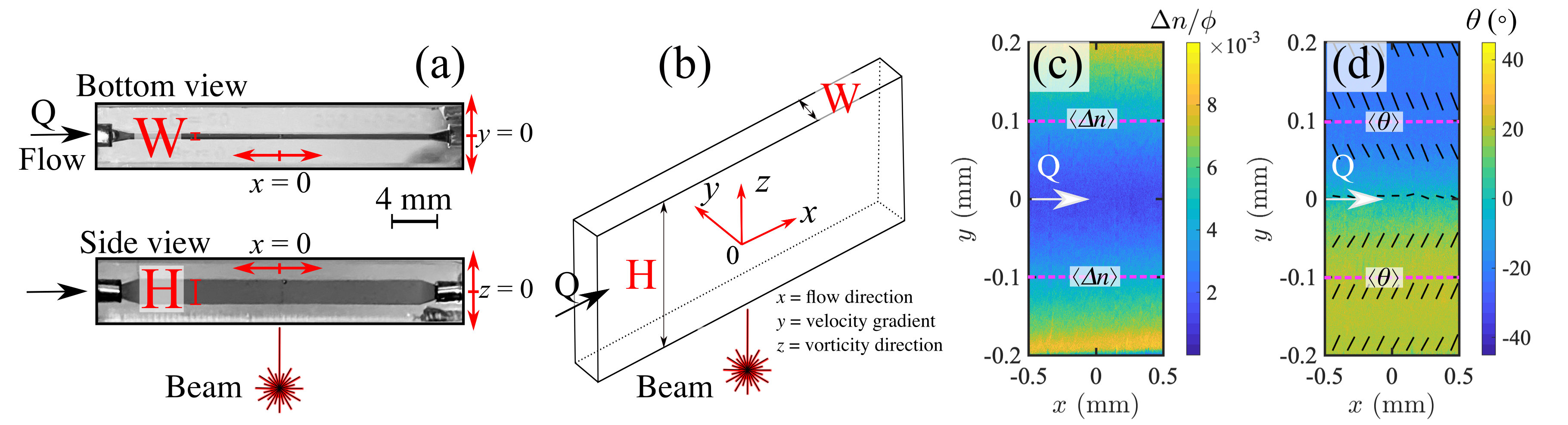
To assess the CNC alignment in crowded environments, we measure the flow-induced birefringence (FIB) as a function of the shear rate in a straight microfluidic channel etched in fused silica (Fig. 1(a,b)). The microfluidic channel has a rectangular cross section with height mm along the -axis, corresponding to the optical path, and width mm, along the -axis, thus providing an approximation to a two-dimensional (2D) Poiseuille flow.44, 18 The flow in the microfluidic channel is driven along the channel length (x-axis) by a syringe pump (Cetoni Nemesys) and Hamilton Gastight syringes infusing and withdrawing at an equal and opposite volumetric flow rate () from the inlet and outlet, respectively. The average flow velocity in the channel is .
3.2.1 Flow-induced birefringence (FIB)
Time-averaged FIB measurements were performed using an Exicor MicroImager (Hinds Instruments, Inc., OR) using a 5 objective at room temperature ( ∘C). The channel is illuminated through the -axis (vorticity direction) using a monochromatic beam of wavelength nm or nm (see Fig. 1(a,b)). The retardance, in nm, and the orientation of the slow optical axis (extraordinary ray), , were obtained from 7 images acquired at 1 s interval and time-averaged. The spatially-resolved (spatial resolution of and is /pixel), and time-averaged, birefringence () and the orientation of the slow optical axis, , are obtained in the flow-velocity gradient plane (- plane) as shown in Fig. 1(c) and (d), respectively, for a representative test fluid of dilute CNC in water. For each flow rate, the birefringence and the absolute value of the orientation of the slow optical axis, , are spatially averaged along 1 mm of the -axis at mm (see dashed lines in Fig. 1(c, d)) and referred to as and , respectively. The background value of acquired at rest was subtracted for all the analysis presented and quantitative analysis of is restricted to . The orientation angle probes the CNC orientation with respect to the flow direction whilst the birefringence intensity, , probes the extent of anisotropy in the system. For fully isotropically oriented particles with colloidal alignment occurring for and . 45, 46 The error related to the spatially averaged and is the standard deviation from the averaging process.
3.2.2 Rheology and flow simulations
Shear rheometry of the test fluids was performed using a strain-controlled ARES-G2 rotational rheometer (TA Instrument Inc.) equipped with a stainless steel cone and plate geometry (50 mm diameter and 1∘cone angle). The test fluids were covered with a solvent trap and measured at 250.1 ∘C (controlled by an advanced Peltier system, TA Instruments). The shear viscosity data were fitted to the Carreau-Yasuda (CY) generalized Newtonian model:
| (2) |
where is the zero-shear-rate viscosity, is the infinite-shear-rate viscosity, is the characteristic shear rate for the onset of shear thinning, is the power law exponent and is a dimensionless fitting parameter that controls the transition to the shear-thinning region. The velocity field along the channel width (, -axis) and the value of shear rate at mm, (the channel location where and are obtained) were computed using numerical simulation. The simulations were performed assuming steady, 1-dimensional, fully developed flow in a planar channel with width , under the imposition of an average velocity . The -component of momentum equation and the CY constitutive equation were discretized and solved using an in-house Finite Element solver 47. In all simulations, 200 linear elements were used across the width of the channel. For each average velocity used during the FIB experiment, and are compared with the effective value of obtained from the simulation at mm. The channel location of mm is chosen to be the midpoint between the side walls ( mm) and the centerline ( mm) so to provide relatively high values of shear rate while avoiding undesired wall effects in the FIB experiment. For very weakly shear-thinning fluids, for which the CY model could not be fitted to the rheological data, the shear rate was computed as for a Newtonian fluid.
4 Results and discussion
4.0.1 Crowding-free
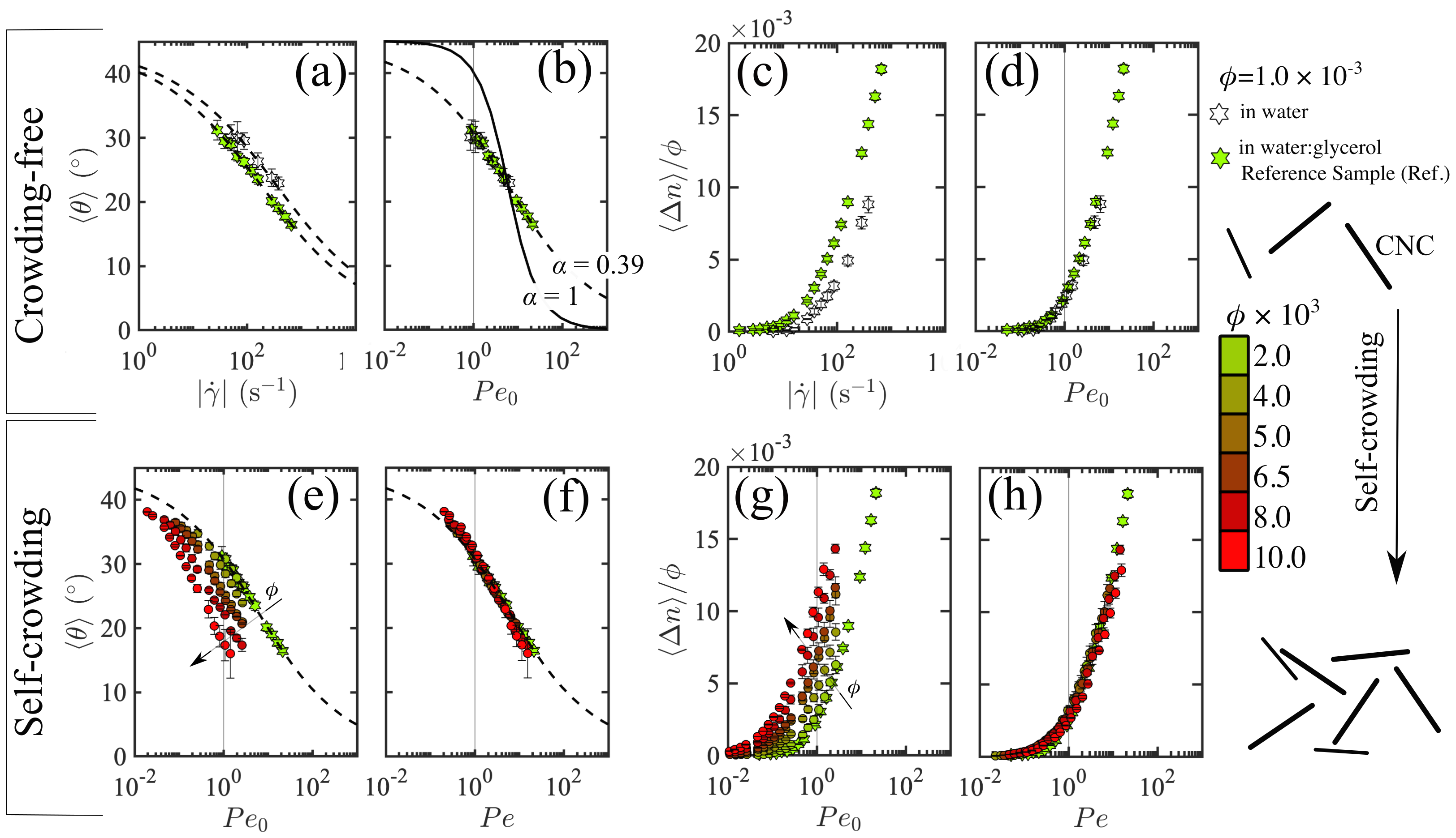
We begin with the evaluation of the FIB of dilute CNC at suspended in an aqueous Newtonian media, either in water ( mPa s) or water:glycerol mixture (17.2 vol% glycerol, mPa s), shown in Fig. 2(a-d). At this relatively low CNC concentration, interparticle interactions are negligible so that each CNC can be considered as isolated and crowding-free.48 Fig. 2(a) and (c) present the and as a function of for the CNC in the crowding-free regime respectively. For both media, the orientation angle, , displays a gradual decrease with (Fig. 2(a)) and, for a given value of , the greater solvent viscosity of the water:glycerol mixture favours the CNC to align with a smaller value of compared to water as the solvent. Moreover, the greater viscosity of the water:glycerol media triggers the onset of CNC alignment at a lower shear rate than in water, as indicated by the onset of birefringence occurring at lower values of (Fig. 2(c)).
The effective rotational diffusion coefficient of the CNC is obtained experimentally based on
| (3) |
where is a stretching exponent that accounts for particle polydispersity.46, 49, 50, 51 For monodisperse particles whilst for polydisperse particles (see solid and dashed line in Fig. 2(b)). Fitting the data in Fig. 2(a) with eqn. 3 yields for both Newtonian solvents, while s-1 and s-1 for the water and water:glycerol solvents respectively. The subscript “0” to indicates the crowding-free regime (i.e., dilute CNC in a continuum medium) and is used to distinguish it from the case where is affected by the surrounding crowding agent. By solving eqn.1 for , using an effective CNC diameter nm accounting for the contribution from the electric double layer,41 and C, we obtain nm, in accordance with the longest CNC population detected via microscopy in our previous work.18 Our experimental data collapse onto master curves when we plot and as a function of the respective Péclet number in the crowding-free regime, , and, the birefringence signal increases sharply at , indicating that the scaling is correct (Fig. 2(b, d)). It is expected that the scaling yields master plots of and only for the systems where the CNC is not experiencing any confinement. It is important to note that, and are complementary parameters to quantify particle alignment during flow. The magnitude of birefringence is linearly related with the number of aligned particles in a given illuminated volume, thus presented in a normalized form as . Contrarily, for a uniform particle alignment, captures a geometrical property of the system that is independent from the number of aligned particles in a given illuminated volume.45
4.0.2 Self-crowding
Following the same approach as for the crowding-free case, we investigate the CNC alignment upon increasing CNC mass fraction , so that analogous particles restrain the motion of each other; a regime that we refer to as self-crowding (Fig. 2(e, h)). As a reference sample we use the crowding-free suspension in water:glycerol mixture (see green star symbol). Increasing the CNC concentration, the values of decrease with increasing (Fig. 2(e)). Analogously, the birefringence onset occurs at smaller values of , corresponding to lower values of (Fig. 2(g)). This behaviour can be explained by the restrained rotational motion of the CNC above the overlap concentration due to particle confinement, leading to a decreasing with increasing . For each sample, can be obtained by fitting the curves in Fig. 2(e) with eqn. 3 using a fixed value of as established in the crowding-free regime. By plotting and as a function of the Péclet number , the curves collapse onto single master curves (Fig. 2(f, h)) and eqn. 3 leads to the dashed line in Fig. 2(f). We note that for , the master curve is set by only considering as scaling factor. Contrarily, for the birefringence , the CNC mass fraction needs to be considered, indeed only scaling the birefringence as enables to collapse the curves onto a master curve.
4.0.3 Polymer-crowding
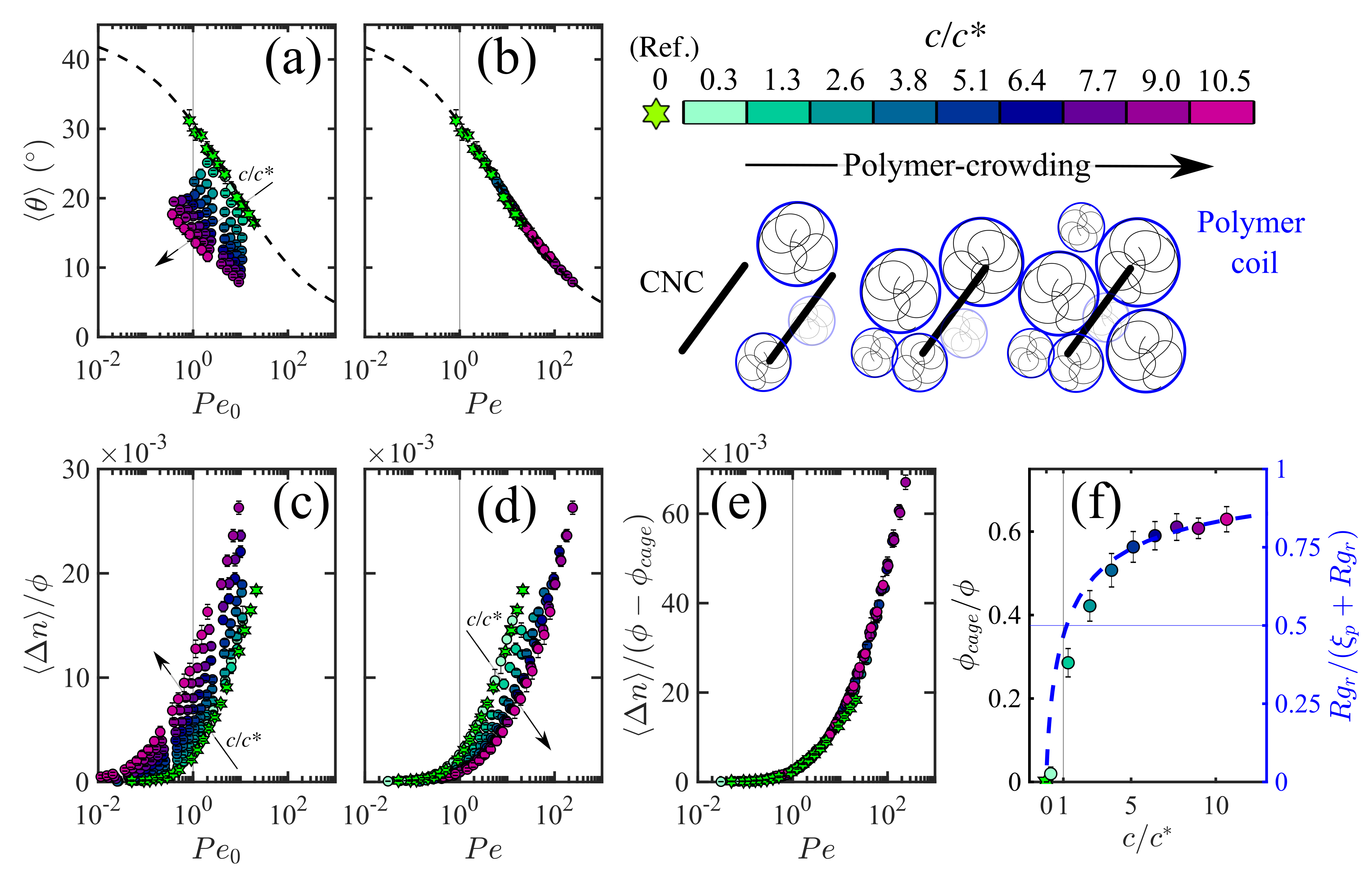
For the case of polymer-crowding we follow and arising from the alignment of diluted CNC () in polymer solutions exposed to a shearing flow. We consider polymers with different and concentrations to achieve viscoelastic polymer solutions with viscosity up to the viscosity of water, and relaxation times s, to provide a large span of crowding environments to the CNC. We use aqueous solutions of polyethylene oxide with MDa and MDa, referred to as PEO4 and PEO8, respectively, and polyacrylamide with MDa, referred to as PA5. In the absence of CNC, these polymer solutions do not display any significant birefringence, ensuring that and signals measured for the CNC dispersions arise exclusively due to the CNC alignment. Here we focus on PEO8 solutions; analysis for the PEO4 and PA5 solutions are given in the ESI Section 2. The confinement imposed on the CNC is tuned by the polymer concentration (), expressed in normalized form as , where is the polymer overlap concentration (Fig. 3). For the PEO8, mg/mL. The PEO8 concentration in the polymer crowded CNC dispersions is varied between the dilute regime, , and the semidilute unentangled regime, where and the tube diameter () is greater than the PEO8 radius of gyration, nm.43 Upon increasing the PEO8 concentration, , the decreases for a given shear rate, thus (see Fig. 3(a)), and the onset of birefringence shifts towards lower values of (Fig. 3(c)). Interestingly, by plotting as a function of , using the values of obtained from the fitting of eqn. 3, the curves collapse onto a master curve (Fig. 3(b)), revealing that the alignment of the CNC occurs in a similar manner for different PEO8 concentrations. Elliptical hematite particles (with nm and cross-section of nm) in entangled PEO solutions have been reported to first orient along the flow direction and then evolve to orientations in the vorticity direction.30 However, within our experimental window, we could only observe increasing as a function of , without the birefringence drop associated with the particle alignment drifting from the flow direction to the vorticity direction.30, 29, 26 Indeed, perfect alignment along the vorticity direction (-axis) for particles with circular cross-sections would lead to isotropic projections in the flow-velocity gradient plane (- plane) with . Similarly to our results, Johnson et al.26 only observed the orientation in the flow direction for elliptical hematite particles (with nm and cross section of nm) in entangled polystyrene solutions.
Different from the self-crowding cases, scaling by is insufficient to collapse the data onto a single master curve (Fig. 3(d)). We re-analyze the data based on the assumption that the failure to collapse might be caused by a small amount of caged CNC () within the PEO8 matrix that remain in an isotropic state, which do not contribute to intensity. Indeed, scaling the by an effective CNC mass fraction enables the data to collapse onto a master curve (Fig. 3(e)). For each , is obtained by minimizing the sum of squared residuals between the reference water:glycerol curve and the polymer-containing samples (detailed procedure is given in the ESI Section 3). The increases with and at , it seems to approach a plateau value (Fig. 3(f)). To corroborate the hypothesis that a portion of CNC is entrapped within the PEO8 network without contributing to the birefringence intensity, it is instructive to understand the evolution of from a topological perspective. As such, we compare the radius of gyration of the CNC, nm, using nm as previously determined from , and nm, with the mesh size of the PEO8 38
| (4) |
as a function of , where nm is the radius of gyration of PEO8. Specifically, we use the ratio to yield values between 0 () and 1 (). Both and the theoretical curve , based on eqn. 4, display a similar trend as a function of , suggesting that is linked to the topological confinement exerted by the polymer mesh size . Thus, at , is a strong function of the polymer concentration, and increases likewise. Contrarily, at , becomes a weaker function of , accordingly, starts to plateau.
Overall, our observations imply that the PEO8 provides a two-way topological hindrance to the CNC rotation, where a fraction of the CNC, , perceives the confinement but is able to align at , whilst the other remaining fraction, , is unable to align in the range of investigated . Contrarily, for the case of self-crowding, all the CNC contribute to the birefringence signals, i.e., . This significant difference between self- and polymer-crowding is associated with the network formed from flexible PEO8 polymer chaining versus the network composed of rigid rod-like CNC. In the following sections we examine the dependence of on relevant length- and time-scales.
4.0.4 Length-scale dependence
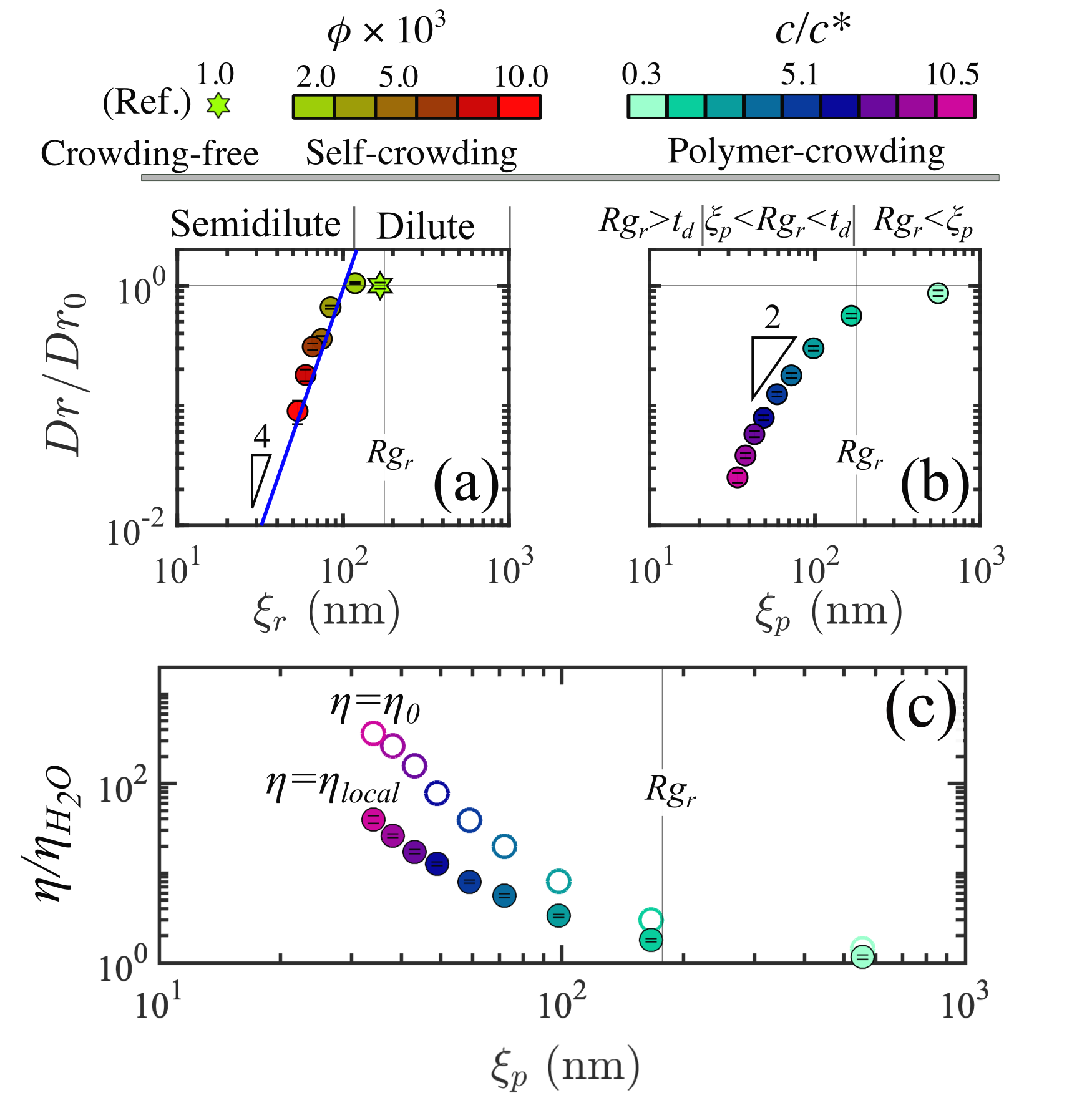
The rotational diffusion coefficient obtained from eqn. 3 captures the impact of the crowding environment on the CNC. To compare the for the case of self- and polymer-crowding, we plot against the statistical mesh size of each crowding agent. The mesh size of the polymer matrix is given by (eqn. 4), whilst for the CNC suspension it is estimated as
| (5) |
where is the number density of the CNC (number of CNC per unit volume).52, 17 For both cases decreases progressively with the decreasing , indicating that the rods progressively sense the local confinement with the decreasing or . However, the CNC follows a much sharper decrease in as a function of for the case of self-crowding than that of the polymer-crowding, indicating that the mesh size alone is not able to fully capture the dependence of from the crowding agent. The trend for the self-crowding case shown in Fig. 4(a) meets the expectation from rigid-rod theory where in the dilute regime is concentration independent and . Whilst in the semidilute (self-crowding) regime, the CNC motion is constrained by the surrounding rods and becomes concentration dependent.53 The dependence of with the rod concentration has been described by the tube model in the framework of the Doi-Edwards theory, assuming that particles are rigid and monodisperse rods in the semidilute regime, as
| (6) |
where is a length-independent prefactor.53, 54, 55 Recently, Lang et al.17 experimentally validated for monodisperse colloidal rods that as previously found from computer simulation.56 Rearranging eqn. 6 with eqn. 5, we obtain
| (7) |
Although polydisperisity is not accounted for in the Doi-Edwards theory, it is interesting to note that the scaling captures the trend for the self-crowding case (Fig. 4(a)). Moreover, using and nm in eqn. 7, it is possible to quantitatively capture the increasing with in the semidilute (self-crowding) regime (see line in Fig. 4(a)).
For the polymer-crowding case, we take inspiration from prior work on the translational and rotational diffusions of nanorods in PEO solutions.20, 22 Specifically, we adopt the scaling law developed by Cai et al.20, 22, by considering as the characteristic dimension of CNC. The majority of the data fall in the “intermediate regime” where , annotated above Fig. 4(b). In this regime, the scaling theory predicts , which captures our trend reasonably well.20 We have also used other polymeric solutions (PEO4 and PA5) to gain further understanding of the polymer-crowding cases. We confirm that the mesh size alone is unable to fully describe the dependence of from the crowding agent, thus, the curves of vs. do not collapse onto a master curve (see ESI, Fig. S3). Since CNC in the PEO8 solutions are in the dilute regime (), it is instructive to evaluate the local viscosity experienced by the particles, , as 57, 24, 58, 23
| (8) |
We use s-1 determined in water with being the water viscosity and obtained experimentally from eqn. 3 (plotted in Fig. 4(a)), to retrieve . In Fig. 4(c), the zero-shear-rate viscosity obtained from bulk rheology (details in Fig. 5(b)) is compared to , displaying in the investigated range of . The mismatch between and indicates that the CNC do not perceive the surrounding medium as a continuum, thus experiencing a viscosity that lies between the water viscosity () and the macroscopic bulk viscosity of the polymer solutions. Consequently, predicting the minimum shear rate required to induce CNC alignment in polymer crowds, based on the criterion (i.e., ), using the bulk viscosity as the solvent viscosity in eqn. 1, would fail by underestimating .
4.0.5 Time-scale dependence
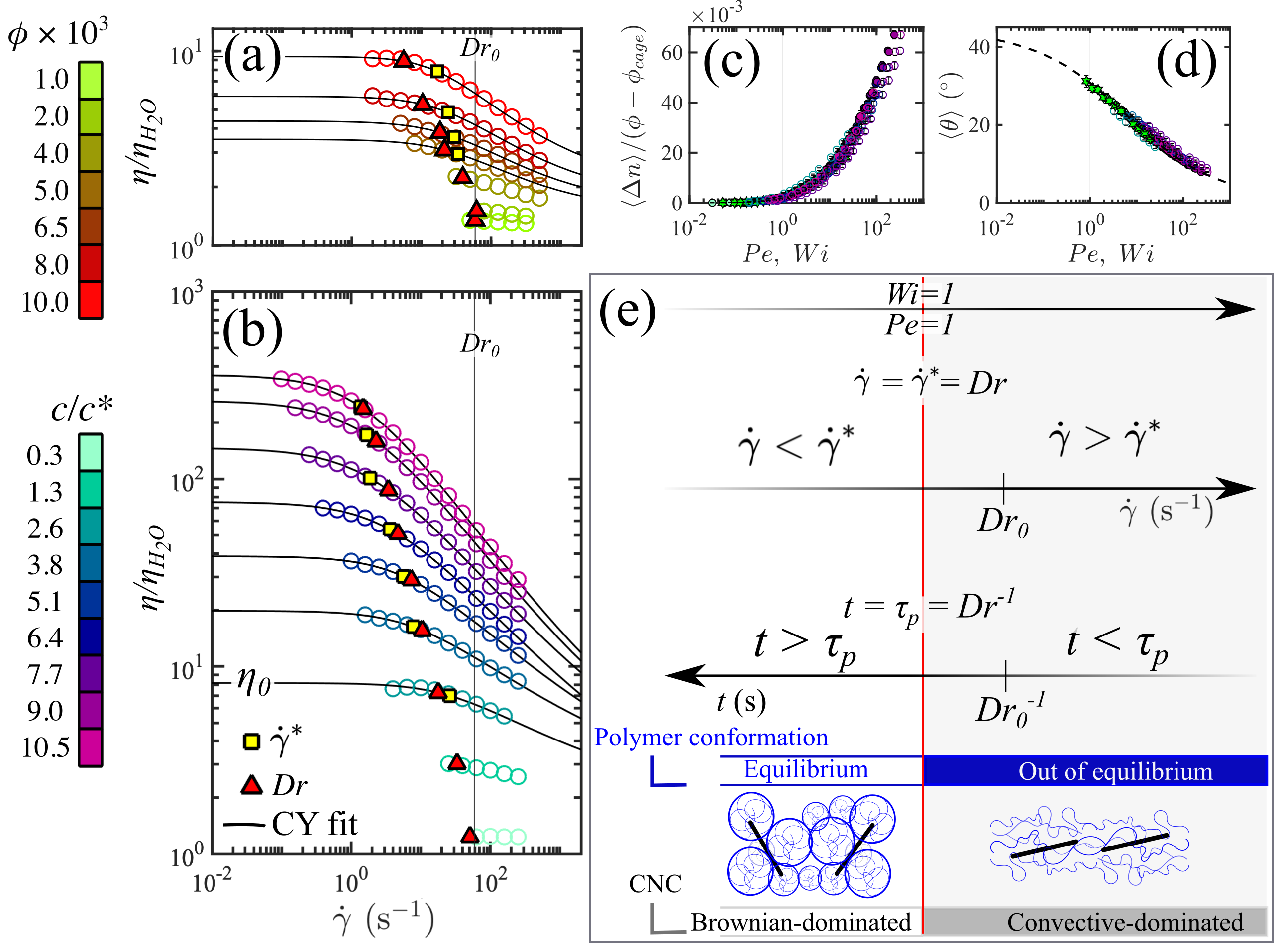
Flow curves obtained from bulk shear rheometry were used to probe the two crowding agents, CNC suspensions in water and PEO8 solutions in the absence of CNC, under different shear rates and related flow time scales (i.e., ), see Fig. 5(a, b). It is important to note that the presence of CNC at in the PEO8 solutions did not alter the bulk rheology (see ESI, Fig. S1). With increasing concentrations of the crowding agent ( and for the CNC and PEO8, respectively), the shear viscosity increases and the onset of shear-thinning, captured by from the CY model (eqn. 2), shifts to lower values of shear rate (depicted by the yellow squares in Fig. 5(a, b)). The obtained via birefringence measurements (as shown in Fig. 4(a, b)) are marked as triangular red symbols on the respective plots of the CNC suspensions and PEO8 solutions.
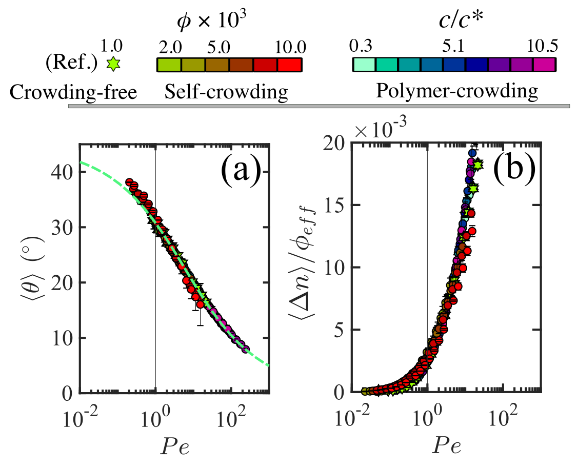
For the CNC suspensions (Fig. 5(a)), obtained from shear rheometry and obtained via birefringence measurements have similar values because the onset of shear-thinning correlates with the onset of CNC alignment. Therefore, the physical interpretation for the decreasing as a function of mirrors the one given for . Specifically, in the semi-dilute (self-crowding) regime, the rods perceive the surrounding rods, enabling the onset of alignment at values of shear rate that decrease progressively with increasing . For the PEO8 solutions (Fig. 5(b)), the onset of shear-thinning, , corresponds to the longest relaxation time of the polymer solution as . In good approximation, the CNC alignment in PEO8 occurs at a shear rate (see yellow squares and red triangles in Fig. 5(b)), suggesting that the onset of CNC alignment is coupled with the polymer relaxation time as . As such, a suitable control parameter for the CNC alignment is the Weissenberg number, , quantifying the strength of the elastic response of the fluid to an imposed deformation rate, where for the polymers are in their equilibrium conformation whilst for the relatively high flow rate drives the polymers out of their equilibrium conformation.59, 60, 61 Based on the relationship , the Weissenberg and Péclet numbers become identical because the rotational diffusion time-scale of the CNC rods is the same as the longest relaxation time of the polymer for the regime investigated here (analogous results are also obtained for the PEO4 and PA5 solutions presented in ESI, Fig. S4). Consistently, the trend of CNC alignment in PEO8 solutions captured by and as a function of is also well described by , with the onset of CNC alignment occurring at (Fig. 5(c, d)). This is remarkably different from previous reports of elliptical hematite particles suspended in PEO solutions in the regime , where the onset of alignment occurs at 30. Similarly, the onset of alignment of carbon nanotubes in sheared polymer melt was observed at , ruling out the coupling of with for relatively large colloids ().29 From a topological perspective, the coupling between tracer particles and the polymer dynamics is predicted by Cai et al.20 in the regime with the scaling (see Fig. 4(b)). It is possible to conceptualize the coupling of with by analysing three distinct time-scales at play during flow as conceptualized in Fig. 5(e). For () the polymer is relaxed and in its equilibrium configuration as the probed time scales are long enough to enable polymer relaxation, during which the CNC is able to escape from the transient confinement provided by the polymer mesh, thus Brownian diffusion dominates. Increasing the shear rate we reach () where the polymer is driven out of its equilibrium conformation and deformed by the flow. At this time scale the CNC perceives the surrounding polymer as a static mesh that provides confinement and aids CNC alignment at values of (). At higher values of shear rate, (), the CNC continues to align with the flow, following a universal curve of and with respect to for a wide range of polymer concentrations in the semidilute unentangled regime as shown by the master curves in Fig. 3(b, e). We note that the CNC alignment for the polymer- and self-crowding case display analogies. In Fig. 6 we plot together and as obtained for all the polymer- and self-crowding cases presented above. The CNC alignment can be described by the same master curve of and vs. . This observation implies that both self- and polymer-crowding of the CNC only alters the critical shear rate for the onset of alignment, but the subsequent trend in alignment for remains the same for both cases. This universal trend with respect to the crowding agent is likely caused by the inability of the CNC to explore the surrounding confinement once the alignment is triggered by a sufficiently high shear rate (i.e., ).17 Note that in our present study the characteristic polymer time-scale is greater than the rotational diffusion time-scale of the CNC in the crowding-free regime, (), see vertical line in Fig. 5(b). However, colloidal rods with slower rotational dynamics in the crowding-free regime compared to the characteristic polymer time-scale, will be in the regime (). Practically, this regime can be achieved by increasing the length of the colloidal rods (), and/or decreasing the polymer molecular weight. As the regime is approached, by for instance increasing , the colloidal rods will progressively experience the surrounding environment as a continuum rather than a discrete medium and . Therefore, for () the onset of colloidal alignment is expected to be dominated by the bulk viscosity of the surrounding polymer solution.19
4.1 Conclusions
We tackle an industrially relevant problem from a fundamental perspective: the control over the alignment of rod-like colloids in polymeric matrices. Specifically, we compare the flow-induced alignment of rigid colloidal rods, namely CNC, in two contrasting crowded environments referred to as self- and polymer-crowding. By analysis of the length- and time-scale, we find that rotational diffusion coefficient, , of CNC in high molecular weight polymeric crowds is coupled with the longest relaxation time of the surrounding polymer, . On this ground, we propose the Weissenberg number as the control parameter for the alignment of colloidal rods that possess similar length-scales as the suspending polymer fluid, ; i.e., in conditions where the continuum approach breaks down. Specifically, we show that by knowing from rheological tests, it is possible to predict the critical shear rate for the onset of colloidal alignment in polymeric fluids as , equivalently , without relying on the knowledge of the local viscosity experienced by the colloidal rods, . In conclusion, our results provide crucial insights on the dynamics of colloidal rods under shearing flows that will aid the production of composite materials with desired structural organization. Additionally, the ability of tracer colloidal rods to probe the relaxation times of the surrounding polymers opens the opportunity to perform in-situ and spatially-resolved characterisation of the dynamics of polymeric fluids under flow using tracer colloidal rods. With further optimisation (e.g., size and composition of the colloidal rods), this technique is promising for analysing polymer dynamics in complex flows encountered in real-life conditions where the investigation is a significant challenge. As a natural next step to our work, we envisage future studies where self- and polymer-crowding are at play jointly, mirroring actual industrial conditions. We use CNC as industrially relevant colloidal rods but the basic principles will also apply to other anisotropic, rod-like, colloidal particles.
5 Acknowledgements
The authors gratefully acknowledge the support of Okinawa Institute of Science and Technology Graduate University with subsidy funding from the Cabinet Office, Government of Japan. V.C, SV, S.J.H. and A.Q.S. also acknowledge financial support from the Japanese Society for the Promotion of Science (JSPS, Grant Nos. 22K14738, 22K14184, 18K03958, 18H01135, and 21K03884) and the Joint Research Projects (JRPs) supported by the JSPS and the Swiss National Science Foundation (SNSF).
6 Competing interests
The authors declare no competing interests.
7 Additional information
Supplementary information is available for this paper.
References
- Li et al. 2021 Li, K. et al. Alignment of cellulose nanofibers: Harnessing nanoscale properties to macroscale benefits. ACS Nano 2021, 15, 3646–3673
- Mittal et al. 2018 Mittal, N.; Ansari, F.; Gowda Krishne, V.; Brouzet, C.; Chen, P.; Larsson, P. T.; Roth, S. V.; Lundell, F.; Wågberg, L.; Kotov, N. A.; Söderberg, L. D. Multiscale control of nanocellulose assembly: Transferring remarkable nanoscale fibril mechanics to macroscale fibers. ACS Nano 2018, 12, 6378–6388
- Shen et al. 2021 Shen, Y.; Levin, A.; Kamada, A.; Toprakcioglu, Z.; Rodriguez-Garcia, M.; Xu, Y.; Knowles, T. P. J. From protein building blocks to functional materials. ACS Nano 2021, 15, 5819–5837
- Xin et al. 2019 Xin, G.; Zhu, W.; Deng, Y.; Cheng, J.; Zhang, L. T.; Chung, A. J.; De, S.; Lian, J. Microfluidics-enabled orientation and microstructure control of macroscopic graphene fibres. Nature Nanotechnology 2019, 14, 168–175
- Sydney Gladman et al. 2016 Sydney Gladman, A.; Matsumoto, E. A.; Nuzzo, R. G.; Mahadevan, L.; Lewis, J. A. Biomimetic 4D printing. Nature Materials 2016, 15, 413–418
- Sano et al. 2018 Sano, K.; Ishida, Y.; Aida, T. Synthesis of anisotropic hydrogels and their applications. Angewandte Chemie - International Edition 2018, 57, 2532–2543
- Peng et al. 2018 Peng, J.; Calabrese, V.; Veen, S. J.; Versluis, P.; Velikov, K. P.; Venema, P.; van der Linden, E. Rheology and microstructure of dispersions of protein fibrils and cellulose microfibrils. Food Hydrocolloids 2018, 82, 196–208
- Håkansson et al. 2014 Håkansson, K. M. O.; Fall, A. B.; Lundell, F.; Yu, S.; Krywka, C.; Roth, S. V.; Santoro, G.; Kvick, M.; Prahl Wittberg, L.; Wågberg, L.; Söderberg, L. D. Hydrodynamic alignment and assembly of nanofibrils resulting in strong cellulose filaments. Nature Communications 2014, 5, 4018
- Pei et al. 2015 Pei, X.; Zan, T.; Li, H.; Chen, Y.; Shi, L.; Zhang, Z. Pure anisotropic hydrogel with an inherent chiral internal structure based on the chiral nematic liquid crystal phase of rodlike viruses. ACS Macro Letters 2015, 4, 1215–1219
- Kiriya et al. 2012 Kiriya, D.; Kawano, R.; Onoe, H.; Takeuchi, S. Microfluidic control of the internal morphology in nanofiber-based macroscopic cables. Angewandte Chemie - International Edition 2012, 51, 7942–7947
- De France et al. 2017 De France, K. J.; Yager, K. G.; Chan, K. J. W.; Corbett, B.; Cranston, E. D.; Hoare, T. Injectable anisotropic nanocomposite hydrogels direct in situ growth and alignment of myotubes. Nano Letters 2017, 17, 6487–6495
- Kokkinis et al. 2015 Kokkinis, D.; Schaffner, M.; Studart, A. R. Multimaterial magnetically assisted 3D printing of composite materials. Nature Communications 2015, 6, 8643
- Wanasekara and Eichhorn 2017 Wanasekara, N. D.; Eichhorn, S. J. Injectable highly loaded cellulose nanocrystal fibers and composites. ACS Macro Letters 2017, 6, 1066–1070
- Doi, M.; Edwards 1986 Doi, M.; Edwards, S. F. The Theory of Polymer Dynamics; 1986; pp 289–323
- Lang et al. 2016 Lang, C.; Kohlbrecher, J.; Porcar, L.; Lettinga, M. The connection between biaxial orientation and shear thinning for quasi-ideal rods. Polymers 2016, 8, 291
- Corona et al. 2018 Corona, P. T.; Ruocco, N.; Weigandt, K. M.; Leal, L. G.; Helgeson, M. E. Probing flow-induced nanostructure of complex fluids in arbitrary 2D flows using a fluidic four-roll mill (FFoRM). Scientific Reports 2018, 8, 15559
- Lang et al. 2019 Lang, C.; Kohlbrecher, J.; Porcar, L.; Radulescu, A.; Sellinghoff, K.; Dhont, J. K. G.; Lettinga, M. P. Microstructural understanding of the length- and stiffness-dependent shear thinning in semidilute colloidal rods. Macromolecules 2019, 52, 9604–9612
- Calabrese et al. 2021 Calabrese, V.; Haward, S. J.; Shen, A. Q. Effects of shearing and extensional flows on the alignment of colloidal rods. Macromolecules 2021, 54, 4176–4185
- Wyart and De Gennes 2000 Wyart, F. B.; De Gennes, P. G. Viscosity at small scales in polymer melts. European Physical Journal E 2000, 1, 93–97
- Cai et al. 2011 Cai, L. H.; Panyukov, S.; Rubinstein, M. Mobility of nonsticky nanoparticles in polymer liquids. Macromolecules 2011, 44, 7853–7863
- Koenderink et al. 2003 Koenderink, G. H.; Zhang, H.; Aarts, D. G. A. L.; Lettinga, M. P.; Philipse, A. P.; Nägele, G. On the validity of Stokes–Einstein–Debye relations for rotational diffusion in colloidal suspensions. Faraday Discussions 2003, 123, 335–354
- Alam and Mukhopadhyay 2014 Alam, S.; Mukhopadhyay, A. Translational and rotational diffusions of nanorods within semidilute and entangled polymer solutions. Macromolecules 2014, 47, 6919–6924
- Hess et al. 2020 Hess, M.; Gratz, M.; Remmer, H.; Webers, S.; Landers, J.; Borin, D.; Ludwig, F.; Wende, H.; Odenbach, S.; Tschöpe, A.; Schmidt, A. M. Scale-dependent particle diffusivity and apparent viscosity in polymer solutions as probed by dynamic magnetic nanorheology. Soft Matter 2020, 16, 7562–7575
- Gratz and Tschöpe 2019 Gratz, M.; Tschöpe, A. Size effects in the oscillatory rotation dynamics of Ni nanorods in poly(ethylene oxide) solutions. Macromolecules 2019, 52, 6600–6612
- Smith et al. 2021 Smith, M.; Poling-Skutvik, R.; Slim, A. H.; Willson, R. C.; Conrad, J. C. Dynamics of flexible viruses in polymer solutions. Macromolecules 2021, 54, 4557–4563
- Johnson et al. 1990 Johnson, S. J.; Salem, A. J.; Fuller, G. G. Dynamics of colloidal particles in sheared, non-Newtonian fluids. Journal of Non-Newtonian Fluid Mechanics 1990, 34, 89–121
- Lee et al. 2017 Lee, J.; Grein-Iankovski, A.; Narayanan, S.; Leheny, R. L. Nanorod mobility within entangled wormlike micelle solutions. Macromolecules 2017, 50, 406–415
- Iso et al. 1996 Iso, Y.; Cohen, C.; Koch, D. L. Orientation in simple shear flow of semi-dilute fiber suspensions 2. Highly elastic fluids. Journal of Non-Newtonian Fluid Mechanics 1996, 62, 135–153
- Hobbie et al. 2003 Hobbie, E. K.; Wang, H.; Kim, H.; Lin-Gibson, S.; Grulke, E. A. Orientation of carbon nanotubes in a sheared polymer melt. Physics of Fluids 2003, 15, 1196–1202
- Gunes et al. 2008 Gunes, D.; Scirocco, R.; Mewis, J.; Vermant, J. Flow-induced orientation of non-spherical particles: Effect of aspect ratio and medium rheology. Journal of Non-Newtonian Fluid Mechanics 2008, 155, 39–50
- D’Avino and Maffettone 2015 D’Avino, G.; Maffettone, P. Particle dynamics in viscoelastic liquids. Journal of Non-Newtonian Fluid Mechanics 2015, 215, 80–104
- D’Avino et al. 2019 D’Avino, G.; Hulsen, M. A.; Greco, F.; Maffettone, P. L. Numerical simulations on the dynamics of a spheroid in a viscoelastic liquid in a wide-slit microchannel. Journal of Non-Newtonian Fluid Mechanics 2019, 263, 33–41
- Leal 1975 Leal, L. G. The slow motion of slender rod-like particles in a second-order fluid. Journal of Fluid Mechanics 1975, 69, 305–337
- Cohen et al. 1987 Cohen, C.; Chung, B.; Stasiak, W. Orientation and rheology of rodlike particles with weak Brownian diffusion in a second-order fluid under simple shear flow. Rheologica Acta 1987, 26, 217–232
- Hasegawa et al. 2020 Hasegawa, H.; Horikawa, Y.; Shikata, T. Cellulose nanocrystals as a model substance for rigid rod particle suspension rheology. Macromolecules 2020, 53, 2677–2685
- Eichhorn 2011 Eichhorn, S. J. Cellulose nanowhiskers: Promising materials for advanced applications. Soft Matter 2011, 7, 303–315
- Devanand and Selser 1991 Devanand, K.; Selser, J. C. Asymptotic behavior and long-range interactions in aqueous solutions of poly(ethylene oxide). Macromolecules 1991, 24, 5943–5947
- Holyst et al. 2009 Holyst, R.; Bielejewska, A.; Szymański, J.; Wilk, A.; Patkowski, A.; Gapiński, J.; Żywociński, A.; Kalwarczyk, T.; Kalwarczyk, E.; Tabaka, M.; Ziȩbacz, N.; Wieczorek, S. A. Scaling form of viscosity at all length-scales in poly(ethylene glycol) solutions studied by fluorescence correlation spectroscopy and capillary electrophoresis. Physical Chemistry Chemical Physics 2009, 11, 9025–9032
- François et al. 1979 François, J.; Sarazin, D.; Schwartz, T.; Weill, G. Polyacrylamide in water: molecular weight dependence of and and the problem of the excluded volume exponent. Polymer 1979, 20, 969–975
- Senses et al. 2016 Senses, E.; Faraone, A.; Akcora, P. Microscopic chain motion in polymer nanocomposites with dynamically asymmetric interphases. Scientific Reports 2016, 6, 29326
- Bertsch et al. 2017 Bertsch, P.; Isabettini, S.; Fischer, P. Ion-induced hydrogel formation and nematic ordering of nanocrystalline cellulose suspensions. Biomacromolecules 2017, 18, 4060–4066
- Wagner et al. 2010 Wagner, R.; Raman, A.; Moon, R. Transverse elasticity of cellulose nanocrystals via atomic force microscopy. 10th International Conference on Wood & Biofiber Plastic Composites 2010, 309–316
- Rubinstein et al. 2003 Rubinstein, M.; Colby, R. H., et al. Polymer Physics; Oxford University Press, New York, 2003; Vol. 23
- Haward et al. 2018 Haward, S. J.; Toda-Peters, K.; Shen, A. Q. Steady viscoelastic flow around high-aspect-ratio, low-blockage-ratio microfluidic cylinders. Journal of Non-Newtonian Fluid Mechanics 2018, 254, 23–35
- Vermant et al. 2001 Vermant, J.; Yang, H.; Fuller, G. G. Rheooptical determination of aspect ratio and polydispersity of nonspherical particles. AIChE Journal 2001, 47, 790–798
- Reddy et al. 2018 Reddy, N. K.; Natale, G.; Prud’homme, R. K.; Vermant, J. Rheo-optical analysis of functionalized graphene suspensions. Langmuir 2018, 34, 7844–7851
- Varchanis et al. 2019 Varchanis, S.; Syrakos, A.; Dimakopoulos, Y.; Tsamopoulos, J. A new finite element formulation for viscoelastic flows: Circumventing simultaneously the LBB condition and the high-Weissenberg number problem. Journal of Non-Newtonian Fluid Mechanics 2019, 267, 78–97
- Bertsch et al. 2019 Bertsch, P.; Sánchez-Ferrer, A.; Bagnani, M.; Isabettini, S.; Kohlbrecher, J.; Mezzenga, R.; Fischer, P. Ion-induced formation of nanocrystalline cellulose colloidal glasses containing nematic domains. Langmuir 2019, 35, 4117–4124
- Lindsey and Patterson 1980 Lindsey, C. P.; Patterson, G. D. Detailed comparison of the Williams-Watts and Cole-Davidson functions. The Journal of Chemical Physics 1980, 73, 3348–3357
- Thurn et al. 1985 Thurn, H.; Löbl, M.; Hoffmann, H. Viscoelastic detergent solutions. A quantitative comparison between theory and experiment. Journal of Physical Chemistry 1985, 89, 517–522
- Decruppe and Ponton 2003 Decruppe, J. P.; Ponton, A. Flow birefringence, stress optical rule and rheology of four micellar solutions with the same low shear viscosity. European Physical Journal E 2003, 10, 201–207
- De Gennes et al. 1976 De Gennes, P.; Pincus, P.; Velasco, R.; Brochard, F. Remarks on polyelectrolyte conformation. Journal de Physique 1976, 37, 1461–1473
- Doi, M.; Edwards 1986 Doi, M.; Edwards, S. F. The Theory of Polymer Dynamics; 1986; pp 324–348
- Doi and Edwards 1978 Doi, M.; Edwards, S. F. Dynamics of rod-like macromolecules in concentrated solution. Part 2. Journal of the Chemical Society, Faraday Transactions 2 1978, 74, 918–932
- Doi and Edwards 1978 Doi, M.; Edwards, S. F. Dynamics of rod-like macromolecules in concentrated solution. Part 1. Journal of the Chemical Society, Faraday Transactions 2: Molecular and Chemical Physics 1978, 74, 560–570
- Teraoka et al. 1985 Teraoka, I.; Ookubo, N.; Hayakawa, R. Molecular theory on the entanglement effect of rodlike polymers. Physical Review Letters 1985, 55, 2712–2715
- Wisniewska et al. 2017 Wisniewska, A.; Sozanski, K.; Kalwarczyk, T.; Kedra-Krolik, K.; Holyst, R. Scaling equation for viscosity of polymer mixtures in solutions with application to diffusion of molecular probes. Macromolecules 2017, 50, 4555–4561
- Choi et al. 2015 Choi, J.; Cargnello, M.; Murray, C. B.; Clarke, N.; Winey, K. I.; Composto, R. J. Fast nanorod diffusion through entangled polymer melts. ACS Macro Letters 2015, 4, 952–956
- Nikoubashman and Howard 2017 Nikoubashman, A.; Howard, M. P. Equilibrium dynamics and shear rheology of semiflexible polymers in solution. Macromolecules 2017, 50, 8279–8289
- Ebagninin et al. 2009 Ebagninin, K. W.; Benchabane, A.; Bekkour, K. Rheological characterization of poly(ethylene oxide) solutions of different molecular weights. Journal of Colloid and Interface Science 2009, 336, 360–367
- Dunderdale et al. 2020 Dunderdale, G. J.; Davidson, S. J.; Ryan, A. J.; Mykhaylyk, O. O. Flow-induced crystallisation of polymers from aqueous solution. Nature Communications 2020, 11, 3372