Proposal for a Damping-Ring-Free Electron Injector for Future Linear Colliders
Abstract
The current designs of future electron-positron linear colliders incorporate large and complex damping rings to produce asymmetric beams for beamstrahlung suppression. Here we present the design of an electron injector capable of delivering flat electron beams with phase-space partition comparable to the electron-beam parameters produced downstream of the damping ring in the proposed international linear collider (ILC) design. Our design does not employ a damping ring but is instead based on cross-plane phase-space-manipulation techniques. The performance of the proposed configuration, its sensitivity to jitter along with its impact on spin-polarization is investigated. The proposed paradigm could be adapted to other linear collider concepts under consideration and offers a path toward significant cost and complexity reduction.
pacs:
29.27.a, 41.75.Fr, 41.85.pI Introduction
High-energy electron-positron (/) collisions have been invaluable engine of discovery in elementary-particle physics. TeV-class linear colliders (LC) will give access to energy-scale beyond the Standard Model [1]. A critical metric to quantify the performances of an LC is the luminosity defined as
| (1) |
where the single-bunch population, and respectively the energy and power associated with the beams and refers to the horizontal () and vertical () beam sizes at the interaction point. During collision beam-beam interaction results in an envelop pinch which enhances luminosity while also resulting in an increase in energy spread due to beamstrahlung effects [2]. A technique to mitigate beamstrahlung consists in using flat beams [3]. In such a configuration the luminosity takes the form
| (2) |
where is the classical radius of an electron, the fine-structure constant, the number of photon emitted via beamstrahlung, the Lorentz factor, and is the bunch length. The required transversely asymmetric beams are naturally produced using damping rings (DRs) which generate a beam with asymmetric transverse normalized emittance partition . Table 1 summarizes typical beam parameters achieved in design associated with few LC technologies. The latter table indicates that the required 6D phase-space brightness is orders of magnitude smaller than those achieved in state-of-the-art radiofrequency (RF) photoinjectors [4]. Such a feature was first recognized in Ref. [5] where a linear transformation exploiting initial cross-plane correlation was proposed as a path to producing flat beams () using a photoinjector, i.e. without the need for a DR. In this latter work the achievable emittance ratio was comparable to the ones needed for ILC albeit at a much lower charge (0.5 nC in Ref. [5] versus the required 3.2 nC [6]).
| ILC | CLIC | RF gun | |
|---|---|---|---|
| Reference | [6] | [7] | [4] |
| Charge (nC) | 3.2 | 0.83 | 2 |
| Energy (GeV) | 250 | 380 | |
| (µm) | 10 | 0.9 | 1.3 |
| (nm) | 35 | 20 | |
| (mm) | 0.3 | 0.07 | 2.31 |
| (%) | 0.19 | 0.35 | |
| (m) | 0.27 | 0.18 | |
| (pC.µm-3) |
In this paper we further expand the technique developed in [5] by combining two cross-plane phase-space manipulations: a round-to-flat beam transformer (RFBT) [5] followed by a transverse-to-longitudinal emittance exchanger (EEX) [8, 9]. These phase-space manipulations were developed and experimentally demonstrated over the last two decades [10, 11, 12, 13, 14]. To illustrate the potential of the technique we consider the case of the ILC parameters and show that 6D brightness orders of magnitude larger than the nominal ILC injector can be attained in the proposed scheme. It should be noted that a similar approach employing cross-plane phase-space manipulations was proposed in a different parameter range to mitigate the micro-bunching instability in X-ray free-electron lasers (FELs) [9]. More generally, the idea of designing photoinjectors beamlines capable of producing tunable emittance partition via emittance repartitioning and emittance exchange was extensively discussed in Refs. [15, 16, 17]. Our approach confirms that emittance partition commensurate with requirements for an LC can be attained with a simple and compact ( m) beamline redistributing emittance typically produced in a conventional RF photoinjector.
II theoretical background
II.1 Transfer-matrix description of the concept
In this section we describe the underlying principle of the proposed partitioning method. We introduce the coordinate of an electron as where [resp. ] represents the position-angle coordinate associated to the horizontal [resp. vertical] phase space, is the longitudinal coordinate and its relative-momentum offset. All the coordinates are defined relative to a reference particle taken as the bunch barycenter. We further introduce the geometric beam emittance
| (3) |
for respectively corresponding to the horizontal , vertical , and longitudinal geometric emittances. Additionally, the normalized emitance discussed in Sec. I are with .
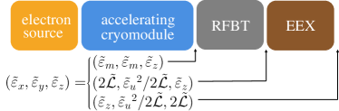
A high-level block diagram of the proposed approach to realizing emittance partition consistent with LC requirements appears in Fig. 1. In a first stage, the electron beam is emitted from a cathode immersed in an axial magnetic field provided by a solenoidal field resulting in a “magnetized” beam downstream of the magnetic-field region. The corresponding initial beam matrix is [5, 18]
| (7) |
where represent the uncorrelated beam matrix, and the matrix represents the fringe field experienced by the bunch as it exits the solenoidal field [5]
| (14) |
where . In the r.h.s. of Eq. 7 the matrix is skew-symmetric simplectic matrix, , represents the beam magnetization (here , , and are respectively the electron charge, mass, and the velocity of light) which macroscopically characterizes the beam’s average canonical angular momentum (CAM). Finally, the matrix is given by
| (17) |
indicating that as the beam exits the magnetic-field region the conservation of CAM leads to a fully coupled beam with kinematical angular momentum . It should also be noted that represents the projected emittance in or .
Downstream of the electron source the beam is injected in a linac for acceleration. The acceleration is provided by cylindrical symmetric cavity which generally support a radially axisymmetric ponderomotive focusing [19] thereby not affecting the form of the beam matrix described by Eq. 7. Downstream of the linac the beam is decoupled by applying a torque using three skew-quadrupole magnets [20] described by a total transfer matrix . The final beam has an asymmetric transverse emittance partition [18] with corresponding beam matrix
| (18) |
where with being the betatron functions, measures the phase-space linear correlation and so that its determinant is . The transverse flat-beam emittances are given by [21, 18]
| (19) |
where should be understood as the uncorrelated emittance originating from the initial photocathode intrinsic emittance but also accounting for other emittance-degrading effects (space charge effects, geometric nonlinearities and aberrations associated with the external focusing represented by the term ) during acceleration and transport up to the entrance of the RFBT.
A proof of principle experiment demonstrated transverse emittance ratios [10] for a charge of 0.5 nC while a recent experiment has attained an emittance ratio of for a 1-nC bunch [22].
The second stage of the proposed photoinjector consists of exchanging the horizontal and longitudinal phase spaces using a EEX beamline. The design of such beamline was extensively discussed in, e.g., Refs [8, 9, 23]. A solution for such a EEX beamline consists of a deflecting cavity flanked by two dispersive sections. In order to ensure the transfer matrix in is 2x2-block anti-diagonal in , the deflecting voltage is related to the dispersion generated by the upstream dispersive section following , where is the deflecting strength and (with being the deflecting-mode wavelength). Under such a condition the general transfer matrix of an EEX beamline is
| (20) |
A simple implementation of an EEX beamline consists of deflecting cavity flaned by two identical dispersive section arranged as dogleg [9]. In such a case the matrix is
| (21) |
where and are respectively the horizontal and longitudinal dispersion downstream of one dogleg and its length. Such EEX beamlines have demonstrated near-ideal emittance exchange [11] and the formation of temporally-shaped beams [12, 24].
The final beam matrix downstream of the EEX is
| (22) |
where (with ) assumes the same form as the matrix introduced in Eq. 18. Consequently, the final normalized-emittance partition is
| (23) |
where following our earlier convention for emittance.
II.2 Deviations from linear transformation
The process described in the previous Section II.1 idealizes the emittance partitioning and exchange by describing the associated transform with linear transfer matrices and ignoring collective effects. In this section, we briefly review some limitations of the process and corrections that were considered for the design simulated in Section III and diagrammed in Fig. 2.
First, it should be noted that in our configuration we constrain the beam to have a low fractional energy spread before the RFBT which results in insignificant chromatic aberration and near-ideal transfer of eigenemittance to transverse emittance.
As far as the EEX is concerned one critical deviation from the matrix model discussed in the previous section comes from the thick-lens matrix of the deflecting cavity (labeled as T1-3 in Fig. 2) which introduces a coupling element between the horizontal and longitudinal DOF [8] and breaks the block anti-diagonal form of given by Eq. 20. However, the cancellation of this term was shown to be possible using an accelerating cavity operating at zero crossing [25, 26]. Consequently, accelerating cavities were introduced (H4-5 in Fig. 2) downstream of the deflecting cavities.
The beam dynamics in the EEX section is impacted by second-order effect. In Ref. [9] it was pointed out that a proper LPS chirp could mitigate second-order aberration. In our setup given the targeted vertical emittance the introduction of the chirp would have to be done with another linac module located between the RFBT and EEX as a chirp at the entrance of the RFBT would impact the small vertical emittance due to chromatic aberration in the RFBT.Given the need to minimize the final horizontal emittance, we follow the analysis detailed in Ref. [14] to understand the source of possible final horizontal-phase-space diluation. We start by considering the phase-space coordinate of an electron downstream of the first dogleg (consisting of dipole magnets B1 and B2) we have
| (24) | |||||
| (25) |
for the horizontal phase space. The longitudinal phase-space coordinates are
| (26) | |||||
| (27) |
In the latter equations, the subscript 0 indicates the coordinate upstream of B1, and the are the usual second-order aberration coefficients [27] associated with one dogleg 111The nonlinear aberrations arising from the deflecting cavity are ignored in this section for sake of simplicity. Their inclusions do not affect the discussion and overall aberration-correction method..
Finally, the horizontal coordinates after the EEX section are given by
| (28) | |||||
| (29) |
where , and are the and coordinates after second dogleg. In latter equation we neglected geometric aberrations arising from the coupling with the given the very low vertical emittance. Likewise, we ignore the and terms associated with the first dogleg since the initial correlation is small (ideally vanishing).
The and terms in the final horizontal coordinates can be minimized by imposing a large at the entrance of EEX. The rest of the second order terms related to and can be reduced with a initial correlation in and to produce a horizontal and longitudinal beam waist at the center of the TDC so the quantity , and in Eq. 28 are minimized. Finally, the coordinate downstream of B4 can be written as
| (30) | |||||
| (31) |
The previous equation is obtained by enforcing the condition required for emittance exchange.
III Numerical proof of concept for producing beam with ILC-like parameters
In this section we apply the concept devised in the previous section to the case of the ILC to produce an emittance partition similar to the one produced downstream of the ILC damping ring [6]; see Table 1. The design philosophy focuses on designing an injector capable of minimizing the beam emittance along all d.o.f’s upstream of the RFBT, and then optimizing the emittance repartitioning in the RFBT and emittance-exchange process in the EEX beamlines. Each of these steps is discussed below.
III.1 Beam generation
The conceptual design of the photoinjector beamline from the photocathode surface up to the entrance of the RFBT is diagrammed in Figure 3. The injector beamlines was modeled using the particle-in-cell beam-dynamics program impact-t [28]. The electron source consists of a -cell RF gun operating at GHz operating with a peak field on the cathode of MV/m. The downstream linac consists of five TESLA-type 9-cell superconducting RF (SRF) cavities operating at a peak field of MV/m (corresponding to an accelerating gradient MV/m consistent with ILC demonstrated requirement of MV/m [29]). The RF gun is nested in a pair of solenoidal lenses to control the beam emittance. The beamline parameters [laser spot radius, solenoid (S1 and S2) strengths and locations, field amplitude and phase of L1] were optimized to minimize the transverse uncorrelated emittance and maximize the eigenemittance ratio at the exit of the L1. To ensure a minimal longitudinal emittance and space-charge effects, we considered a spatiotemporally shaped laser pulse with uniform three-dimensional ellipsoidal intensity distribution [30, 31].
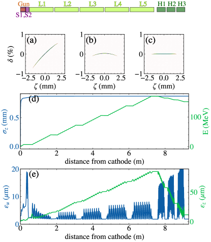
The photoemitted electron beam mirrors the laser distribution thereby prducing space-charge fields with a linear dependence on the spatial coordinate within the ellipsoidal bunch [32, 33]. The linear space-charge force mitigates emittance dilution and imparts a significant chirp in the longitudinal phase space (LPS). Additionally, the resulting bunch length [ mm; see Fig. 3(a)] leads the LPS to develop a quadratic correlation induced by the RF waveform; see Fig. 3(b). The linac cavities (L2-5) are operated off-crest to remove the linear LPS correlation after acceleration to 151 MeV; see Fig. 3(b). The 1.3-GHz linacs are followed by a 3rd-harmonic accelerating-cavity module operating at GHz to correct the quadratic correlation in the LPS and reduce the longitudinal emittance. The module comprises three SRF 3rd-harmonic cavities (H1-3) with a similar design as discussed in Ref. [34]. The cancellation of the quadratic correlation gives an 8 fold decrease in the longitudinal emittance to a final value of µm; see Fig. 3(e). The beamline parameters and resulting beam-emittance partitions are summarized in Table 2.
| parameter | symbol | value | unit |
|---|---|---|---|
| charge | Q | 3.2 | nC |
| laser pulse full (and rms) duration | 10 (2.24) | ps | |
| laser rms spot size | 1.93 | mm | |
| thermal emittance | 1.634 | m | |
| magnetic field on cathode | 226 | mT | |
| laser/gun launch phase | 222emission phase wrt to zero-crossing. | 50 | deg |
| peak E field on cathode | 60 | MV/m | |
| L2-L5 off-crest phase | 2 | deg | |
| linac peak electric field | 60 | MV/m | |
| H1-H3 off-crest phase | 178.68 | deg | |
| H1-H3 peak electric field | 34 | MV/m | |
| total beam energy | 151 | MeV | |
| longitudinal emittance | 11.78 | µm | |
| transverse eigenemittance | 6.84 | nm | |
| transverse eigenemittance | 493.4 | µm | |
| transverse uncorrelated emittance | 1.85 | µm | |
| magnetization | 246.7 | µm |
III.2 Emittance Manipulation
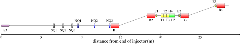
The emittance-manipulation beamline comprising the RFBT and EEX sections was simulated using elegant [35]. The simulations account for higher-order aberrations and bunch self-interaction due to coherent synchrotron radiation (CSR). The beamline is located just after the photoinjector displayed in Fig. 3, at an energy of MeV. Downstream of the injector, the magnetized beam is focused by a solenoid into RFBT sections where three skew quadrupoles remove the angular momentum of the magnetized beam and transform the magnetized beam into flat beams with emittance partition downstream of the RFBT
This emittance partition confirms that the mapping of the transverse eigenemittances listed in Table 2 to transverse emittance is near ideal (the emittance dilution associated with the mapping is 4.8%) and the longitudinal emittance is preserved (relative emittance growth of 0.3%). The flat beam is then matched into the EEX beamlines with NQ1-3 to meet the Courant-Snyder parameters requirement described in Section II.2. The condition for the correlation is not imposed as we found the contribution of the term in Eq. 28 is insignificant for our beam parameters. The EEX beamline consists of two doglegs each with dipole bending angles of , three 3.9-GHz deflecting cavities, and two 3.9-GHz accelerating cavities. The use of multiple SRF cavities is required given the demonstrated cavity performance (maximum achievable deflecting or accelerating voltage) and our requirements. Aside from canceling the thick lens effect of TDC, the accelerating cavities are also used to partially compensate for the correlated energy spread induced by CSR. Additionally, three sextupole magnets (labeled as E1-3) are inserted in the EEX beamline to correct the nonlinearities arising from the deflecting and accelerating 3.9-GHz cavities. The voltages of the TDC and third harmonic cavities, along with the strengths of the sextupole magnet, were numerically optimized to minimize the final horizontal emittance downstream of the EEX beamline. The optimized settings for cavities and magnets appear in Table 3.
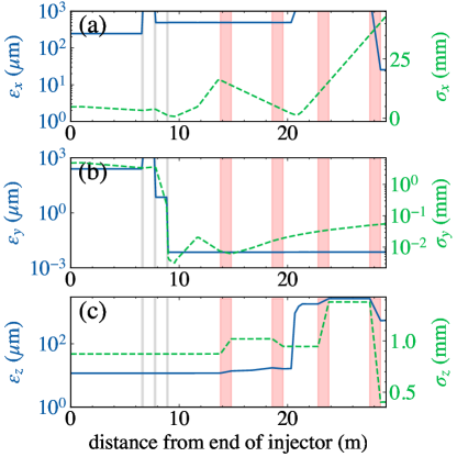
The evolution of the beam emittances along the emittance-manipulation section is presented in Fig. 4 and confirms a final emittance partition of
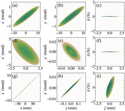
was attained corresponding to a 6D brightness pC/(µm3). This 6D brightness is a factor of higher than the one listed under “RF gun” in Table 1 most likely due to the use of a 3D ellipsoidal photocathode-laser distribution in the present work while Ref. [4] employs a uniform-cylinder laser distribution. Snapshots of the phase-space distributions at different stages of the beam generation and manipulation along the beamline appear in Fig. 5.
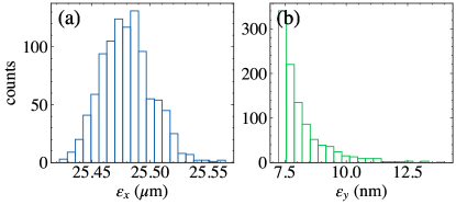
We evaluated the robustness of the proposed design and the sensitivity of the final transverse emittances to shot-to-shot jitters associated with amplitude and phase stability of the SRF cavities via start-to-end simulations. Specifically, we performed 1000 start-to-end simulations with different random realizations of the RF amplitude and phase for all the SRF cavities. The amplitude and phase values were randomly generated with a normal distribution with respective rms jitter of 0.01% (fractional deviation from nominal-amplitude settings) and 0.01 degree (for the 1.3 GHz cavities) and 0.03 deg (for the 3.9 GHz cavities). These tolerances are consistent with the performances of the low-level RF system at the European X-ray FEL [36]. These jitter studies confirm that the associated transverse-emittance fluctuations are acceptable – i.e. µm and nm; see corresponding histogram in Fig. 6.
| parameter | value | unit |
|---|---|---|
| skew quadrupole magnet SQ1 | m-1 | |
| skew quadrupole magnet SQ2 | m-1 | |
| skew quadrupole magnet SQ3 | m-1 | |
| sextupole magnet E1 | m-2 | |
| sextupole magnet E2 | m-2 | |
| sextupole magnet E3 | m-2 | |
| doglegs dispersion | -1.67 | m |
| TDC section kick strength | 6 | m-1 |
| dipole magnet B1-B4 angles | 2 | deg |
| T1 deflecting voltage | 3.72 | MV |
| T2 deflecting voltage | 3.72 | MV |
| T3 deflecting voltage | 3.66 | MV |
| H4 accelerating voltage | 5.81 | MV |
| H5 accelerating voltage | 5.91 | MV |
III.3 Spin dynamics
The present requirements from high-energy physics call for 80% spin-polarized electron beams. The / bunch charge ranges from fC to nC depending on the LC technology choice [37]. In most of the designs, the polarized electron beam is produced via photoemission from semiconductor Gallium-Arsenide (GaAs) photocathodes placed in a DC-gun [38]. Operation of a Gallium-Arsenide (GaAs) photocathodes in an RF gun remains a challenge and has been the subject of intense research [39, 40, 41]. The photoinjector is expected to produce a longitudinally spin-polarized electron beam with most of the electrons’ spin vector .
The evolution of the spin in an externally-applied magnetic field can be described by the classical spin vector under the action of a semiclassical spin precession vector via the BMT equation [42]
| (32) |
with,
| (33) | |||||
where is anomalous magnetic moment and with being the velocity.
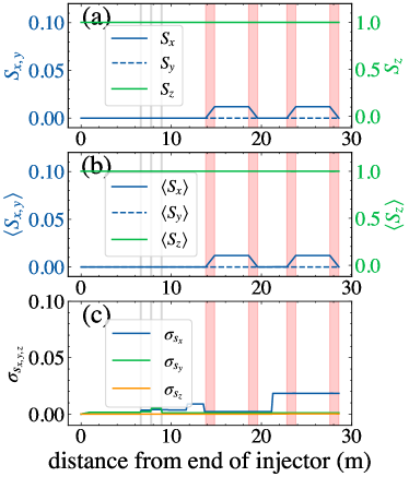
The spin dynamics of the particle distribution was investigated with the beam-dynamics program bmad [43] which implements a Romberg integration of the spin rotation matrix. Figure 7 presents the evolution of spin-vector components through the RFBT and EEX sections shown in Fig. 2. The initial conditions are such that the beam is 100% longitudinally spin-polarized . The simulation indicate that the RFBT does not impact the spin (no depolarization is observed) while the EEX beamline yield a small depolarization with final mean and RMS longitudinal spin values being respectively and . confirming that the longitudinal depolarization is insignificant .
III.4 Enhanced Luminosity
The noted reduction in longitudinal emittance combined with longitudinal bunch compression could further enhance the luminosity given the scaling ; see Eq. 2. In addition to improving luminosity, colliding short bunches also mitigate beamstrahlung-radiation losses thereby allowing the particles to experience extreme electromagnetic fields to probe non-perturbative quantum-electrodynamics effects [44]. The photoinjector described in Sec. III.1 produces a final LPS with bunch length µm; see Fig. 8(a). Further accelerating the beam to 5 GeV [see Fig. 8(b)] and considering a single-stage bunch compressor (as implemented in the nominal ILC design downstream of the DR [45]) can reduce the bunch length to µm; see Fig. 8(c,d).
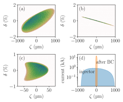
The simulations presented in Fig. 8 were performed with a 1D single-particle model of the longitudinal beam dynamics. In the model, the linac accelerates the beam from 151 MeV to 5 GeV. The linac runs off-crest to impart the required correlated energy spread for maximum compression in a downstream bunch compressor. The bunch compressor is modeled by its longitudinal dispersion cm (in our convention corresponds to a chicane-like compressor).
IV conclusion
In summary, we demonstrated a beamline composed of two cascaded cross-plane manipulations that could produce an electron beam with a final transverse-emittance partition comparable to the one attained downstream of the damping ring in the proposed ILC design. Additionally, our method produces electron bunches with brightness orders of magnitude higher than the ILC design. The enhanced brightness could further increase the luminosity by producing shorter bunches at the interaction point. Finally, the proposed scheme presents a substantial cost and complexity reduction compared to a damping ring. Although our focused was on demonstrating the application of the scheme to ILC-like parameters, the concept also be optimized for other LC designs.
Yet, the integration of the proposed technique in future LC designs is contingent on the successful generation of spin-polarized beams from RF guns. Likewise, the method could also apply to positron beams pending the availability of low-emittance positron sources such as, e.g., recently proposed based on an electrostatic trap [46], or relying on bremsstrahlung by impinging electron beams on thin targets [47].
Ultimately, the emittance-manipulation method discussed in this paper will require a vigorous R&D program on sources of bright spin-polarized electron and positron beams to be deployed in a future LC design. Two complementary experiments aimed at testing the proposed concepts are currently in preparation at the Argonne Wakefield Accelerator (AWA) [22] and the Superconducting Test Facility (STF) at the High Energy Accelerator Research Organization (KEK) [48].
V acknowledgements
We thank Dr. Eliana Gianfelice-Wendt (FNAL) for her suggestions regarding spin-dynamics simulations along with Drs. Chris Mayes (SLAC) and David Sagan (Cornell University) for their help with the spin-tracking feature of bmad. We appreciate discussions with Dr. Zachary Liptak (Hiroshima University). PP is grateful to Dr. Spencer Gessner (SLAC) for sharing a draft manuscript [46] on bright positron sources. This research was initiated in the framework of the “US-DOE-Japan cooperation in High-Energy Physics” program. This work was supported by the U.S. Department of Energy (DOE), Office of Science, under award No. DE-SC0018656 with Northern Illinois University (NIU) and contract No. DE-AC02-06CH11357 with Argonne National Laboratory (ANL).
The computing resources used for this research were provided on bebop, a high-performance computing cluster operated by the Laboratory Computing Resource Center (LCRC) at ANL.
References
- Ellis and Wilson [2001] J. Ellis and I. Wilson, New physics with the compact linear collider, Nature 409, 431 (2001).
- Dugan [2004] G. Dugan, Advanced accelerator system requirements for future linear colliders, AIP Conference Proceedings 737, 29 (2004).
- Yokoya [2001] K. Yokoya, Beam-beam interaction in linear collider, AIP Conference Proceedings 592, 185 (2001).
- Krasilnikov et al. [2012] M. Krasilnikov, F. Stephan, G. Asova, H.-J. Grabosch, M. Groß, L. Hakobyan, I. Isaev, Y. Ivanisenko, L. Jachmann, M. Khojoyan, G. Klemz, W. Köhler, M. Mahgoub, D. Malyutin, M. Nozdrin, A. Oppelt, M. Otevrel, B. Petrosyan, S. Rimjaem, A. Shapovalov, G. Vashchenko, S. Weidinger, R. Wenndorff, K. Flöttmann, M. Hoffmann, S. Lederer, H. Schlarb, S. Schreiber, I. Templin, I. Will, V. Paramonov, and D. Richter, Experimentally minimized beam emittance from an -band photoinjector, Phys. Rev. ST Accel. Beams 15, 100701 (2012).
- Brinkmann et al. [2001] R. Brinkmann, Y. Derbenev, and K. Flöttmann, A low emittance, flat-beam electron source for linear colliders, Phys. Rev. ST Accel. Beams 4, 053501 (2001).
- Phinney et al. [2007] N. Phinney, N. Toge, and N. Walker, ILC reference design report volume 3 - accelerator (2007).
- CLIC et al. [2018] T. CLIC, T. Charles, P. Giansiracusa, T. Lucas, R. Rassool, M. Volpi, C. Balazs, K. Afanaciev, V. Makarenko, A. Patapenka, et al., The compact linear collider (clic)-2018 summary report, arXiv preprint arXiv:1812.06018 (2018).
- Cornacchia and Emma [2002] M. Cornacchia and P. Emma, Transverse to longitudinal emittance exchange, Phys. Rev. ST Accel. Beams 5, 084001 (2002).
- Emma et al. [2006] P. Emma, Z. Huang, K.-J. Kim, and P. Piot, Transverse-to-longitudinal emittance exchange to improve performance of high-gain free-electron lasers, Phys. Rev. ST Accel. Beams 9, 100702 (2006).
- Piot et al. [2006] P. Piot, Y.-E. Sun, and K.-J. Kim, Photoinjector generation of a flat electron beam with transverse emittance ratio of 100, Phys. Rev. ST Accel. Beams 9, 031001 (2006).
- Ruan et al. [2011] J. Ruan, A. S. Johnson, A. H. Lumpkin, R. Thurman-Keup, H. Edwards, R. P. Fliller, T. W. Koeth, and Y.-E. Sun, First observation of the exchange of transverse and longitudinal emittances, Phys. Rev. Lett. 106, 244801 (2011).
- Sun et al. [2010] Y.-E. Sun, P. Piot, A. Johnson, A. H. Lumpkin, T. J. Maxwell, J. Ruan, and R. Thurman-Keup, Tunable subpicosecond electron-bunch-train generation using a transverse-to-longitudinal phase-space exchange technique, Phys. Rev. Lett. 105, 234801 (2010).
- Groening et al. [2014] L. Groening, M. Maier, C. Xiao, L. Dahl, P. Gerhard, O. K. Kester, S. Mickat, H. Vormann, M. Vossberg, and M. Chung, Experimental proof of adjustable single-knob ion beam emittance partitioning, Phys. Rev. Lett. 113, 264802 (2014).
- Ha et al. [2016] G. Ha, M. Cho, W. Gai, K.-J. Kim, W. Namkung, and J. Power, Perturbation-minimized triangular bunch for high-transformer ratio using a double dogleg emittance exchange beam line, Phys. Rev. Accel. Beams 19, 121301 (2016).
- Yampolsky et al. [2010] N. Yampolsky, B. Carlsten, R. Ryne, K. Bishofberger, S. Russell, and A. Dragt, Controlling electron-beam emittance partitioning for future x-ray light sources (2010), arXiv:1010.1558 [physics.acc-ph] .
- Carlsten et al. [2011] B. E. Carlsten, K. A. Bishofberger, L. D. Duffy, S. J. Russell, R. D. Ryne, N. A. Yampolsky, and A. J. Dragt, Arbitrary emittance partitioning between any two dimensions for electron beams, Phys. Rev. ST Accel. Beams 14, 050706 (2011).
- Duffy and Dragt [2016] L. D. Duffy and A. J. Dragt, Chapter one - utilizing the eigen-emittance concept for bright electron beams, in Advances in Imaging and Electron Physics, Vol. 193, edited by P. W. Hawkes (Elsevier, 2016) pp. 1–44.
- Kim [2003] K.-J. Kim, Round-to-flat transformation of angular-momentum-dominated beams, Phys. Rev. ST Accel. Beams 6, 104002 (2003).
- Rosenzweig and Serafini [1994] J. Rosenzweig and L. Serafini, Transverse particle motion in radio-frequency linear accelerators, Phys. Rev. E 49, 1599 (1994).
- Sun et al. [2004] Y. Sun, P. Piot, K.-J. Kim, N. Barov, S. Lidia, J. Santucci, R. Tikhoplav, and J. Wennerberg, Generation of angular-momentum-dominated electron beams from a photoinjector, Phys. Rev. ST Accel. Beams 7, 123501 (2004).
- Burov et al. [2002] A. Burov, S. Nagaitsev, and Y. Derbenev, Circular modes, beam adapters, and their applications in beam optics, Phys. Rev. E 66, 016503 (2002).
- Xu et al. [2022] T. Xu, D. S. Doran, W. Liu, P. Piot, J. G. Power, C. Whiteford, and E. Wisniewski, Demonstration of eigen-to-projected emittance mapping for an ellipsoidal electron bunch, Phys. Rev. Accel. Beams 25, 044001 (2022).
- Nanni and Graves [2015] E. A. Nanni and W. S. Graves, Aberration corrected emittance exchange, Phys. Rev. ST Accel. Beams 18, 084401 (2015).
- Ha et al. [2017] G. Ha, M. H. Cho, W. Namkung, J. G. Power, D. S. Doran, E. E. Wisniewski, M. Conde, W. Gai, W. Liu, C. Whiteford, Q. Gao, K.-J. Kim, A. Zholents, Y.-E. Sun, C. Jing, and P. Piot, Precision control of the electron longitudinal bunch shape using an emittance-exchange beam line, Phys. Rev. Lett. 118, 104801 (2017).
- Zholents and Zolotorev [2011] A. A. Zholents and M. S. Zolotorev, A new type of bunch compressor and seeding of short wave length coherent radiation, Tech. Rep. ANL/APS/LS-327 (Argonne National Laboratory, 2011).
- Xiang and Chao [2011] D. Xiang and A. Chao, Emittance and phase space exchange for advanced beam manipulation and diagnostics, Phys. Rev. ST Accel. Beams 14, 114001 (2011).
- Brown [1968] K. L. Brown, A First- and Second-Order Matrix Theory for the Design of Beam Transport Systems and Charged Particle Spectrometers, in Advances in Particle Physics, Volume I, edited by R. L. Cool and R. E. Marshak (1968) p. 71, also available as SLAC technical report SLAC-R-075, SLAC-75.
- Qiang et al. [2006] J. Qiang, S. Lidia, R. D. Ryne, and C. Limborg-Deprey, Three-dimensional quasistatic model for high brightness beam dynamics simulation, Phys. Rev. ST Accel. Beams 9, 044204 (2006).
- Broemmelsiek et al. [2018] D. Broemmelsiek, B. Chase, D. Edstrom, E. Harms, J. Leibfritz, S. Nagaitsev, Y. Pischalnikov, A. Romanov, J. Ruan, W. Schappert, V. Shiltsev, R. Thurman-Keup, and A. Valishev, Record high-gradient SRF beam acceleration at fermilab, New Journal of Physics 20, 113018 (2018).
- Li and Lewellen [2008] Y. Li and J. W. Lewellen, Generating a quasiellipsoidal electron beam by 3D laser-pulse shaping, Phys. Rev. Lett. 100, 074801 (2008).
- Li et al. [2009] Y. Li, S. Chemerisov, and J. Lewellen, Laser pulse shaping for generating uniform three-dimensional ellipsoidal electron beams, Phys. Rev. ST Accel. Beams 12, 020702 (2009).
- Lapostolle [1965] P. M. Lapostolle, Effets de la charge d’espace dans un accélérateur linéaire à protons, Tech. Rep. CERN-AR-Int-SG-65-15 (CERN, Geneva, 1965).
- Luiten et al. [2004] O. J. Luiten, S. B. van der Geer, M. J. de Loos, F. B. Kiewiet, and M. J. van der Wiel, How to realize uniform three-dimensional ellipsoidal electron bunches, Phys. Rev. Lett. 93, 094802 (2004).
- Bertucci et al. [2019] M. Bertucci, A. Bignami, A. Bosotti, P. Michelato, L. Monaco, C. Pagani, R. Paparella, D. Sertore, C. Maiano, P. Pierini, and J. Chen, Performance analysis of the European X-ray Free Electron Laser 3.9 GHz superconducting cavities, Phys. Rev. Accel. Beams 22, 082002 (2019).
- Borland [2000] M. Borland, ELEGANT: A Flexible SDDS-Compliant Code for Accelerator Simulation, in 6th International Computational Accelerator Physics Conference (ICAP 2000) (2000).
- Omet et al. [2018] M. Omet et al., LLRF Operation and Performance at the European XFEL, in Proc. 9th International Particle Accelerator Conference (IPAC’18), Vancouver, BC, Canada, April 29-May 4, 2018, International Particle Accelerator Conference No. 9 (JACoW Publishing, Geneva, Switzerland, 2018) pp. 1934–1936, https://doi.org/10.18429/JACoW-IPAC2018-WEPAF051.
- ALEGRO Collaboration [2019] ALEGRO Collaboration, Towards an advanced linear international collider (2019).
- Sinclair et al. [2007] C. K. Sinclair, P. A. Adderley, B. M. Dunham, J. C. Hansknecht, P. Hartmann, M. Poelker, J. S. Price, P. M. Rutt, W. J. Schneider, and M. Steigerwald, Development of a high average current polarized electron source with long cathode operational lifetime, Phys. Rev. ST Accel. Beams 10, 023501 (2007).
- Aulenbacher et al. [1996] K. Aulenbacher, G. Suberlucq, H. Tang, J. Sheppard, G. A. Mulhollan, J. P. Delahaye, J. Madsen, J. E. Clendenin, R. Bossart, and H. Braun, RF guns and the production of polarized electrons, Tech. Rep. (CERN, Geneva, 1996).
- Aleksandrov et al. [1998] A. V. Aleksandrov, E. S. Konstntinov, P. V. Logatchev, A. A. Starostenko, and A. V. Novokhatskii, High Power Test of GaAs Photocathode in RF Gun, in 6th European Particle Accelerator Conference, Stockholm, Sweden (EPAC98) (1998) pp. 1450–1452.
- Fliller et al. [2005] R. Fliller, T. Anderson, H. Edwards, H. Bluem, T. Schultheiss, C. Sinclair, and M. Huening, Progress on using NEA cathodes in an rf gun, in Proceedings of the 2005 Particle Accelerator Conference (2005) pp. 2708–2710.
- Bargmann et al. [1959] V. Bargmann, L. Michel, and V. L. Telegdi, Precession of the polarization of particles moving in a homogeneous electromagnetic field, Phys. Rev. Lett. 2, 435 (1959).
- Sagan [2006] D. Sagan, BMAD: A relativistic charged particle simulation library, Computational accelerator physics. Proceedings, 8th International Conference, ICAP 2004, St. Petersburg, Russia, June 29-July 2, 2004, Nucl. Instrum. Meth. A558, 356 (2006), proceedings of the 8th International Computational Accelerator Physics Conference.
- Yakimenko et al. [2019] V. Yakimenko, S. Meuren, F. Del Gaudio, C. Baumann, A. Fedotov, F. Fiuza, T. Grismayer, M. J. Hogan, A. Pukhov, L. O. Silva, and G. White, Prospect of studying nonperturbative QED with beam-beam collisions, Phys. Rev. Lett. 122, 190404 (2019).
- Latina and Solyak [2010] A. Latina and N. Solyak, Single-Stage Bunch Compressor for ILC-SB2009, Conf. Proc. C 100523, THPE042 (2010).
- Hessami and Gessner [2022] R. Hessami and S. Gessner, A Compact Source of Positron Beams with Small Thermal Emittance, Tech. Rep. (SLAC, Menlo Park, CA, 2022) to be published (private communication with S. Gessner).
- Abbott et al. [2016] D. Abbott, P. Adderley, A. Adeyemi, P. Aguilera, M. Ali, H. Areti, M. Baylac, J. Benesch, G. Bosson, B. Cade, A. Camsonne, L. S. Cardman, J. Clark, P. Cole, S. Covert, C. Cuevas, O. Dadoun, D. Dale, H. Dong, J. Dumas, E. Fanchini, T. Forest, E. Forman, A. Freyberger, E. Froidefond, S. Golge, J. Grames, P. Guèye, J. Hansknecht, P. Harrell, J. Hoskins, C. Hyde, B. Josey, R. Kazimi, Y. Kim, D. Machie, K. Mahoney, R. Mammei, M. Marton, J. McCarter, M. McCaughan, M. McHugh, D. McNulty, K. E. Mesick, T. Michaelides, R. Michaels, B. Moffit, D. Moser, C. Muñoz Camacho, J.-F. Muraz, A. Opper, M. Poelker, J.-S. Réal, L. Richardson, S. Setiniyaz, M. Stutzman, R. Suleiman, C. Tennant, C. Tsai, D. Turner, M. Ungaro, A. Variola, E. Voutier, Y. Wang, and Y. Zhang (PEPPo Collaboration), Production of highly polarized positrons using polarized electrons at mev energies, Phys. Rev. Lett. 116, 214801 (2016).
- Kuriki et al. [2018] M. Kuriki et al., High Aspect Ratio Beam Generation with the Phase-space Rotation Technique for Linear Colliders, in 29th International Linear Accelerator Conference (2018) p. THPO005.