Combined effects of Crab Dispersion and Momentum Dispersion in Colliders with Local Crab Crossing Scheme
Abstract
In this paper, we present the effects of linear transverse-longitudinal coupling on beam size at Interaction Point (IP) of a collider with local crab crossing scheme, when time dependent transverse deflection (crab kicks) and dispersive orbit intertwine near IP. The analytic propagation formula and the closed orbit form of the crab dispersion and momentum dispersion are derived. The non-zero momentum dispersion at crab cavities and the non-ideal phase from crab cavities to IP are detailed with the derived propagation formula to predict the beam size distortion at IP with or without the beam-beam interaction. The linear results are compared with nonlinear simulation using the weak-strong beam-beam code.
pacs:
29.27.BdI Introduction
A large crossing angle in the interaction region (IR) is necessary for fast separation of two colliding beams in ring-ring type colliders to achieve high collision rates, IR background minimization, and overall detector component and IR magnet arrangements. Crab cavities, first proposed for linear colliders Palmer (1988), can compensate for the geometrical luminosity loss induced by crossing angle. This idea was later expanded to include circular colliders Oide and Yokoya (1989).
The crab cavity generates a transverse kick, depending on the longitudinal coordinate of a particle. Due to symplecticity, the particle always receives an energy kick from the crab cavity as function of transverse offset simultaneously, as shown in Eq. (1).
| (1) | ||||
where and are horizontal and energy kick from the crab cavity, is the kick strength normalized by the momentum of the reference particle, and are the wave number and synchronous phase of the crab cavity.
In crab crossing scheme, both colliding beams are tilted by half crossing angle in plane to restore the head-on collision. There are two configurations to accomplish this: global or local schemes. In a global scheme, the crab cavity is placed at a particular location and the horizontal and longitudinal dynamics is coupled all over the ring. In a local scheme, a pair of crab cavities are installed at both sides of the IP. The upstream crab cavity tilts the beam in plane, and the downstream crab cavity rotates the beam back. In the rest of the rings, both planes stay unaffected.
The global scheme was first successfully implemented at the KEKB-factory Abe et al. (2007), where a world record luminosity of was obtained. The local scheme was also demonstrated for the hadron beam in CERN’s Super Proton Synchrotron (SPS) Calaga et al. (2021). The Electron Ion Collider (EIC) also adopts the local scheme to achieve the desired luminosity () Beebe-Wang et al. (2021). A schematic of the local crabbing compensation scheme is shown in Fig. 1 where two sets of crab cavities are placed on both sides of IP for each ring.
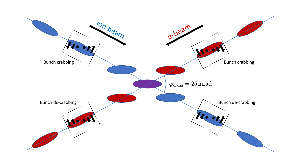
The single crab cavity dynamics in the global crabbing scheme has been studied in detail. In the absence of longitudinal motion, the linear effect of crab cavities on the closed orbit is described by the concept of dependent dispersion Sun et al. (2010), which is referred as the crab dispersion throughout this study. The linear transverse and longitudinal coupled motion due to crab cavities is analyzed through the transfer matrix in Huang (2016). The synchro-betatron stop bands due to a single crab cavity are calculated in Hoffstaetter and Chao (2004). The impact on the luminosity or the dynamical aperture is discussed in Sun et al. (2009); Funakoshi (2014).
However, the crab cavity voltage in the global scheme depends on the linear beam optics which is distorted by the beam-beam interaction. The crab dispersion all over the ring excites various synchro-betatron resonances. From KEKB operation experiences, the global scheme may be sensitive to the chromatic coupling and machine errors Funakoshi (2014). These can be avoided or mitigated in a local crabbing scheme as the crab dispersion is constrained within IR.
In the ideal local crabbing scheme, the two crab cavities, located at the location with the betatron phase advance of from IP, create desired crab dispersion "bump" between them. The crab dispersion outside the crab cavity pair vanishes. Under this ideal assumption, the nonlinear dependence from RF curvature and its impact of beam dynamics is described in Xu et al. (2021).
On the other hand, non-ideal crab-crossing setups also impact the dynamics of the colliding beams. The imperfections include the presence of dispersion at crab cavities which are first discussed in Chin (1990), and unmatched betatron phase advance between the crab cavity pair. They break the closure of the crab dispersion bump and may cause degradation of beam quality and the luminosity. We present a theoretical treatment for the interplay of momentum and crab dispersion with these imperfections, then verify the predictions with the presence of the beam-beam effect in weak-strong simulations.
This paper is organized as follows. Section II extends the concept of crab dispersion and momentum dispersion to the 6-D phase space. Section III applies the theory to explain the effects of non-zero momentum dispersion at crab cavities, and non-ideal phase advance from crab cavities to IP. Section IV shows the results of combining the momentum/crab dispersion effects with beam-beam effect in a weak-strong simulation. The conclusion is given in Sec. V.
II Crab dispersion and momentum dispersion
When the transverse coordinates ,,, and are coupled with the longitudinal offset as well as the relative momentum deviation , neither nor is constant. In consequence, the regular momentum dispersion is no longer well defined. We can instead define it as follows.
Let be a canonical transformation
| (2) |
where the superscript "T" denotes the transformation of a vector or a matrix. In the new phase space of , the longitudinal and transverse motion is decoupled. Then the momentum dispersion and the crab dispersion are defined as
| (3) |
where is the abbreviation of . and are connected by the longitudinal oscillation. As a result, the two kinds of dispersion are also interchangeable.
When the crab dispersion is not present, the transformation is well known Chao (2002)
| (4) |
where is the 4-by-4 symplectic form matrix
| (5) |
Similarly, the transformation of the crab dispersion is
| (6) |
When both kinds of dispersion are present, we can make a succession of the two canonical transformations Eq. (4) and Eq. (6),
| (7) | ||||
Substituting it back into Eq. (2), it is straightforward to check that the transformation in Eq. (7) accommodates the definition in Eq. (3),
| (8) |
where is the 4-by-4 block of .
The transformation also holds true for the definition in Eq. (3). However, is a better choice from the viewpoint of beam-beam study. From Hirata Hirata (1995), the linear map for the Lorentz boost in the crab crossing scheme is
| (9) |
where is the half crossing angle, and the approximation is used. The linear Lorentz boost is literally a crab transformation with . To provide an effective head-on collision, the crab dispersion and the momentum dispersion are found to be
| (10) |
where the superscript symbol "*" denotes IP. The property is used in Eq. (10).
The linear motion through a section can be expressed via the 6-by-6 transfer matrix . In the phase space of , the transfer matrix will be
| (11) |
where points and are the entrance and the exit of this section. According to the definition, the matrix is block diagonalized, i.e.
| (12) | ||||||
where , and are the matrix elements of at th row, th column.
There are free variables in . In the meantime, the number of independent constraints in Eq. (12) is also . In principle, and are determined by Eq. (11) and Eq. (12). The propagation of the crab dispersion and momentum dispersion can be resolved.
When the particle travels through a momentum dispersing section without any crab cavities or RF cavities, the 6-by-6 transfer matrix will be
| (13) |
where is the 4-by-4 block, and is the momentum dispersion generator. The symplectic condition requires
| (14) |
The block diagonalized matrix has a form of
| (15) |
with the symplectic constraint
| (16) |
Substituting Eq. (7), Eq. (13) and Eq. (15) into Eq. (11), it follows that
| (17) |
When , the propagation turns into
| (18) |
which is the same as the normal dispersion propagation.
When the particle passes by a cavity-like element, the linear transfer matrix is
| (19) |
with the symplectic constraint
| (20) |
where is also the 4-by-4 block, and is the crab dispersion generator.
The block diagonalized matrix is
| (21) |
with the symplectic constraint
| (22) |
Substituting Eq. (7), Eq. (19) and Eq. (21) into Eq. (11), it follows that
| (23) |
When , the propagation turns into
| (24) |
Eq. (13) and Eq. (19) include most common accelerator components in a real machine. For a one-turn map in which both momentum dispersion generator and crab dispersion generator are present, the closed orbit condition is imposed on the two dispersion functions,
| (25) |
This fixed point problem can be resolved with the help of Edwards-Teng approach Edwards and Teng (1973).
To use the Edwards-Teng approach, the discussion is limited within the 4D phase space . A general 4-by-4 transfer matrix in terms of 2-by-2 blocks is
| (26) |
Following Sagan and Rubin (1999), is block diagonalized by
| (27) |
with
| (28) |
where are 2-by-2 blocks, the symplectic conjugate of , and given by
| (29) |
where "det" means taking the determinant. This paper does not include the concrete formula of , which the reader can find in Sagan and Rubin (1999).
With the closed orbit condition, the Eq. (11) turns into
| (30) |
Comparing it with Eq. (27), is related to by a longitudinal scaling transformation, i.e.
| (31) |
where is a 2-by-2 matrix. From Eq. (31), the two kinds of closed orbit dispersion are
| (32) |
and the matrix follows
| (33) |
The crab dispersion and the momentum dispersion at any point are related to the closed orbit form in Eq. (25) by the propagation formulas Eq. (17) and Eq. (23). Eq. (7) presents a technique to decouple the transverse and the longitudinal phase space following acknowledgment of the two types of dispersion.
III Applications without beam-beam
In this section, the subscript "b" denotes before IP, whereas the subscript "a" denotes after IP. Without loss of generality, our discussion focuses in the 4D phase space . The propagation of the crab dispersion and the momentum dispersion don’t involve the vertical plane. The lattice is assumed symmetrical around IP. The Crab Cavity Before IP (CCB) and the Crab Cavity After IP (CCA) are placed at , as shown in Fig. 2.

III.1 Non-zero momentum dispersion at crab cavities
When the crab cavities are turned off, the momentum dispersion vanishes at IP. Let the momentum dispersion at CCB be . Then the transfer matrix from CCB to IP is
| (34) |
where , and are the horizontal beta functions at crab cavities and IP. From the symmetry of the lattice, the momentum dispersion at CCA is , and the transfer matrix from IP to CCA is
| (35) |
The periodic transfer matrix at IP should be
| (36) | ||||
where the transfer matrix from CCA to CCB, the periodic phase advance in horizontal/longitudinal plane, the RMS bunch length, and the RMS momentum spread.
When the crab cavities are turned on, from Eq. (1) the linear transfer matrix of CCB and CCA are
| (37) |
where and are the strength of the crab cavity.
Starting with
| (38) |
after transported to CCB by , defelected by , and transported back to IP by , the crab dispersion and the momentum dispersion before collision read,
| (39) |
Expanding Eq. (39) to the first order of ,
| (40) |
The Lorentz boost in Eq. (10) will cancel the crab dispersion when . However, the momentum dispersion doesn’t vanish when or . Therefore, the horizontal coordinate will depend on the momentum spread in the head-on frame, as shown in Fig. 3.
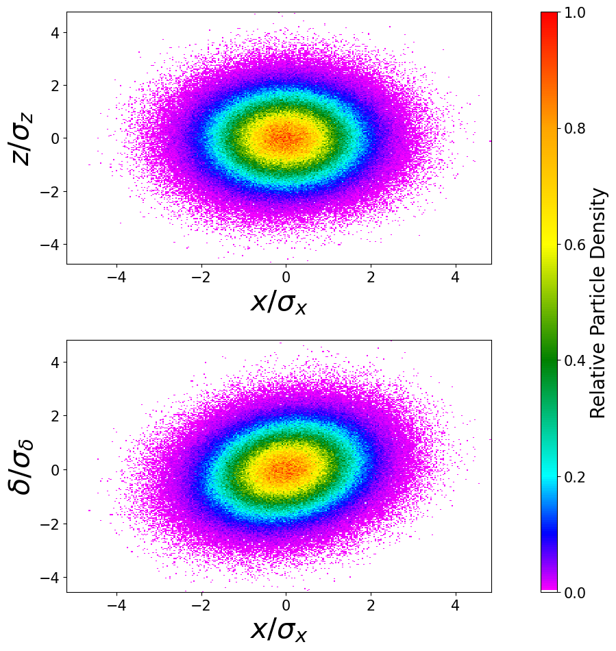
Due to the non-zero dispersion, the transverse coordinates relate to the momentum spread in the head-on frame by
| (41) |
The dispersion can then be calculated from the second order moments as
| (42) |
where denotes taking the average over the particle distribution. Figure 4 compares the dispersion calculated from the analytic formula Eq. (40) and from the beam distribution Eq. (42).

Projecting the crab dispersion and the momentum dispersion at the other side back to IP, it follows
| (43) |
Expanding Eq. (43) to the first order of ,
| (44) |
Taking both sides into consideration, the crab dispersion can be closed when
| (45) |
Then the residual momentum dispersion is
| (46) |
The leakage of the momentum dispersion will lead to the coupling between the horizontal and longitudinal plane, and it is necessary to consider the closed orbit form of the two types of distribution.
Define
| (47) |
With both crab cavities on, the periodic transfer matrix at IP is
| (48) | ||||
Following the procedure in Sagan and Rubin (1999), we define
| (49) |
and then
| (50) |
The stability criterion is
| (51) |
Similar to the betatron resonance, the sum resonance is dangerous, while the motion on difference resonance is stable. However, the longitudinal average action is usually much larger than the horizontal RMS emittance, the coupling has to be weak enough to prevent the luminosity loss,
| (52) |
From Eq. (32), the two kinds of closed orbit dispersion are
| (53) | ||||
where
| (54) |
To prevent the horizontal beam size blows up,
| (55) |
so that the constraints are given by
| (56) |
and
| (57) |
From Eq. (47), and are within the same order of magnitude. As a result, the constraint of Eq. (57) is generally satisfied. However, when is close to , even if the stability criterion Eq. (51) holds, the constraint of Eq. (56) may be broken. In other words, the leakage of momentum dispersion will result in a significant closed orbit crab dispersion, and the luminosity will be reduced hereafter.
The theory is verified by tracking. The macro particles are randomly generated at IP from the Gaussian distribution,
| (58) | ||||
The parameters are listed in Tab. 1. The working point is chosen close to the difference resonance.
| Parameter | Unit | Value |
|---|---|---|
| Horizontal size | ||
| Horizontal divergence | ||
| Longitudinal size | ||
| Momentum spread | ||
| Horizontal at IP | ||
| Horizontal at crab cavity | ||
| Crab cavity frequency | ||
| Crab cavity phase | ||
| Half crossing angle |
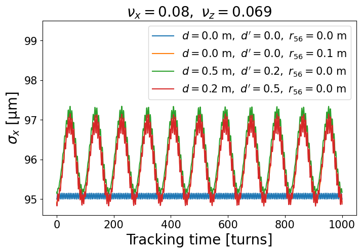
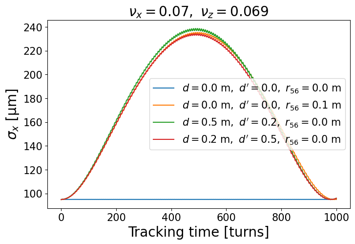
presents the beam size evolution caused by the momentum distribution leakage. In our model, all elements are linear except for the crab cavities. As a result, the beam envelope oscillates. The oscillation amplitude is determined by in Eq. (47) or to the first order, which leads to the yellow, green and red curves overlap with each other. When the horizontal tune is close to the longitudinal tune , the motion is still stable, but the envelope oscillation amplitude becomes much larger. If the coupling is weak enough, the oscillation frequency is determined by Chao (2002). The envelope oscillation will lead to the horizontal beam size blow-up when the non-linearity is present, such as the beam-beam interaction, the chromaticity, or high-order magnetic fields.
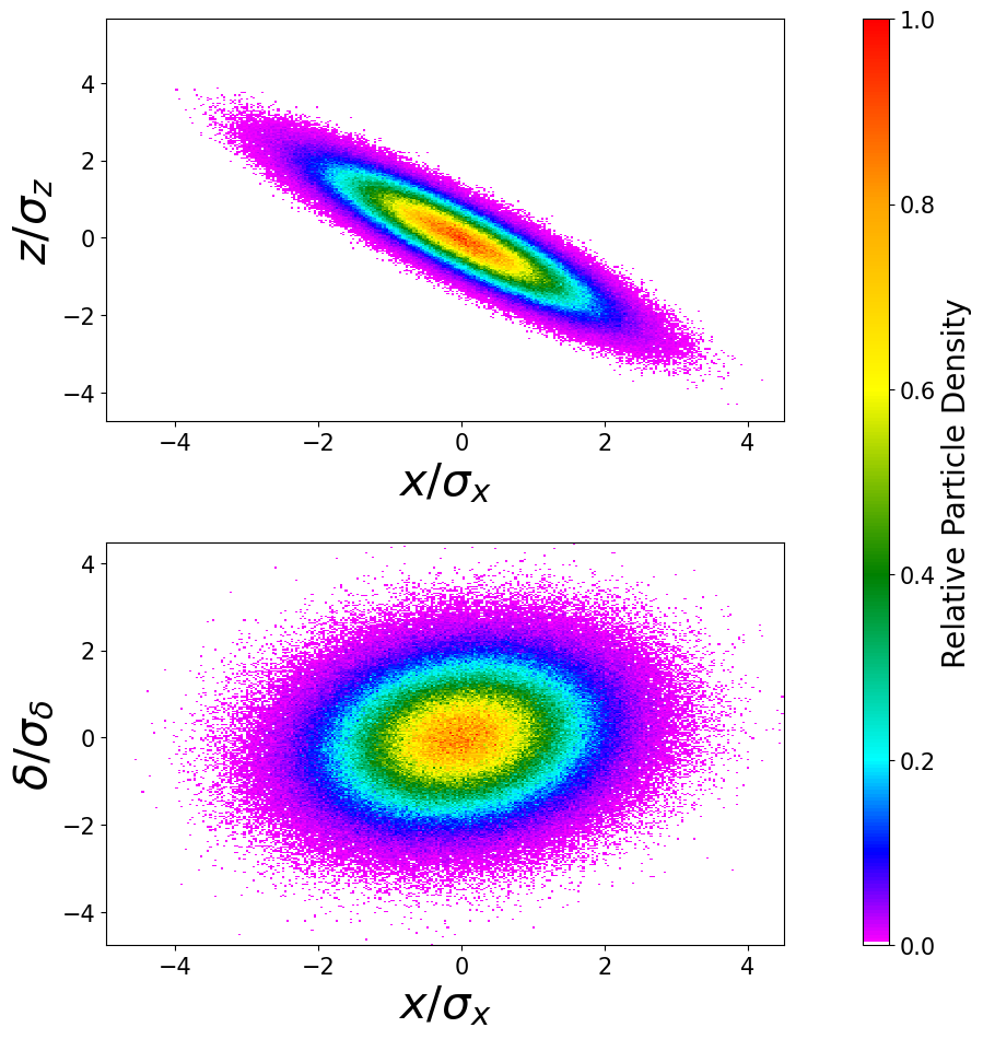
distribution in and plane at that moment. It demonstrates that the horizontal coordinate is substantially associated with the longitudinal coordinate , but weakly depending on the momentum spread . It proves that the closed orbit crab dispersion is significantly bigger than the momentum dispersion when the horizontal tune is close to the longitudinal tune.
III.2 Non-ideal phase from crab cavities to IP
The crab dispersion from the crab cavities at both sides will cancel with each other when the horizontal phase advance from the crab cavity to IP is exactly . However, this is not always true in IR design. As a result, the crab dispersion will leak out of IR.
Let be the horizontal phase from CCB to IP, and the horizontal phase from IP to CCA. The functions at both crab cavities are still assumed identical. We also omit the momentum dispersion in this section to simplify our discussion. The transfer matrix between the crab cavities and IP are given by,
| (59) | ||||
Following the same procedure in Sec. III.1, the crab dispersion before collision is,
| (60) |
when , the second term in will not be equal to . It will introduce additional synchro-betatron resonance, and will degrade the beam-beam performance.
Projecting the crab dispersion from CCA back to IP,
| (61) |
It is easy to show that the residual crab dispersion vanishes when
| (62) |
There will be a leakage of crab dispersion when the total phase deviates from .
Let
| (63) |
Then the leakage of the crab dispersion will be
| (64) |
Define
| (65) |
With the crab dispersion leakage, the periodic transfer matrix at IP is
| (66) | ||||
The stability criterion becomes
| (67) |
Assuming the longitudinal-horizontal coupling is weak enough, the two kinds of closed orbit dispersion are
| (68) |
Then a constraint is given by
| (69) |
The bunch length is usually much larger than the transverse size . Accordingly, Eq. (69) places a strict constraint on .
Figure 7
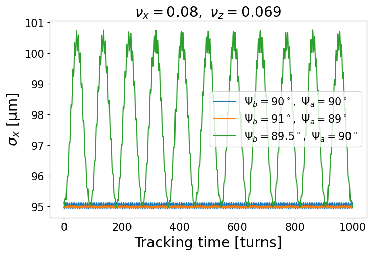
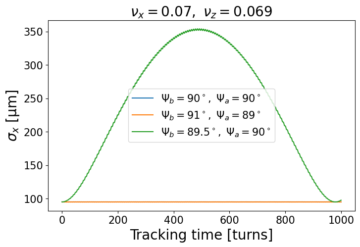
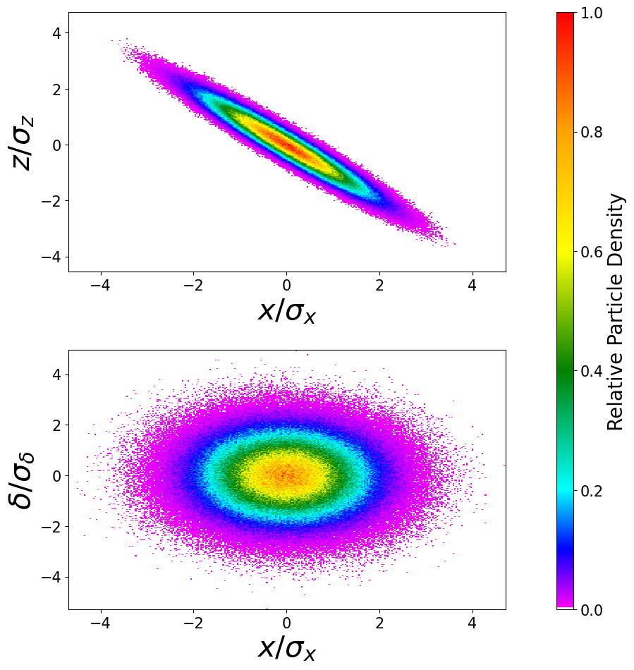
presents the beam size evolution caused by the crab distribution leakage. The simulation parameters are listed in Tab. 1. We can see that even deviation from driving a notable envelope oscillation for the tunes . Figure 8 shows the distribution in and plane when the horizontal envelope reaches maximum. It turns out that it is the closed orbit crab dispersion dominated the envelope oscillation, as predicted by Eq. (68).
IV Applications with beam-beam
The leakage of the crab dispersion and momentum dispersion will impose additional constraints on the lattice design. Weak-strong simulation is a widely used approach in beam-beam study Papaphilippou and Zimmermann (1999); Luo et al. (2012). In this part, we will investigate the influence of dispersion leakage on beam-beam performance using a self-written weak-strong code.
Table 2 presents the beam parameters used in the simulation to demonstrate the combined effects of crab dispersion and momentum dispersion.
| Parameter | Proton | Electron |
|---|---|---|
| Circumference [] | ||
| Energy [] | ||
| Particles per bunch [] | ||
| Crossing angle [] | ||
| Crab cavity frequency [] | ||
| [] | ||
| RMS emittance (H/V)[] | ||
| RMS bunch size (H/V)[] | ||
| RMS bunch length [] | ||
| RMS energy spread [] | ||
| Transverse fractional tune (H/V) | ||
| Synchrotron tune | ||
| Transverse damping time [turns] | ||
| Longitudinal damping time [turns] | ||
| Beam-beam parameter (H/V) | ||
In the simulation, the ion beam is rigid with the horizontal centroid as Xu et al. (2021)
| (70) |
where is the wave number of the crab cavities in the ion ring. A second order harmonic crab cavity is used to flatten the ion bunch in the head-on frame. The ion bunch is cut into multiple slices. Each slice is represented by a 2D Gaussian distribution in plane.
The weak electron beam are simulated by a number of macro particles. As in Sec. III.1 and Sec. III.2, both the one-turn map and the betatron map from the crab cavities to IP are described by the linear transfer matrix. The crab cavity kick follows Eq. (1). The beam-beam kick from a Gaussian distribution is calculated with the Bassetti and Erskine formula Bassetti and Erskine (1980). The effects of radiation damping and quantum excitation are represented by a lumped element Qiang et al. (2002).
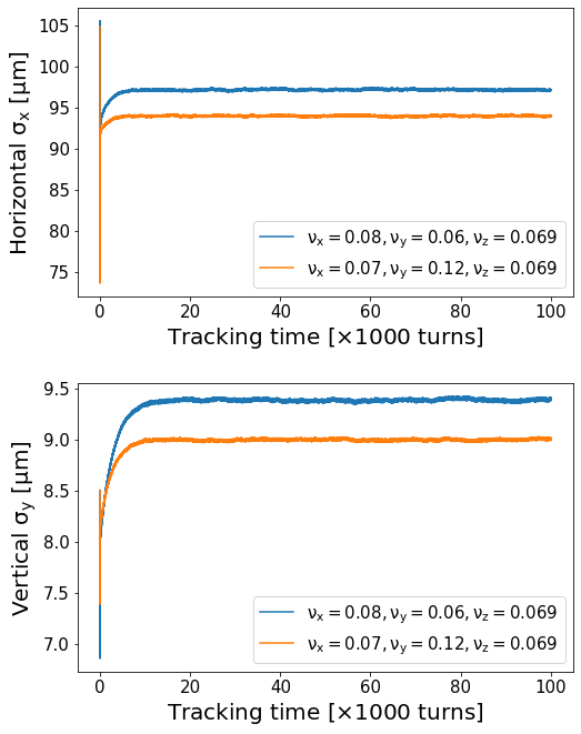
Figure 9 shows the beam size evolution without any dispersion leakage. Compared with the nominal working point in the EIC CDR, the new working point predicts smaller horizontal and vertical beam sizes after equilibrium. The horizontal size benefits from the smaller horizontal tune which reduces the dynamical under beam-beam interaction Furman (1994). The vertical size benefits from a larger difference so that the new working point moves away from the main diagonal line in the tune space. From the viewpoint of beam-beam, the new working point is a better choice.
IV.1 Non-zero momentum dispersion at crab cavities
Figure 10 presents the final beam sizes after equilibrium with different momentum dispersion and at both crab cavities. The term from CCB (IP) to IP (CCA) is set to in all simulations. Compared with the simulations without beam-beam interaction in Sec. III.1, Figure 10 shows a quite different pattern.
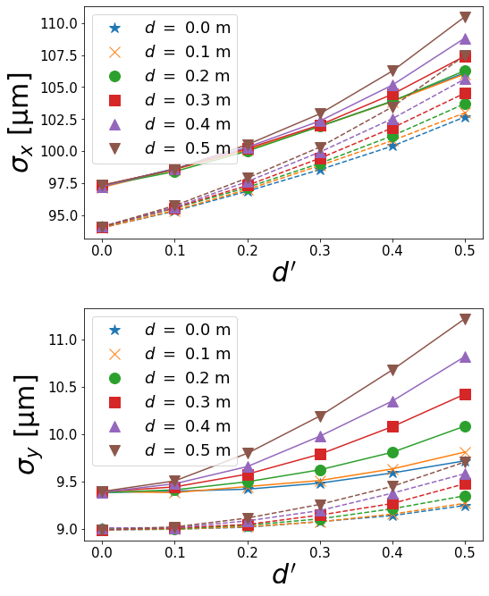
The vertical size after equilibrium is also affected due to the non-linearity from the beam-beam interaction. The horizontal blow-up is less severe even for the new working point where the horizontal tune is quite close to the longitudinal tune . The equilibrium size is mainly determined by instead of .
The reason is that the horizontal tune and function are modified by the beam-beam interaction. With the near axis approximation, the beam-beam kick can be represented by a linear quadrupole in the head-on frame,
| (71) |
where is the horizontal focal length, and can be expressed with the beam-beam parameter by
| (72) |
For simplicity, the vertical dynamics is not included here. Back into the Frenet-Serret frame, the linear beam-beam transformation is given by,
| (73) |
where is the linear Lorentz boost, as shown in Eq. (9).
Turning the crab cavities on, the total transfer matrix including the crab system and the beam-beam interaction follows
| (74) | ||||
where
| (75) |
Then the periodic transfer matrix is
| (76) |
Due to , the longitudinal-horizontal coupling is still weak. The horizontal dynamic tune and are then given by
| (77) |
Figure 11 shows the dynamical tune as a function of . For both working points, the horizontal tune with the beam-beam interaction is larger than , which is far enough away from the longitudinal tune . Therefore, the closed orbit of the momentum dispersion and crab dispersion are negligible.
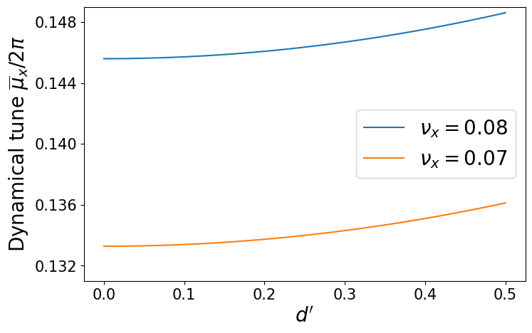
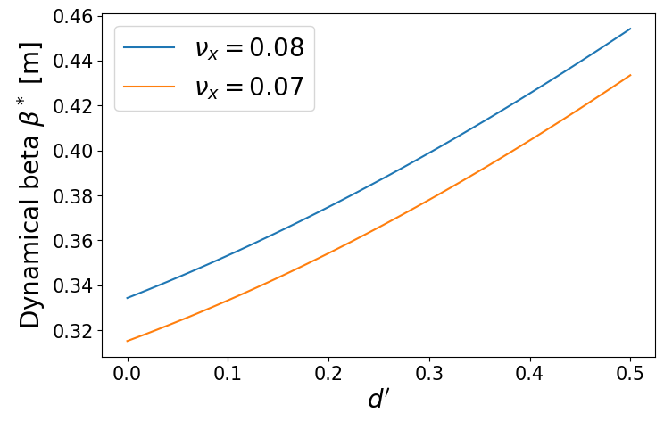
Figure 12 shows the dynamical beta as a function of . The dynamical beta increases as gets larger, which explains why the horizontal size depends mainly on instead of .
It is worthwhile to mention that the dynamical beta is not the only source of beam size growth. The non-zero momentum dispersion or at crab cavities will excite higher-order synchro-betatron resonances through the nonlinear beam-beam interaction.
In summary, from the weak-strong simulation, when the dispersion satisfy the constraints
| (78) |
the beam size growth caused by the momentum dispersion is small. The closed orbit crab dispersion or momentum dispersion without beam-beam interaction are also negligible.
IV.2 Non-ideal phase from crab cavities to IP
For symplecticity, we still omit the momentum dispersion here. Substituting Eq. (73) into Eq. (23), the crab dispersion deflected by the beam-beam kick is
| (79) |
where takes the form of Eq. (60), and the crab cavity strength is determined by Eq. (63). Because the beam-beam kick has no effect on crab dispersion, the criteria Eq. (69) still holds true, with the exception that the horizontal phase must be replaced by the dynamical phase,
| (80) |
or specifically,
| (81) |
where the dynamical phase is determined by Eq. (77), and the upper boundary is set as in Eq. (80).
Let . Then the criterion becomes numerically,
| (82) | ||||
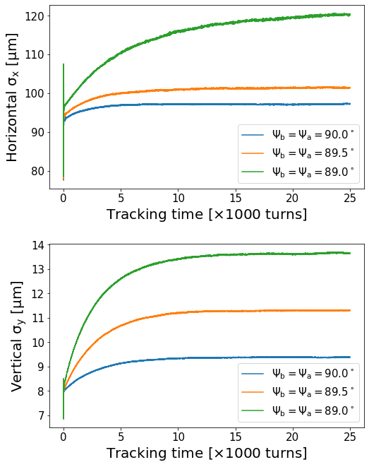
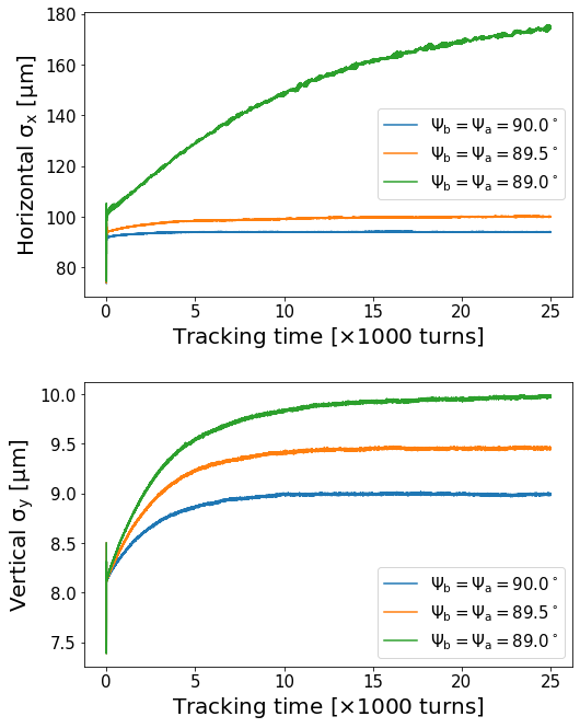
Figure 13 and Fig. 14 show the weak-strong simulation results for different at both working points. Both figures demonstrate that the constraint Eq. (82) has to be satisfied. Otherwise, the horizontal beam size will increase dramatically.
However, the constraint of Eq. (82) may be too strict to meet in reality because of the compact layout of the IR. A possible alternative is to move the crab cavities in one ring to the phase of or further.
V Conclusion
In this study, we extended the concept of crab dispersion and momentum dispersion in the presence of synchrotron motion. We derived the propagation law of the two types of dispersion traveling via common accelerator elements. Edward-Teng’s block diagonalization technique was also used to find the closed orbit form of dispersions. It enabled us to deduce the leakage of crab dispersion and momentum dispersion in the local crabbing scheme.
This paper then investigated the momentum dispersion at the crab cavities and the non-ideal phase from the crab cavities to IP. The stability criterion was derived. A lattice requirement criterion was calculated using the weak horizontal-longitudinal coupling assumption. It turned out that the beam size at IP became sensitive to the leakage of dispersions when the horizontal tune was close to the longitudinal tune. The Monte Carlo simulations were carried out to demonstrate the theoretical analysis.
The beam-beam interaction was taken into consideration in the weak-strong simulations. It showed that the momentum dispersion at crab cavities had less impact on the beam size at IP because of the beam-beam tune shift. However, the phase advance from crab cavities to IP cannot stay too far from . The numerical criteria of the electron ring lattice were given for the EIC beam parameters. The simulation results agreed with the criteria.
Acknowledgements
This work was supported by Department of Energy under Contract No. DE-AC02-98CH10886.
References
- Palmer (1988) R. Palmer, Energy scaling, crab crossing and the pair problem, Tech. Rep. (Stanford Linear Accelerator Center, 1988).
- Oide and Yokoya (1989) K. Oide and K. Yokoya, Physical Review A 40, 315 (1989).
- Abe et al. (2007) T. Abe, K. Akai, M. Akemoto, A. Akiyama, M. Arinaga, K. Ebihara, K. Egawa, A. Enomoto, J. Flanagan, S. Fukuda, et al., in 2007 IEEE Particle Accelerator Conference (PAC) (IEEE, 2007) pp. 27–31.
- Calaga et al. (2021) R. Calaga, A. Alekou, F. Antoniou, R. Appleby, L. Arnaudon, K. Artoos, G. Arduini, V. Baglin, S. Barriere, H. Bartosik, et al., Physical Review Accelerators and Beams 24, 062001 (2021).
- Beebe-Wang et al. (2021) J. Beebe-Wang et al., Electron Ion Collider Conceptual Design Report, Tech. Rep. (Brookhaven National Laboratory, 2021).
- Sun et al. (2010) Y.-P. Sun, R. Assmann, R. Tomás, F. Zimmermann, et al., Physical Review Special Topics-Accelerators and Beams 13, 031001 (2010).
- Huang (2016) X. Huang, Physical Review Accelerators and Beams 19, 024001 (2016).
- Hoffstaetter and Chao (2004) G. H. Hoffstaetter and A. W. Chao, Physical Review Special Topics-Accelerators and Beams 7, 071002 (2004).
- Sun et al. (2009) Y.-P. Sun, R. Assmann, J. Barranco, R. Tomás, T. Weiler, F. Zimmermann, R. Calaga, A. Morita, et al., Physical Review Special Topics-Accelerators and Beams 12, 101002 (2009).
- Funakoshi (2014) Y. Funakoshi, arXiv preprint arXiv:1410.4036 (2014).
- Xu et al. (2021) D. Xu, Y. Hao, Y. Luo, and J. Qiang, Physical Review Accelerators and Beams 24, 041002 (2021).
- Chin (1990) Y. H. Chin, (1990).
- Chao (2002) A. W. Chao, Lecture notes on topics in accelerator physics, Tech. Rep. (Stanford Linear Accelerator Center, Menlo Park, CA (US), 2002).
- Hirata (1995) K. Hirata, Physical review letters 74, 2228 (1995).
- Edwards and Teng (1973) D. Edwards and L. Teng, IEEE Trans. Nucl. Sci 20 (1973).
- Sagan and Rubin (1999) D. Sagan and D. Rubin, Physical Review Special Topics-Accelerators and Beams 2, 074001 (1999).
- Papaphilippou and Zimmermann (1999) Y. Papaphilippou and F. Zimmermann, Physical Review Special Topics-Accelerators and Beams 2, 104001 (1999).
- Luo et al. (2012) Y. Luo, W. Fischer, N. Abreu, X. Gu, A. Pikin, and G. Robert-Demolaize, Physical Review Special Topics-Accelerators and Beams 15, 051004 (2012).
- Bassetti and Erskine (1980) M. Bassetti and G. A. Erskine, Closed expression for the electrical field of a two-dimensional Gaussian charge, Tech. Rep. (1980).
- Qiang et al. (2002) J. Qiang, M. A. Furman, and R. D. Ryne, Parallel simulation of beam-beam interaction in high energy accelerators, Tech. Rep. (Lawrence Berkeley National Lab.(LBNL), Berkeley, CA (United States), 2002).
- Furman (1994) M. A. Furman, (1994).