Privacy-from-Birth: Protecting Sensed Data from Malicious Sensors with VERSA
Abstract
With the growing popularity of the Internet-of-Things (IoT), massive numbers of specialized devices are deployed worldwide, in many everyday settings, including homes, offices, vehicles, public spaces, and factories. Such devices usually perform sensing and/or actuation. Many of them handle sensitive and personal data. If left unprotected, ambient sensing (e.g., of temperature, motion, audio, or video) can leak very private information. At the same time, some IoT devices use low-end computing platforms with few (or no) security features.
There are many well-known techniques to secure sensed data, e.g., by authenticating communication end-points, encrypting data before transmission, and obfuscating traffic patterns. Such techniques protect sensed data from external adversaries while assuming that the sensing device itself is secure. Meanwhile, both the scale and frequency of IoT-focused attacks are growing. This prompts a natural question: how to protect sensed data even if all software on the device is compromised? Ideally, in order to achieve this, sensed data must be protected from its genesis, i.e., from the time when a physical analog quantity is converted into its digital counterpart and becomes accessible to software. We refer to this property as PfB: Privacy-from-Birth.
In this work, we formalize PfB and design Verified Remote Sensing Authorization (VERSA) – a provably secure and formally verified architecture guaranteeing that only correct execution of expected and explicitly authorized software can access and manipulate sensing interfaces, specifically, General Purpose Input/Output (GPIO), which is the usual boundary between analog and digital worlds on IoT devices. This guarantee is obtained with minimal hardware support and holds even if all device software is compromised. VERSA ensures that malware can neither gain access to sensed data on the GPIO-mapped memory nor obtain any trace thereof. VERSA is formally verified and its open-sourced implementation targets resource-constrained IoT edge devices, commonly used for sensing. Experimental results show that PfB is both achievable and affordable for such devices.
I Introduction
The impact and importance of embedded (aka IoT or “smart”) devices is hard to overestimate. They are increasingly popular and becoming pervasive in many settings: from homes and offices to public spaces and industrial facilities. Not surprisingly, they also represent increasingly attractive attack targets for exploits and malware. In particular, low-end (cheap, small, and simple) micro-controller units (MCUs) are designed with strict cost, size, and energy limitations. Thus, it is hard to offer any concrete guarantees for tasks performed by these MCUs, due to their lack of sophisticated security and privacy features, compared to higher-end computing devices, such as smartphones or general-purpose IoT controllers, e.g., Amazon Echo or Google Nest. As MCUs increasingly permeate private spaces, exploits that abuse their sensing capabilities to obtain sensitive data represent a significant privacy threat.
Over the past decade, the IoT privacy issues have been recognized and explored by the research community [1, 2, 3, 4, 5]. Many techniques (e.g., [6, 7]) were developed to secure sensor data from active attacks that impersonate users, IoT back-ends, or servers. Another research direction focused on protecting private data from passive in-network observers that intercept traffic [8, 9, 10, 11] or perform traffic analysis based on unprotected packet headers and other metadata, e.g., sizes, timings, and frequencies. However, security of sensor data on the device which originates that data has not been investigated. We consider this to be a crucial issue, since all software on the device can be compromised and leak (exfiltrate) sensed data. Whereas, aforementioned techniques assume that sensing device runs the expected benign software.
We claim that in order to solve this problem, privacy of sensed data must be ensured “from birth”. This corresponds to two requirements: (1) access to sensing interfaces must be strictly controlled, such that only authorized code is allowed to read data, (2) sensed data must be protected as soon as it is converted to digital form. Even the simplest devices (e.g., motion sensors, thermostats, and smart plugs) should be protected since prior work [12, 13, 14, 15] amply demonstrates that private – and even safety-critical – information can be inferred from sensed data. It is also well-known that even simple low-end IoT devices are subject to malware attacks. This prompts a natural question: Can privacy of sensed data be guaranteed if the device software is compromised? We refer to this guarantee as Privacy-from-Birth (PfB).
Some previous results considered potential software compromise in low-end devices and proposed methods to enable security services, such as remote verification of device software state (remote attestation) [16, 17, 18, 19, 20, 21], proofs of remote software execution [22], control- & data-flow attestation [23, 24, 25, 26, 27, 28, 29], as well as proofs of remote software updates, memory erasure, and system reset [30, 31, 32].
Regardless of their specifics, such techniques only detect of violations or compromises after the fact. In the context of PfB, that is too late since leakage of private sensed data likely already occurred. Notably, SANCUS [17] specifically discusses the problem of access control to sensor peripherals (e.g., GPIO) and proposes attestation of software accessing (or controlling access to) these peripherals. However, this only allows detection of compromised peripheral-accessing software and does not prevent illegal peripheral access.
To bridge this gap and obtain PfB, we construct the Verified Remote Sensing Authorization (VERSA) architecture. It provably prevents leakage of private sensor data even when the underlying device is software-compromised. At a high level, VERSA combines three key features: (1) Mandatory Sensing Operation Authorization, (2) Atomic Sensing Operation Execution, and (3) Data Erasure on Boot (see Section III). To attain these features, VERSA implements a minimal and formally verified hardware monitor that runs independently from (and in parallel with) the main CPU, without modifying the CPU core. We show that VERSA is an efficient and inexpensive means of guaranteeing PfB.
This work makes the following contributions:
-
•
Formulates PfB with a high-level specification of requirements, followed by a game-based formal definition of the PfB goal.
-
•
Constructs VERSA, an architecture that guarantees PfB.
-
•
Implements and deploys VERSA on a commodity low-end MCU, which demonstrates its cost-effectiveness and practicality.
-
•
Formally verifies VERSA implementation and proves security of the overall construction, hence obtaining provable security at both architectural and implementation levels. VERSA implementation and its computer proofs are publicly available in [33].
II Preliminaries
II-A Scope & MCU-based devices
This work focuses on low-end CPS/IoT/smart devices with low computing power and meager resources. These are some of the smallest and weakest devices based on low-power single-core MCUs with only a few kilobytes (KB) of program and data memory. Two prominent examples are Atmel AVR ATmega and TI MSP430: - and -bit CPUs, respectively, typically running at -MHz clock frequencies, with 64KB of addressable memory.
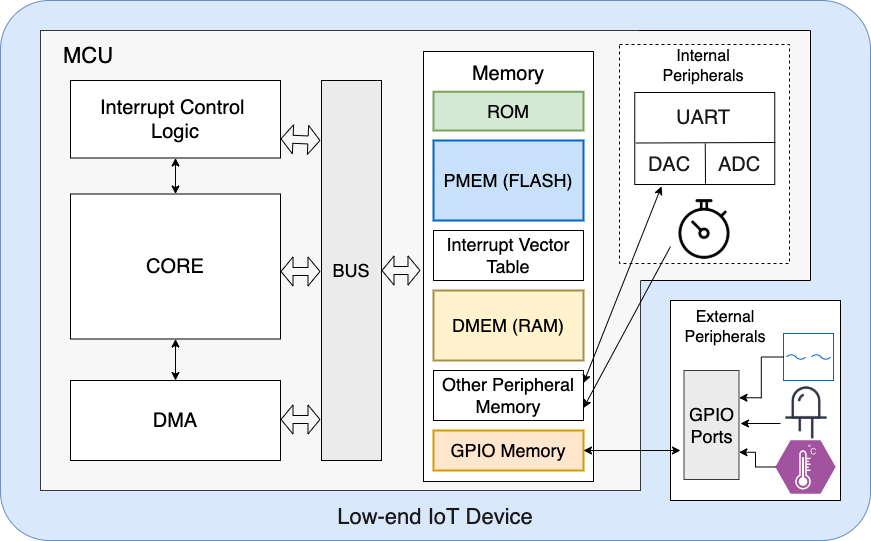
Figure 1 illustrates a generic architecture representing such MCUs. The CPU core and the Direct-Memory Access (DMA) controller access memory through a bus.111DMA is a hardware controller that can read/write to memory in parallel with the CPU. Memory can be divided into 5 logical regions: (1) Read-only memory (ROM), if present, stores critical software such as a bootloader, burnt into the device at manufacture time and not modifiable thereafter; (2) program memory (PMEM), usually realized as flash, is non-volatile and stores program instructions; (3) interrupt vector table (also in flash and often considered as part of PMEM), stores interrupt configurations; (4) data memory (DMEM), usually implemented with DRAM, is volatile and used to store program execution state, i.e., its stack and heap; and, (5) peripheral memory region (also in DRAM and often considered as a part of DMEM), contains memory-mapped I/O interfaces, i.e., addresses in the memory layout that are mapped to hardware components, e.g., timers, UART, and GPIO. In particular, GPIO are peripheral memory addresses hardwired to physical ports that interface with external circuits, e.g., analog sensors/circuits.
We note that small MCUs usually come in one of two memory architectures: Harvard and von Neumann. The former isolates PMEM and DMEM by maintaining two different buses and address spaces, while the latter keeps both PMEM and DMEM in the same address space and accessible via a single bus.
Low-end MCUs execute instructions in place, i.e., directly from flash memory. They have neither memory management units (MMUs) to support virtualization/isolation, nor memory protection units (MPUs). Therefore, privilege levels and isolation used in higher-end devices and generic enclaved execution systems (e.g., Intel SGX [34] or MIT SANCTUM [35]) are not applicable.
We believe that a PfB-agile architecture that is sufficiently inexpensive and efficient for such low-end devices can be later adapted to more powerful devices. Whereas, going in the opposite direction is more challenging. Furthermore, simpler devices are easier to model and reason about formally. Thus, we believe that they represent a natural starting point for the design and verification of a PfB-agile architecture. To this end, our prototype implementation of VERSA is integrated with MSP430, due in part to public availability of an open-source MSP430 hardware design from OpenCores [36].222Nevertheless, the generic machine model and methodology of VERSA are applicable to other low-end MCUs of the same class, e.g., Atmel AVR ATmega.
II-B GPIO & MCU Sensing
A GPIO port is a set of GPIO pins arranged and controlled together, as a group. The MCU-addressable memory for a GPIO port is physically mapped (hard-wired) to physical ports that can be connected to a variety of external circuits, such as analog sensors and actuators, as shown in Figure 1. Each GPIO pin can be set to function as either an input or output, hence called "general purpose". Input signals produced by external circuits can be obtained by the MCU software by reading from GPIO-mapped memory. Similarly, egress electric signals (high or low voltage) can be generated by the MCU software by writing (logical or ) to GPIO-mapped memory.
Remark: “GPIO-mapped memory” includes the set of all software-readable memory regions connected to external sensors. In some cases, this set may even include multiple physical memory regions for a single physical pin. For instance, if a given GPIO pin is also equipped with an Analog-to-Digital Converter (ADC), a GPIO input could be reflected on different memory regions depending on whether the ADC is active or inactive. All such regions are considered “GPIO-mapped memory” and we refer to it simply as GPIO. Using this definition, in order to access sensor data, software running on the MCU must read from GPIO.
We also note that various applications require different sensor regimes [37]: event-driven, periodic, and on-demand. Event-driven sensors report sensed data when a trigger event occurs, while periodic sensors report sensor data at fixed time intervals. On-demand (or query-driven) sensors report sensor data whenever requested by an external entity. Although we initially consider on-demand sensing, as discussed in Section III, the proposed design is applicable to other regimes.
II-C Remote Attestation & VRASED
Remote Attestation () allows a trusted entity (verifier = ) to remotely measure current memory contents (e.g., software binaries) of an untrusted embedded device (prover = ). is usually realized as a challenge-response protocol:
-
1.
sends an attestation request containing a challenge () to .
-
2.
receives the request and computes an authenticated integrity check over its memory and . The memory region can be either pre-defined or explicitly specified in the attestation request.
-
3.
returns the result to .
-
4.
verifies the result and decides if it corresponds to a valid state.
VRASED [18] is a verified hybrid (hardware/software) architecture for for low-end MCUs. It comprises a set of (individually) verified hardware and software sub-modules; their composition provably satisfies formal definitions of soundness and security. VRASED software component implements the authenticated integrity function computed over a given “Attested Region” (AR) of ’s memory. VRASED hardware component assures that its software counterpart executes securely and that no function of the secret key is ever leaked. In short, soundness states that the integrity measurement must accurately reflect a snapshot of ’s memory in AR, disallowing any modifications to AR during the actual measurement. security defines that the measurement must be unforgeable, implying protection of secret key used for the measurement.
In order to prevent DoS attacks on , the RA protocol may involve authentication of the attestation request, before performs attestation. If this feature is used, an authentication token must accompany every attestation request.333By saying “this feature is used”, we mean that its usage (or lack thereof) is fixed at the granularity of a - setting, and not per single instance. For example, in VRASED, computes this token as an HMAC over , using . Since is only known to and , this token is unforgeable. To prevent replays, is a monotonically increasing counter, and the latest used to successfully authenticate is stored by in persistent and protected memory. In each attestation request, incoming must be greater that the stored value. Once an attestation request is successfully authenticated, the stored value is updated accordingly.
VRASED software component is stored in ROM and realized with a formally verified HMAC implementation from the HACL* cryptographic library [38], which is used to compute: where is a one-time key derived from the received and using a key derivation function.
As discussed later in Section VI, in VERSA, VRASED is used as a means of authorizing a binary to access GPIO.
II-D LTL, Model Checking, & Verification
Our verification and proof methodologies are in-line with prior work on the design and verification of security architectures proving code integrity and execution properties for the same class of MCUs [18, 22, 39, 40]. However, to the best of our knowledge, no prior work tackled formal models and definitions, or designed services, for guaranteed sensed data privacy. This section overviews our verification and proof methodologies that allow us to later show that VERSA achieves required PfB properties and end-goals.
Computer-aided formal verification typically involves three steps. First, the system of interest (e.g., hardware, software, or communication protocol) is described using a formal model, e.g., a Finite State Machine (FSM). Second, properties that the model should satisfy are formally specified. Third, the system model is checked against formally specified properties to guarantee that the system retains them. This can be done via Theorem Proving [41] or Model Checking [42]. We use the latter to verify the implementation of system sub-modules, and the former to prove new properties derived from the combination (conjunction) of machine model axioms and sub-properties that were proved for the implementation of individual sub-modules.
In one instantiation of model checking, properties are specified as formulae using Linear Temporal Logic (LTL) and system models are represented as FSMs. Hence, a system is represented by a triple: , where is the finite set of states, is the set of possible initial states, and is the transition relation set, which describes the set of states that can be reached in a single step from each state. Such usage of LTL allows representing a system behavior over time.
Our verification strategy benefits from the popular model checker NuSMV [43], which can verify generic hardware or software models. For digital hardware described at Register Transfer Level (RTL) – which is the case in this work – conversion from Hardware Description Language (HDL) to NuSMV models is simple. Furthermore, it can be automated [44] as the standard RTL design already relies on describing hardware as FSMs. LTL specifications are particularly useful for verifying sequential systems. In addition to propositional connectives, such as conjunction (), disjunction (), negation (), and implication (), LTL extends propositional logic with temporal quantifiers, thus enabling sequential reasoning. In this paper, we are interested in the following LTL quantifiers:
X – neXt : holds if is true at the next system state.
G – Globally : holds if for all future states is true.
U – Until : holds if there is a future state
where holds and holds for all states prior to that.
W – Weak until : holds if, assuming a future state where
holds, holds for all states prior to that. If never becomes true, must hold forever.
Or, more formally: W U G.
B – Before : holds if the existence of state where
holds implies the existence of at least one earlier state where holds. Equivalently:
B U .
NuSMV works by exhaustively enumerating all possible states of a given system FSM and by checking each state against LTL specifications. If any desired specification is found not to hold for specific states (or transitions between states), the model checker provides a trace that leads to the erroneous state, which helps correct the implementation accordingly. As a consequence of exhaustive enumeration, proofs for complex systems that involve complex properties often do not scale due to the so-called “state explosion” problem. To cope with it, our verification approach is to specify smaller LTL sub-properties separately and verify each respective hardware sub-module for compliance. In this process, our verification pipeline automatically converts digital hardware, described at RTL using Verilog, to Symbolic Model Verifier (SMV) [45] FSMs using Verilog2SMV [44]. The SMV representation is then fed to NuSMV for verification. Then, the composition of LTL sub-properties (verified in the model-checking phase) is proven to achieve a desired end-to-end implementation goal, also specified in LTL. This step uses an LTL theorem prover [46].
In our case, we show that the end-to-end goal of VERSA, in composition with VRASED, is sufficient to achieve PfB via cryptographic reduction from the formal security definition of VRASED. These steps are discussed in detail in Section VII.
III VERSA Overview
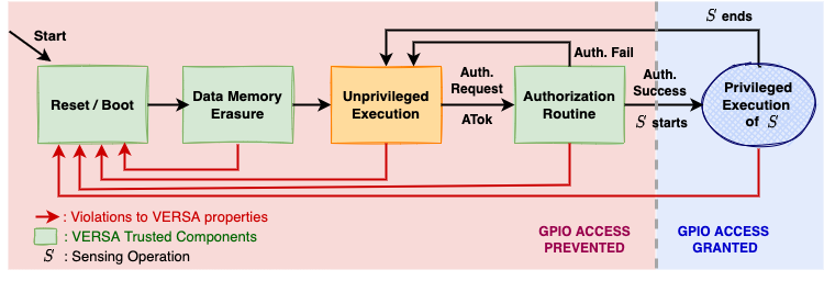
VERSA involves two entities: a trusted remote controller () and a device (). We expect to be a relatively powerful computing entity, e.g., a home gateway, a backend server or even a smartphone. VERSA protects sensed data on by keeping it (and any function thereof) confidential. This implies: (1) controlling GPIO access by blocking attempted reads by unauthorized software, and (2) keeping execution traces (i.e., data allocated by GPIO-authorized software) confidential. Therefore, access to GPIO is barred by default. GPIO is unlocked only for benign binaries that are pre-authorized by . Whenever a binary is deemed to be authorized on , VERSA creates for it an ephemeral isolated execution environment and permits its one-time execution. This isolated environment lasts until execution ends, which corresponds to reaching the legal exit point of the authorized binary. Therefore, by including a clean-up routine immediately before the legal exit, we can assure that all execution traces, including all sensitive information, are erased. Any attempt to interrupt, or tamper with, isolated execution causes an immediate system-wide reset, which erases all data traces.
We use the term “Sensing Operation”, denoted by , to refer to a self-contained and logically independent binary (e.g., a function) that is responsible for processing data obtained through one or more reads from GPIO.
VERSA achieves PfB via three key features:
[A] Mandatory Sensing Operation Authorization requires explicit authorization issued by before any software reads from GPIO. Recall that access to GPIO is blocked by default. Each authorization token (ATok) coming from allows one execution of a specific sensing operation , although a single execution of can implement several GPIO reads. ATok has the following properties:
-
1.
It can be authenticated by as having been issued by ; this includes freshness;
-
2.
It grants privileges only to a specific to access GPIO during its execution; and
-
3.
It can only be used once.
can authorize multiple executions of by issuing a batch of tokens, i.e., , for up to executions of . Although supporting multiple tokens is unnecessary for on-demand sensing, it might be useful for periodic or event-driven sensing regimes discussed in Section II-B.
[B] Atomic Sensing Operation Execution ensures that, once authorized by , is executed with the following requirements:
-
1.
execution starts from its legal entry point (first instruction) and runs until its legal exit point (last instruction). This assumes a single pair of entry-exit points;
-
2.
execution can not be interrupted and its intermediate results cannot be accessed by external means, e.g., via DMA controllers; and
-
3.
An immediate MCU reset is triggered if either (1) or (2) above is violated.
[C] Data Erasure on Reset/Boot works with [B] to guarantee that, sensed data (or any function thereof) obtained during execution is not leaked due to errors or violations of security properties, which cause MCU reset per item (3) above. This feature must guarantee that all values that remain in RAM after a hard reset and the subsequent boot process, are erased before any unprivileged software can run. While some architectures already provide memory erasure on boot, for those MCUs that do not do so, it can be obtained by calling a secure RAM erasure function at boot time, e.g., as a part of a ROM-resident bootloader code. Appendix -B discusses this further.
At a high level, correct implementation of aforementioned three features suffices to obtain PfB, because:
-
•
Any compromised/modified binary can not access GPIO since it has no authorization from .
-
•
Any authorized binary must be invoked properly and run atomically, from its first, and until its last, instruction.
-
•
Since is invoked properly, intended behavior of is preserved. Code reuse attacks are not possible, unless they occure as a result of bugs in implementation itself. can always check for such bugs in prior to authorization; see Section V-B.
-
•
runs uninterrupted, meaning that it can erase all traces of its own execution from the stack before passing control to unprivileged applications. This guarantees that no sensor data remains in memory when terminates.
-
•
VERSA assures that any violation of aforementioned requirements causes an MCU reset, triggering erasure of all data memory. Therefore, malware that attempts to interrupt before completion, or tamper with execution integrity, will cause all data used by to be erased.
Support for Output Encryption: might process and use sensor data locally as part of its own execution, or generate some output that needs to be returned to . In the latter case, encryption of output is necessary. For this reason, VERSA supports the generation of a fresh key derived from ATok (thus implicitly shared between and ). This key is only accessible to during authorized execution. Hence, can encrypt any data to be exported with this key and ensure that encrypted results can only be decrypted by .
Since we assume that the encryption function is part of , it cannot be interrupted (or tampered with) by any unprivileged software or external means. Importantly, the encryption key is only accessible to (similar to GPIO) and shielded from all other software. Furthermore, the choice of the encryption algorithm is left up to the specific implementation.
Figure 2 illustrates MCU execution workflow discussed in this section.
Definition 1 (MCU Execution Model).
1 – Execution is modeled as a sequence of MCU states and a sequence of instructions . Since the next MCU state and the next instruction to be executed are determined by the current MCU state and the current instruction being executed, these discrete transitions are denoted as shown in the following example: The sequence I represents the physical order of instructions in memory, which is not necessarily the order of their execution. The next instruction and state are also affected by current external inputs, current data-memory values, and current hardware events, e.g., interrupts or resets, which are modeled as properties of each execution state in S. The MCU always starts execution (at boot or after a reset) from state and initial instruction . EXEC produces as the next instruction if there is no instructions left to execute. 2 – State Properties as Sets: sets are used to model relevant execution properties and characterize effects/actions occurring within a given state . We are particularly interested in the behaviors corresponding to the following sets: 1. READ: all states produced by the execution of an instruction that reads the value from memory to a register. 2. WRITE: all states produced by the execution of an instruction that writes the value from a register to memory. 3. : all states produced as a result of DMA reading from memory. 4. : all states produced as a result of DMA writing to memory. 5. IRQ: all states where an interrupt is triggered. 6. RESET: all states wherein an MCU reset is triggered. Note that these sets are not disjoint, i.e., can belong to multiple sets. Also, the aforementioned sets do not aim to model all possible MCU behaviors, but only the ones relevant to PfB. Finally, we further subdivide sets that model memory access into subsets relating to memory regions of interest. For example, considering a contiguous memory region , is a subset of READ containing only the states produced through EXEC of instructions that read from the memory region . We use the same notation to refer to other subsets, e.g., , , and .Definition 2 (Hardware Model).
denotes a contiguous memory region within addresses and in physical memory of , i.e., . represents the system execution state at a given CPU cycle.Program counter & instruction execution: (1) Memory Reads/Writes: (2) (3) (4) Interrupts () and Resets: (5) (6)
IV MCU Machine Model
IV-A Execution Model
To enable formal specification of PfB guarantees, we formulate the MCU execution model in Definition 1. It represents MCU operation as a discrete sequence of MCU states, each corresponding to one clock cycle – the smallest unit of time in the system. We say that the subsequent MCU state is defined based on the current MCU state (which includes current values in memory/registers, as well as any hardware signals and effects, such as external inputs, actions by DMA controller(s), and interrupts) and the current instruction being executed by the CPU core. Similarly, the instruction to be executed in the next state is determined by the current state and the current instruction being executed.
For example, an arithmetic instruction (e.g., add or mult) causes the program counter () to point to the subsequent address in physical memory. However, an interrupt (which is a consequence of the current MCU state) may occur and deviate the normal execution flow. Alternatively, a branching instruction may be executed and cause to jump to some arbitrary instruction that is not necessarily located at the subsequent position in the MCU flash memory.
In order to reason about events during the MCU operation, we say that each MCU state can belong to one or more sets. Belonging to a given set implies that the state has a given property of interest. Definition 1 introduces six sets of interest, representing states in which memory is read/written by CPU or DMA, as well as states in which an interrupt or reset occurs.
IV-B Hardware Signals
We now formalize the effects of execution, modeled in Definition 1, to the values of concrete hardware signals that can be monitored by VERSA hardware in order to attain PfB guarantees. Informally, we model the following simple axioms:
-
[A1] PC:
contains the memory address containing the instruction being executed at a given cycle.
-
[A2] CPU Memory Access:
Whenever memory is read or written, a data-address signal () contains the address of the corresponding memory location. A data read-enable bit () must be set for a read access and a data write-enable bit () must be set for a write access.
-
[A3] DMA:
Whenever a DMA controller attempts to access the main memory, a DMA-address signal () contains the address of the accessed memory location and a DMA-enable bit () must be set.
-
[A4] Interrupts:
When hardware interrupts or software interrupts happen, the signal is set.
-
[A5] MCU reset:
At the end of a successful reset routine, all registers (including ) are set to zero before restarting software execution. The reset handling routine cannot be modified, as resets are handled by MCU in hardware. When a reset happens, the corresponding signal is set. The same signal is also set when the MCU initializes for the first time.
This model strictly adheres to MCU specifications, assumed to be correctly implemented by the underlying MCU core.
Definition 2 presents formal specifications for aforementioned axioms in LTL. Instead of explicitly quantifying time, LTL embeds time within the logic by using temporal quantifiers (see Section II). Hence, rather than referring to execution states using temporal variables (i.e., state , state , state ), a single variable () and LTL quantifiers suffice to specify, e.g., “current”, “next”, “future” system states (). For this part of the model, we are mostly interested in: (1) describing MCU state at the next CPU cycle () as a function of the MCU state at the current CPU cycle (), and (2) describing which particular MCU signals must be triggered in order for to be in each of the sets defined in Definition 1.
V PfB Definitions
Definition 3 (Syntax: PfB scheme).
A Privacy-from-Birth (PfB) scheme is a tuple of algorithms : 1. : an algorithm executed by taking as input at least one executable and producing at least one authorization token ATok which can be sent to to authorize one execution of with access to GPIO.2. : an algorithm (with possible hardware-support), executed by , that takes as input and ATok. It uses ATok to check whether is pre-authorized by and outputs if verification succeeds, and otherwise.
3. : an algorithm (with possible hardware-support) that executes in , producing a sequence of states . It returns , if sensing successfully occurs during execution, i.e., such that ); it returns , otherwise.
Remark: In the parameter list, () means that additional/optional parameters might be included depending on the specific PfB construction.
Definition 4 (PfB Game-based Definition).
4.1 Auxiliary Notation & Predicate(s): • Let be a secret string of bit-size ; and be the security parameter, determined by , i.e., ; • Let be a predicate evaluated on some sequence of states S and some software – i.e., some sequence of instructions I. – if and only if the following hold; otherwise, . 1. Legal Entry Instruction: The first execution state in S is produced by the execution of the first instruction in I.i.e., , where is any state prior to . 2. Legal Exit Instruction: The last execution state in S is produced by the execution of the last instruction in I.
i.e., . 3. Self-Contained Execution: For all in S, is produced by the execution of an instruction in I, for some .
i.e., , for some . 4. No Interrupts, No DMA: For all in S, is neither in the IRQ or DMA. i.e., . 4.2 PfB-Game: The challenger plays the following game with : 1. is given full control over software state, implying can execute any (polynomially sized) sequence of arbitrary instructions , inducing the associated changes in ’s sequence of execution states; 2. has oracle access to polynomially many calls to . also has access to the set of software executables, , and the set of all corresponding authorization “tokens”, , ever produced by any prior calls to up until time . i.e., , for all . 3. Let be the set of all “used” authorization tokens up until time , i.e., , if a call to returned up until time ; Let be the set of “pending” (issued but not used) authorization tokens, i.e., . 4. At any arbitrary time , wins if it can perform an unauthorized or tampered sensing execution, i.e.: – triggers an operation that returns , for , or – triggers such that , for some and . 4.3 PfB-Security: A scheme is considered PfB-Secure iff, for all PPT adversaries , there exists a negligible function such that:
Based on the specified machine model, we now proceed with the formal definition of PfB.
V-A PfB Syntax
A PfB scheme involves two parties: and . authorizes to execute some software which accesses GPIO. It should be impossible for any software different from to access GPIO data, or any function thereof (see Definition 4). is trusted to only authorize functionally correct code. The goal of a PfB scheme is to facilitate sensing-dependent execution while keeping all sensed data private from all other software.
Definition 3 specifies a syntax for PfB scheme composed of three functionalities: , , and . is invoked by to produce an authorization token, ATok, to be sent to , enabling to access GPIO. is executed at with ATok as input, and it checks whether ATok is a valid authorization for the software on . If and only if this check succeeds, returns . Otherwise, it returns . The verification success indicates one execution of granted on via . is considered successful (returns ), if there is at least one MCU state produced by where a GPIO read occurs without causing an MCU , i.e., . Otherwise, returns . That is, models execution of any software in the MCU and its return symbol indicates whether a GPIO read occurred during its execution. Therefore, invocation of on any input software that does not read from GPIO returns . Figure 3 illustrates a benign PfB interaction between and .
V-B Assumptions & Adversarial Model
We consider an adversary, , that controls the entire software state of , including PMEM (flash) and DMEM (DRAM). It can attempt to modify any writable memory (including PMEM) or read any memory, including peripheral regions, such as GPIO, unless explicitly protected by verified hardware. It can launch code injection attacks to execute arbitrary instructions from PMEM or even DMEM (if the MCU architecture supports execution from DMEM). It also has full control over any DMA controllers on that can directly read/write to any part of the memory independently of the CPU. It can induce interrupts to pause any software execution and leak information from its stack, or change its control-flow. We consider Denial-of-Service (DoS) attacks, whereby abuses PfB functionality in order to render unavailable, to be out-of-scope. These are attacks on availability and not on sensed data privacy.
Executable Correctness: we stress that VERSA aims to guarantee that , as specified by , is the only software that can access and process GPIO data. Similar to other trusted hardware architectures, PfB does not check for lack of implementation bugs within ; thus it is not concerned with run-time (e.g., control-flow and data-only) attacks. As a relatively powerful and trusted entity can use various well-known vulnerability detection methods, e.g., fuzzing [47], static analysis [48], and even formal verification, to scrutinize before authorizing it.
Physical Attacks: physical and hardware-focused attacks are considered out of scope. We assume that cannot modify code in ROM, induce hardware faults, or retrieve ’s secrets via side-channels that require ’s physical presence. Protection against such attacks can be obtained via standard physical security techniques [49]. This assumption is in line with related work on trusted hardware architectures for embedded systems [16, 18, 21, 20].
V-C PfB Game-based Definition
Definition 4 starts by introducing an auxiliary predicate . It defines whether a particular sequence of execution states (produced by the execution of some software ) adheres to all necessary execution properties for Atomic Sensing Operation Execution discussed in Section III.
In (in Definition 4.1), conditions 1-3 guarantee that a given is executed as a whole and no external instruction is executed between its first and last instructions. Condition 4 assures that DMA is inactive during execution, hence protecting intermediate variables in DMEM against DMA tampering. Additionally, malicious interrupts could be leveraged to illegally change the control-flow of during its execution. Therefore, condition 4 stipulates that both cases cause to return .
PfB-Game in Definition 4.2 models ’s capabilities by allowing it to execute any sequence of (polynomially many) instructions. This models ’s full control over software executed on the MCU, as well as its ability to use software to modify memory at will. It can also call any (polynomial) number of times in an attempt to gain an advantage (e.g., learn something) from executions.
To win the game, must succeed in executing some software that does not cause an MCU reset, and either: (1) is unauthorized, yet reads from GPIO, or (2) is authorized, yet violates predicate conditions during its execution.
VI VERSA: Realizing PfB
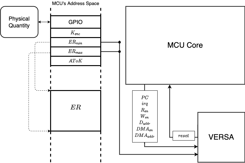
VERSA runs in parallel with the MCU core and monitors a set of MCU signals: , , , , , , and . It also monitors and , the boundary memory addresses of where is stored; these are collectively referred to as “METADATA”. VERSA hardware module detects privacy violations in real-time, based on aforementioned signals and METADATA values, causing an immediate MCU reset. Figure 4 shows the VERSA architecture. For quick reference, MCU signals and memory regions relevant to VERSA are summarized in Table I. To facilitate specification of VERSA properties, we introduce the following two macros:
representing read/write from/to a particular memory address by either CPU or DMA. For reads/writes from/to some continuous memory region (composed of multiple addresses) , we instead say to denote that . The same holds for notation .
| Notation | Description |
|---|---|
| Current program counter value | |
| 1-bit signal that indicates if MCU is reading from memory | |
| 1-bit signal that indicates if MCU is writing to memory | |
| Memory address of an MCU memory access | |
| 1-bit signal that indicates if DMA is active | |
| Memory address being accessed by DMA, when active | |
| 1-bit signal that indicates if an interrupt is happening | |
| Signal that reboots the MCU when set to logic ‘1’ | |
| A configurable memory region where the sensing operation is stored, | |
| METADATA | Metadata memory region; contains and |
| ATok | Fixed memory region from which reads the authorization token when called |
| GPIO | Memory region that is mapped to GPIO port |
| Memory region storing code which instantiates VRASED software and its hardware protection | |
| A fixed address in , only be reachable (i.e., ) by a successful call (i.e., returns ) | |
| (Optional) memory region for the encryption key necessary to encrypt the output (relevant to sensed data) |
VI-A VERSA: Construction
Construction 1.
VERSA instantiates a PfB = scheme as follows:– is a symmetric key pre-shared between and VRASED secure architecture in ; 1. : produces an authorization message , where is a software, i.e., a sequence of instructions , that wants to execute on ; is a monotonically increasing challenge; and ATok is an authentication token computed as below. sends M to . Upon receiving M, is expected to parse M, find the memory region for , and execute (see below). (7) 2. : calls VRASED functionality [18] on memory region to securely compute: (8) If , output ; Otherwise, output .
3. : starts execution of software in by jumping to (i.e., setting = ). A benign call to with input is expected to occur after one successful computation of for the same region and contents therein. Otherwise, VERSA hardware support (see below) will cause the MCU to reset when GPIO is read. produces , the set of states produced by executing , and outputs or as follows: (9) 4. : At all times, VERSA verified hardware enforces all following LTL properties :
A – Read-Access Control to GPIO: (10) (11) B – Ephemeral Immutability of and METADATA (12) (13) (14) C – Atomicity and Controlled Invocation of : (15) (16) (17) [Optional] Read/Write-Access Control to Encryption Key () in : (18) (19) (20) Remark: [Optional] properties are needed only if support for encryption of outputs is desired.
Recall the key features of VERSA from Section III. To guarantee Mandatory Sensing Operation Authorization and Atomic Sensing Operation Execution, VERSA constructs PfB = algorithms as in Construction 1. We describe each algorithm below.
:
To authorize , picks a monotonically increasing and generates ATok := (this follows VRASED authentication algorithm – see VERSA specification below). ATok is computed over with a one-time key derived from and , where is the master secret key shared between and .
:
To securely verify that an executable ’, installed in , matches authorized , invokes VRASED 444 and act as and in VRASED respectively. to compute := . outputs , iff . In this case, reaches a fixed address, called . Otherwise, outputs .
In the rest of this section, we use “authorized software" to refer to software located in , for which outputs . Whereas, “unauthorized software" refers to any software for which outputs .
:
When () is invoked, jumps to , and starts executing the code in . It produces a set E of states by executing , and outputs , if there is at least one state that reads GPIO without triggering an MCU reset. Otherwise, it outputs .
:
A – Read-Access Control to GPIO is jointly specified by LTLs (10) and (11). LTL (10) states that GPIO can only be read during execution of (), requiring an MCU reset otherwise. LTL (11) forbids all GPIO reads (even those within execution) before successful computation of on binary using a valid ATok. Successful computation is captured by condition . A new successful computation of is necessary whenever execution completes () or after reset/boot. Hence, each legitimate ATok can be used to authorize execution once.
B – Ephemeral Immutability of and METADATA is specified by LTLs (12)-(14). From the time when binary is authorized until it starts executing, no modifications to or METADATA are allowed. LTL (12) specifies that no such modification is allowed at the moment when verification succeeds (); LTL (13) requires to be re-authorized from scratch if or METADATA are ever modified. Whenever these modifications are detected ) further reads to GPIO are immediately blocked () until subsequent re-authorization of is completed (). LTL (14) specifies the same requirement in order to read VERSA-provided encryption key () which is stored in memory region . This property is only required when support for encryption of outputs is desired.
C – Atomicity & Controlled Invocation of are enforced by LTLs (15), (16), and (17). They specify that execution must start at and end at . Specifically, they use the relation between current and next values. The only legal transition from currently outside of to next inside is via . Similarly, the only legal transition from currently inside to next outside is via . All other cases trigger an MCU reset. In addition, LTL (17) requires an MCU reset whenever interrupts or DMA activity is detected during execution. This is done by simply checking and signals.
We note that relies on the to reset the MCU when violations to atomic execution are detected. Upon reset all data is erased from memory. However, when execution of completes successfully VERSA does not trigger resets. In this case, is responsible for erasing its own stack before completion (reaching of its last instruction). We discuss how this self-clean-up routine can be implemented as a part of behavior in Appendix -A.
VI-B Encryption & Integrity of Output
As mentioned in Section III, after reading and processing GPIO inputs, might need to encrypt and send the result to . VERSA supports encryption of this output, regardless of the underlying encryption scheme. For that purpose, implementation derives a fresh one-time encryption key () from and . To assure confidentiality of , the following properties are required for the memory region () reserved to store :
-
1.
is writable only by (i.e., ); and
-
2.
is readable only by after authorization.
LTLs (18)-(20) and (14) specify the confidentiality requirements of . In sum, these properties establish the same read access-control policy for and GPIO regions. Therefore, only authorized is able to retrieve .
VII Verified Implementation & Security Analysis
VII-A Sub-module Implementation & Verification
VERSA sub-modules are represented as FSMs and individually verified to hold for LTL properties from Construction 1. They are implemented in Verilog HDL as Mealy machines, i.e., their output is determined by both their current state and current inputs. Each FSM has a single output: a local . VERSA global output is given by the disjunction (logic ) of all local -s. For simplicity, instead of explicitly representing the output value for each state, we use the following convention:
-
1.
is whenever an FSM transitions to state;
-
2.
remains while on state;
-
3.
is otherwise.
Note that all FSMs remain in state until which indicates that the MCU reset routine finished.
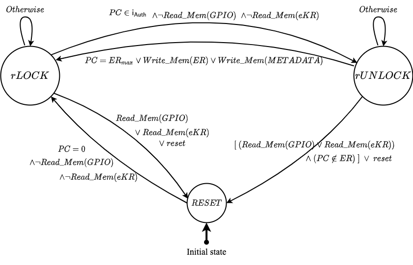
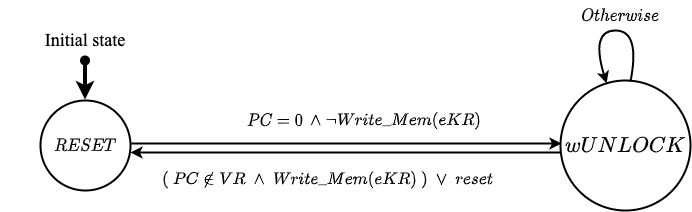
Fig. 6 illustrates the VERSA sub-module that implements read-access control to GPIO and (when applicable). It guarantees that such reads are only possible when they emanate from execution of authorized software contained in . It also assures that no modifications to or METADATA occur between authorization of and its subsequent execution. The Verilog implementation of this FSM is formally verified to adhere to LTLs (10)-(14) and (18)-(19). It has 3 states: (1) , when reads to GPIO (and possibly ) are disallowed; (2) , when such reads are allowed to ; and (3) . The initial state (after reset or boot) is , and it switches to state when . It switches to when (with no reads to GPIO and ), indicating that was successful. Note that transitions to when reads are attempted from outside , thus preventing reads by any unauthorized software. Once reaches , indicating that execution has finished, the FSM transitions back to . Also, any attempted modifications to METADATA or in state bring the FSM back to . Note that is only reachable after authorization of , i.e., .
Definition 5.
Atomic Sensing Operation Execution:Definition 6.
Mandatory Sensing Operation Authorization:The FSM in Figure 7 enforces LTL (20) to protect from external writes. It has two states: (1) , when writes to are allowed; and (2) . At boot/after reset (), this FSM transitions from to . It transitions back to state whenever writes to are attempted, unless these writes come from execution ().
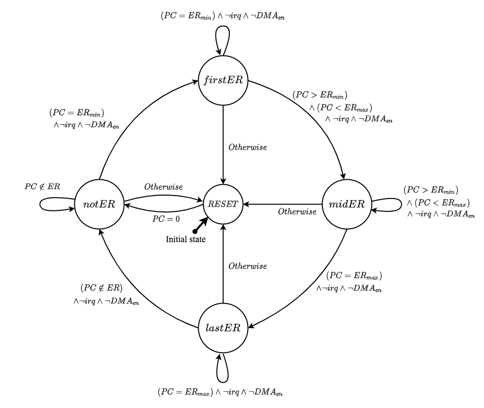
Figure 8 shows the FSM verified to enforce atomicity and controlled invocation: LTLs (15)-(17). It has five states; and correspond to being outside and within (not including and ), respectively. and are states in which points to and , respectively. The only path from to is via . Likewise, the only path from to is via . The FSM transitions to whenever transitions do not follow aforementioned paths. It also transitions to (from any state other than ) if or signals are set.
VII-B Sub-module Composition and VERSA End-To-End Security
To demonstrate security of VERSA according to Definition 4, our strategy is two-pronged:
-
A)
We show that LTL properties from Construction 1 are sufficient to imply that GPIO (and ) is only readable by and any operation that returns (i.e., performs sensing) is executed atomically. The former is formally specified in Definition 6, and the latter in Definition 5. For this part, we write an LTL computer proof using SPOT LTL proof assistant [46].
-
B)
We use a cryptographic reduction to show that, as long as item A holds, VRASED security can be reduced to VERSA security according to Definition 4.
The intuition for this strategy is that, to win PfB-game in Definition 4, must either break the atomicity of (which is in direct conflict with Definition 5) or execute with unauthorized software and read GPIO without causing an MCU . Definition 6 guarantees that the latter is not possible without a prior successful call to . On the other hand, is implemented using VRASED verified architecture, which guarantees the unforgeability of ATok. Hence, breaking VERSA requires either violating VERSA verified guarantees or breaking VRASED verified guarantees, which should be infeasible to any PPT .
Appendix -C includes proofs for Theorems 1, 2, and 3, in accordance to this proof strategy. The rest of this section focuses on VERSA end-to-end implementation goals captured by LTLs in Definitions 5 and 6 as well as their relation to VERSA high-level features discussed in Section III.
Theorem 1.
Definition 2 LTL 15, 16, 17 Definition 5Theorem 2.
Definition 2 LTL 10, 11, 12, 13, 16, 20 Definition 6Theorem 3.
VERSA is secure according to the PfB-game in Definition 4, as long as VRASED is a secure architecture according to VRASED security game from [18].[Definition 5] states that it globally (always) holds that is atomically executed with controlled invocation. That is, whenever an instruction in executes (), it keeps executing instructions within (), with no interrupts and no DMA enabled, until reaches the last instruction in or an MCU reset occurs. Also, if an instruction in starts to execute, it always begins with the first instruction in . This formally specifies the Atomic Sensing Operation Execution feature discussed in Section III.
[Definition 6] globally requires that whenever GPIO is successfully read (i.e., without a ), this read must come from the CPU while is being executed. In addition, before this read operation, the following must have happened at least once:
-
(1)
succeeded (i.e., );
-
(2)
From the time when until starts executing (i.e., ), no modification to and METADATA occurred; and
-
(3)
If there was any write to from the time when , until , it must have been from , i.e., while .
This formally specifies the intended behavior of the Mandatory Sensing Operation Authorization feature, discussed in Section III.
VIII Evaluation & Discussion
In this section, we discuss VERSA implementation details and evaluation. VERSA source code and verification/proofs are publicly available at [33]. Evaluation of verification costs and discussion of VERSA limitations are deferred to Appendix -D.
VIII-A Toolchain & Prototype Details
VERSA is built atop OpenMSP430 [36]: an open source implementation of TI-MSP430 [50]. We use Xilinx Vivado to synthesize an RTL description of and deploy it on Diligent Basys3 prototyping board for Artix7 FPGA. For the software part (mostly to implement ), VERSA extends VRASED software (which computes over memory) to include a comparison with the received ATok (See Section VIII-C for extension details). We use the NuSMV model checker to formally verify that implementation adheres to LTL specifications (10)-(20). See Appendix -D for details on the verification setup and costs.
VIII-B Hardware Overhead
Table II reports on VERSA hardware overhead, as compared to unmodified OpenMSP430 and VRASED. Similar to other schemes [18, 22, 17, 16], we consider hardware overhead in terms of additional Look-Up Tables (LUTs) and registers. Extra hardware in terms of LUTs gives an estimate of additional chip cost and size required for combinatorial logic, while extra hardware in terms of registers gives an estimate of memory overhead required by sequential logic in VERSA FSMs. Compared to VRASED, VERSA requires 10% additional LUTs and 2% additional registers. In actual numbers, it adds 255 LUTs and 50 registers to the underlying MCU as shown in Table II.
| Architecture | Hardware | Reserved | Verification | ||||
|---|---|---|---|---|---|---|---|
| LUTs | Regs | RAM (bytes) | LoC | #(LTLs) | Time (s) | RAM (MB) | |
| OpenMSP430 | 1854 | 692 | 0 | - | - | - | - |
| VRASED | 1891 | 724 | 2332 | 481 | 10 | 0.4 | 13.6 |
| VERSA + VRASED | 2109 | 742 | 2336 | 1118 | 21 | 13956.4 | 1059.1 |
VIII-C Runtime Overhead
VERSA requires any software piece seeking to access GPIO (and ) to be verified. Consequently, runtime overhead is due to computation which instantiates VRASED. This runtime includes: (1) time to compute from equation 8; (2) time to check if ; and (3) time to write to , when applicable. Naturally the runtime overhead is dominated by the computation in (1) which is proportional to the size of .
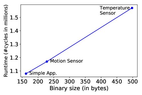
We measure cost on three sample applications: (1) Simple Application, which reads 32-bytes of GPIO input and encrypts it using One-Time-Pad (OTP) with ; (2) Motion Sensor – available at [51] – which continuously reads GPIO input to detect movements and actuates a light source when movement is detected; and (3) Temperature Sensor – adapted code from [52] to support encryption of its outputs – which reads ambient temperature via GPIO and encrypts this reading using OTP. We prototype using OTP for encryption for the sake of simplicity noting that VERSA does not mandate a particular encryption scheme. All of these sample applications also include a self-clean-up code executed immediately before reaching their exit point to erase their stack traces once their execution is over.
Figure 10 shows runtimes on these applications. Assuming a clock frequency of 10MHz (a common frequency for low-end MCUs), runtime ranges from milliseconds for these applications. The overhead is linear on the binary size.
VIII-D Comparison with Other Low-End Architectures:
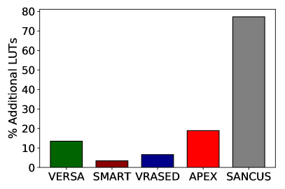
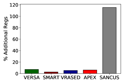
To the best of our knowledge, VERSA is the first architecture related to PfB. However, to provide a point of reference in terms of performance and overhead, we compare VERSA with other low-end trusted hardware architectures, such as SMART [16], VRASED [18], APEX [22], and SANCUS [17]. All these architectures provide -related services to attest integrity of software on either statically or at runtime. Since PfB also checks software integrity before granting access to GPIO, we consider these architectures to be related to VERSA.
Figure 9 compares VERSA hardware overhead with the aforementioned architectures in terms of additional LUTs and registers. Percentages are relative to the plain MSP430 core total cost.
VERSA builds on top of VRASED. As such, it is naturally more expensive than hybrid architectures such as SMART and VRASED. Similar to VERSA, APEX also monitors execution properties and also builds on top of (in APEX case, with the goal of producing proofs of remote software execution). Therefore, VERSA and APEX exhibit similar overheads. SANCUS presents a higher cost because it implements and isolation features in hardware.
IX Related Work
There is a considerable body of work (overviewed in Section I) on IoT/CPS privacy. However, to the best of our knowledge, this paper is the first effort specifically targeting PfB, i.e., sensor data privacy on potentially compromised MCUs. Nonetheless, prior work has proposed trusted hardware/software co-designs – such as VERSA – offering other security services. We overview them in this section.
Trusted components, commonly referred to as Roots of Trust (RoTs), are categorized as software-based, hardware-based, or hybrid (i.e., based on hardware/software co-designs). Their usual purpose is to verify software integrity on a given device. Software-based RoTs [53, 54, 55, 56, 57, 58, 59] usually do not rely on any hardware modifications. However, they are insecure against compromises to the entire software state of a device (e.g., in cases where can physically re-program ). In addition, their inability to securely store cryptographic secrets imposes reliance on strong assumptions about precise timing and constant communication delays to enable device authentication. These assumptions can be unrealistic in the IoT ecosystem. Nonetheless, software-based RoTs are the only viable choice for legacy devices that have no security-relevant hardware support. Hardware-based methods [60, 61, 62, 63, 64, 65, 17] rely on security provided by dedicated hardware components (e.g., TPM [61] or ARM TrustZone [66]). However, the cost of such hardware is normally prohibitive for low-end MCUs. Hybrid RoTs [16, 22, 18, 20, 21] aim to achieve security equivalent to hardware-based mechanisms, yet with lower hardware costs. They leverage minimal hardware support while relying on software to reduce additional hardware complexity.
Other architectures, such as SANCTUM [35] and Notary [67], provide strong memory isolation and peripheral isolation guarantees, respectively. These guarantees are achieved via hardware support or external hardware agents. They are also hybrid architectures where trusted hardware works in tandem with trusted software. However, we note that such schemes are designed for application computers that support MMUs and are therefore unsuitable for simple MCUs.
In terms of functionality, such embedded RoTs focus on integrity. Upon receiving a request from an external trusted Verifier, they can generate unforgeable proofs for the state of the MCU or that certain actions were performed by the MCU. Security services implemented by them include: (1) memory integrity verification, i.e., remote attestation [16, 17, 18, 19, 20, 21]; (2) verification of runtime properties, including control-flow and data-flow attestation [22, 23, 24, 25, 26, 27, 28, 29, 68]; and (3) proofs of remote software updates, memory erasure, and system-wide resets [30, 31, 32]. As briefly mentioned in Section I, due to their reactive nature, they can be used to detect whether has been compromised after the fact, but cannot prevent the compromised entity from exfiltrating private sensor data. VERSA, on the other hand, enforces mandatory authorization before any sensor data access and thus prevents leakage even when a compromise has already happened.
Formalization and formal verification of RoTs for MCUs have gained attention due to the benefits discussed in Sections I and II. VRASED [18] implemented a verified hybrid scheme. APEX [22] built atop VRASED to implement and formally verify an architecture for proofs of remote execution of attested software. PURE [30] implemented provably secure services for software update, memory erasure, and system-wide reset. Another recent result [69] formalized and proved the security of a hardware-assisted mechanism to prevent leakage of secrets through timing side-channels due to MCU interrupts. Inline with the aforementioned work, VERSA also formalizes its assumptions along with its goals and implements the first formally verified design assuring PfB.
X Conclusions
We formulated the notion of Privacy-from-Birth (PfB) and proposed VERSA: a formally verified architecture realizing PfB. VERSA ensures that only duly authorized software can access sensed data even if the entire software state of the sensor is compromised. To attain this, VERSA enhances the underlying MCU with a small hardware monitor, which is shown sufficient to achieve PfB. The experimental evaluation of VERSA publicly available prototype [33] demonstrates its affordability on a typical low-end IoT MCU: TI MSP430.
Acknowledgments
The authors sincerely thank S&P’22 reviewers. This work was supported by funding from NSF Awards SATC-1956393 and CICI-1840197, as well as a subcontract from Peraton Labs. Part of this work was conducted while the first author was at the University of California, Irvine.
References
- [1] R. H. Weber, “Internet of things–new security and privacy challenges,” Computer law & security review, vol. 26, no. 1, pp. 23–30, 2010.
- [2] A. Ukil, S. Bandyopadhyay, and A. Pal, “Iot-privacy: To be private or not to be private,” in 2014 IEEE Conference on Computer Communications Workshops (INFOCOM WKSHPS). IEEE, 2014, pp. 123–124.
- [3] H. Lin and N. W. Bergmann, “Iot privacy and security challenges for smart home environments,” Information, vol. 7, no. 3, p. 44, 2016.
- [4] S. Zheng, N. Apthorpe, M. Chetty, and N. Feamster, “User perceptions of smart home iot privacy,” Proceedings of the ACM on Human-Computer Interaction, vol. 2, no. CSCW, pp. 1–20, 2018.
- [5] P. Porambage, M. Ylianttila, C. Schmitt, P. Kumar, A. Gurtov, and A. V. Vasilakos, “The quest for privacy in the internet of things,” IEEE Cloud Computing, vol. 3, no. 2, pp. 36–45, 2016.
- [6] A. L. M. Neto, A. L. Souza, I. Cunha, M. Nogueira, I. O. Nunes, L. Cotta, N. Gentille, A. A. Loureiro, D. F. Aranha, H. K. Patil et al., “Aot: Authentication and access control for the entire iot device life-cycle,” in Proceedings of the 14th ACM Conference on Embedded Network Sensor Systems CD-ROM, 2016, pp. 1–15.
- [7] S. Kumar, Y. Hu, M. P. Andersen, R. A. Popa, and D. E. Culler, “: Many-to-many end-to-end encryption and key delegation for iot,” in 28th USENIX Security Symposium (USENIX Security 19), 2019, pp. 1519–1536.
- [8] R. Trimananda, J. Varmarken, A. Markopoulou, and B. Demsky, “Packet-level signatures for smart home devices,” in Network and Distributed Systems Security (NDSS) Symposium, vol. 2020, 2020.
- [9] N. Apthorpe, D. Y. Huang, D. Reisman, A. Narayanan, and N. Feamster, “Keeping the smart home private with smart (er) iot traffic shaping,” arXiv preprint arXiv:1812.00955, 2018.
- [10] N. Apthorpe, D. Reisman, and N. Feamster, “Closing the blinds: Four strategies for protecting smart home privacy from network observers,” arXiv preprint arXiv:1705.06809, 2017.
- [11] N. J. Apthorpe, D. Reisman, and N. Feamster, “A smart home is no castle: Privacy vulnerabilities of encrypted iot traffic,” CoRR, vol. abs/1705.06805, 2017. [Online]. Available: http://arxiv.org/abs/1705.06805
- [12] Y. Cheng, X. Ji, X. Zhou, and W. Xu, “Homespy: Inferring user presence via encrypted traffic of home surveillance camera.” in ICPADS, 2017, pp. 779–782.
- [13] S. Narain, T. D. Vo-Huu, K. Block, and G. Noubir, “Inferring user routes and locations using zero-permission mobile sensors,” in 2016 IEEE Symposium on Security and Privacy (SP). IEEE, 2016, pp. 397–413.
- [14] A. S. A. Sukor, A. Zakaria, N. A. Rahim, L. M. Kamarudin, R. Setchi, and H. Nishizaki, “A hybrid approach of knowledge-driven and data-driven reasoning for activity recognition in smart homes,” Journal of Intelligent & Fuzzy Systems, vol. 36, no. 5, pp. 4177–4188, 2019.
- [15] M. Jin, R. Jia, and C. J. Spanos, “Virtual occupancy sensing: Using smart meters to indicate your presence,” IEEE Transactions on Mobile Computing, vol. 16, no. 11, pp. 3264–3277, 2017.
- [16] K. Eldefrawy, G. Tsudik, A. Francillon, and D. Perito, “SMART: Secure and minimal architecture for (establishing dynamic) root of trust,” in NDSS, 2012.
- [17] J. Noorman, J. V. Bulck, J. T. Mühlberg, F. Piessens, P. Maene, B. Preneel, I. Verbauwhede, J. Götzfried, T. Müller, and F. C. Freiling, “Sancus 2.0: A low-cost security architecture for iot devices,” ACM Trans. Priv. Secur., vol. 20, no. 3, pp. 7:1–7:33, 2017. [Online]. Available: https://doi.org/10.1145/3079763
- [18] I. De Oliveira Nunes, K. Eldefrawy, N. Rattanavipanon, M. Steiner, and G. Tsudik, “VRASED: A verified hardware/software co-design for remote attestation,” in USENIX Security, 2019.
- [19] M. Ammar, B. Crispo, and G. Tsudik, “Simple: A remote attestation approach for resource-constrained iot devices,” in 2020 ACM/IEEE 11th International Conference on Cyber-Physical Systems (ICCPS). IEEE, 2020, pp. 247–258.
- [20] F. Brasser, B. E. Mahjoub, A. Sadeghi, C. Wachsmann, and P. Koeberl, “Tytan: tiny trust anchor for tiny devices,” in Proceedings of the 52nd Annual Design Automation Conference, San Francisco, CA, USA, June 7-11, 2015. ACM, 2015, pp. 34:1–34:6. [Online]. Available: https://doi.org/10.1145/2744769.2744922
- [21] P. Koeberl, S. Schulz, A.-R. Sadeghi, and V. Varadharajan, “TrustLite: A security architecture for tiny embedded devices,” in EuroSys, 2014.
- [22] I. De Oliveira Nunes, K. Eldefrawy, N. Rattanavipanon, and G. Tsudik, “APEX: A verified architecture for proofs of execution on remote devices under full software compromise,” in 29th USENIX Security Symposium (USENIX Security 20). Boston, MA: USENIX Association, Aug. 2020. [Online]. Available: https://www.usenix.org/conference/usenixsecurity20/presentation/nunes
- [23] G. Dessouky, T. Abera, A. Ibrahim, and A.-R. Sadeghi, “Litehax: lightweight hardware-assisted attestation of program execution,” in 2018 IEEE/ACM International Conference on Computer-Aided Design (ICCAD). IEEE, 2018, pp. 1–8.
- [24] T. Abera, N. Asokan, L. Davi, J. Ekberg, T. Nyman, A. Paverd, A. Sadeghi, and G. Tsudik, “C-FLAT: control-flow attestation for embedded systems software,” in Proceedings of the 2016 ACM SIGSAC Conference on Computer and Communications Security, Vienna, Austria, October 24-28, 2016, E. R. Weippl, S. Katzenbeisser, C. Kruegel, A. C. Myers, and S. Halevi, Eds. ACM, 2016, pp. 743–754. [Online]. Available: https://doi.org/10.1145/2976749.2978358
- [25] G. Dessouky, S. Zeitouni, T. Nyman, A. Paverd, L. Davi, P. Koeberl, N. Asokan, and A.-R. Sadeghi, “Lo-fat: Low-overhead control flow attestation in hardware,” in Proceedings of the 54th Annual Design Automation Conference 2017. ACM, 2017, p. 24.
- [26] S. Zeitouni, G. Dessouky, O. Arias, D. Sullivan, A. Ibrahim, Y. Jin, and A.-R. Sadeghi, “Atrium: Runtime attestation resilient under memory attacks,” in Proceedings of the 36th International Conference on Computer-Aided Design. IEEE Press, 2017, pp. 384–391.
- [27] Z. Sun, B. Feng, L. Lu, and S. Jha, “Oat: Attesting operation integrity of embedded devices,” in 2020 IEEE Symposium on Security and Privacy (SP). IEEE, 2020, pp. 1433–1449.
- [28] I. De Oliveria Nunes, S. Jakkamsetti, and G. Tsudik, “Tiny-CFA: Minimalistic control-flow attestation using verified proofs of execution,” in Design, Automation and Test in Europe Conference (DATE), 2021.
- [29] I. De Oliveira Nunes, S. Jakkamsetti, and G. Tsudik, “Dialed: Data integrity attestation for low-end embedded devices,” 2021.
- [30] I. De Oliveira Nunes, K. Eldefrawy, N. Rattanavipanon, and G. Tsudik, “Pure: Using verified remote attestation to obtain proofs of update, reset and erasure in low-end embedded systems,” 2019.
- [31] M. Ammar and B. Crispo, “Verify&revive: Secure detection and recovery of compromised low-end embedded devices,” in Annual Computer Security Applications Conference, 2020, pp. 717–732.
- [32] N. Asokan, T. Nyman, N. Rattanavipanon, A.-R. Sadeghi, and G. Tsudik, “ASSURED: Architecture for secure software update of realistic embedded devices,” IEEE Transactions on Computer-Aided Design of Integrated Circuits and Systems, vol. 37, no. 11, 2018.
- [33] “VERSA source code,” https://github.com/sprout-uci/pfb, 2022.
- [34] Intel, “Intel Software Guard Extensions (Intel SGX),” https://software.intel.com/en-us/sgx.
- [35] V. Costan, I. Lebedev, and S. Devadas, “Sanctum: Minimal hardware extensions for strong software isolation,” in 25th USENIX Security Symposium (USENIX Security 16), 2016.
- [36] O. Girard, “openMSP430,” 2009. [Online]. Available: https://opencores.org/projects/openmsp430
- [37] John Wiley & Sons, Ltd, 2010, pp. 295–300. [Online]. Available: https://onlinelibrary.wiley.com/doi/abs/10.1002/9780470570517
- [38] J.-K. Zinzindohoué, K. Bhargavan, J. Protzenko, and B. Beurdouche, “Hacl*: A verified modern cryptographic library,” in CCS, 2017.
- [39] I. De Oliveira Nunes, S. Jakkamsetti, N. Rattanavipanon, and G. Tsudik, “On the toctou problem in remote attestation,” CCS, 2021.
- [40] E. Aliaj, I. D. O. Nunes, and G. Tsudik, “GAROTA: generalized active root-of-trust architecture,” CoRR, vol. abs/2102.07014, 2021. [Online]. Available: https://arxiv.org/abs/2102.07014
- [41] D. W. Loveland, Automated Theorem Proving: a logical basis. Elsevier, 2016.
- [42] E. M. Clarke Jr, O. Grumberg, D. Kroening, D. Peled, and H. Veith, Model checking. MIT press, 2018.
- [43] A. Cimatti, E. Clarke, E. Giunchiglia, F. Giunchiglia, M. Pistore, M. Roveri, R. Sebastiani, and A. Tacchella, “Nusmv 2: An opensource tool for symbolic model checking,” in CAV, 2002.
- [44] A. Irfan, A. Cimatti, A. Griggio, M. Roveri, and R. Sebastiani, “Verilog2SMV: A tool for word-level verification,” in Design, Automation & Test in Europe Conference & Exhibition (DATE), 2016, 2016.
- [45] K. L. McMillan, “The smv system,” in Symbolic Model Checking. Springer, 1993, pp. 61–85.
- [46] A. Duret-Lutz, A. Lewkowicz, A. Fauchille, T. Michaud, E. Renault, and L. Xu, “Spot 2.0—a framework for ltl and -automata manipulation,” in International Symposium on Automated Technology for Verification and Analysis, 2016.
- [47] J. Chen, W. Diao, Q. Zhao, C. Zuo, Z. Lin, X. Wang, W. C. Lau, M. Sun, R. Yang, and K. Zhang, “Iotfuzzer: Discovering memory corruptions in iot through app-based fuzzing.” in NDSS, 2018.
- [48] A. Costin, J. Zaddach, A. Francillon, and D. Balzarotti, “A large-scale analysis of the security of embedded firmwares,” in 23rd USENIX Security Symposium (USENIX Security 14), 2014, pp. 95–110.
- [49] S. Ravi, A. Raghunathan, and S. Chakradhar, “Tamper resistance mechanisms for secure embedded systems,” in VLSI Design, 2004.
- [50] T. Instruments. Msp430 ultra-low-power sensing & measurement mcus. http://www.ti.com/microcontrollers/msp430-ultra-low-power-mcus/overview.html.
- [51] “Motion sensor code,” https://github.com/Seeed-Studio/LaunchPad_Kit/tree/master/Grove_Modules/pir_motion_sensor.
- [52] “Temperature sensor code,” https://github.com/Seeed-Studio/LaunchPad_Kit/tree/master/Grove_Modules/temp_humi_sensor.
- [53] R. Kennell and L. H. Jamieson, “Establishing the genuinity of remote computer systems,” in USENIX Security Symposium, 2003.
- [54] A. Seshadri, A. Perrig, L. Van Doorn, and P. Khosla, “SWATT: Software-based attestation for embedded devices,” in IEEE Symposium on Research in Security and Privacy (S&P). Oakland, California, USA: IEEE, 2004, pp. 272–282.
- [55] A. Seshadri, M. Luk, E. Shi, A. Perrig, L. van Doorn, and P. Khosla, “Pioneer: Verifying code integrity and enforcing untampered code execution on legacy systems,” in ACM SOSP, 2005.
- [56] A. Seshadri, M. Luk, and A. Perrig, “SAKE: Software attestation for key establishment in sensor networks,” in DCOSS, 2008.
- [57] R. W. Gardner, S. Garera, and A. D. Rubin, “Detecting code alteration by creating a temporary memory bottleneck,” IEEE TIFS, 2009.
- [58] Y. Li, J. M. McCune, and A. Perrig, “VIPER: Verifying the integrity of peripherals’ firmware,” in ACM CCS, 2011.
- [59] V. D. Gligor and S. L. M. Woo, “Establishing software root of trust unconditionally.” in NDSS, 2019.
- [60] N. L. Petroni Jr, T. Fraser, J. Molina, and W. A. Arbaugh, “Copilot — A coprocessor-based kernel runtime integrity monitor,” in USENIX Security Symposium, 2004.
- [61] Trusted Computing Group., “Trusted platform module (tpm),” 2017. [Online]. Available: http://www.trustedcomputinggroup.org/work-groups/trusted-platform-module/
- [62] X. Kovah, C. Kallenberg, C. Weathers, A. Herzog, M. Albin, and J. Butterworth, “New results for timing-based attestation,” in Proceedings of the IEEE Symposium on Research in Security and Privacy. IEEE Computer Society Press, 2012.
- [63] D. Schellekens, B. Wyseur, and B. Preneel, “Remote attestation on legacy operating systems with trusted platform modules,” Science of Computer Programming, vol. 74, no. 1, pp. 13 – 22, 2008.
- [64] J. M. McCune, B. J. Parno, A. Perrig, M. K. Reiter, and H. Isozaki, “Flicker: An execution infrastructure for tcb minimization,” in Proceedings of the 3rd ACM SIGOPS/EuroSys European Conference on Computer Systems 2008, 2008, pp. 315–328.
- [65] J. M. McCune, Y. Li, N. Qu, Z. Zhou, A. Datta, V. Gligor, and A. Perrig, “TrustVisor: Efficient TCB reduction and attestation,” in IEEE S&P ’10, 2010.
- [66] Arm Ltd., “Arm TrustZone,” https://www.arm.com/products/security-on-arm/trustzone, 2018.
- [67] A. Athalye, A. Belay, M. F. Kaashoek, R. Morris, and N. Zeldovich, “Notary: A device for secure transaction approval,” in Proceedings of the 27th ACM Symposium on Operating Systems Principles, ser. SOSP ’19. New York, NY, USA: Association for Computing Machinery, 2019, p. 97–113. [Online]. Available: https://doi.org/10.1145/3341301.3359661
- [68] M. Geden and K. Rasmussen, “Hardware-assisted remote runtime attestation for critical embedded systems,” in 2019 17th International Conference on Privacy, Security and Trust (PST). IEEE, 2019, pp. 1–10.
- [69] M. Busi, J. Noorman, J. Van Bulck, L. Galletta, P. Degano, J. T. Mühlberg, and F. Piessens, “Provably secure isolation for interruptible enclaved execution on small microprocessors,” in 2020 IEEE 33rd Computer Security Foundations Symposium (CSF). IEEE, 2020, pp. 262–276.
- [70] “Msp430 flash memory characteristics,” https://www.ti.com/lit/an/slaa334b/slaa334b.pdf?ts=1638460551489, 2018.
- [71] “Avr atmega 1284p 8-bit microcontroller,” http://ww1.microchip.com/downloads/en/DeviceDoc/doc8059.pdf, 2009.
- [72] E. Aras, M. Ammar, F. Yang, W. Joosen, and D. Hughes, “Microvault: Reliable storage unit for iot devices,” in 2020 16th International Conference on Distributed Computing in Sensor Systems (DCOSS), 2020, pp. 132–140.
-A Clean-up after Program Termination
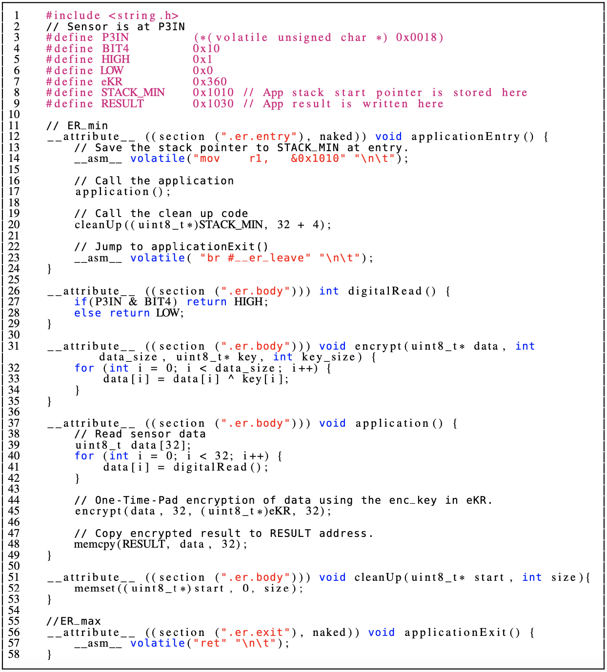
While VERSA guarantees the confidentiality of sensing operations, it requires the authorized executable to erase its own stack/heap before its termination. This ensures that unauthorized software can not extract and leak sensitive information from execution and allocated data. Erasure in this case can be achieved via a single call to libc’s memset function with start address matching the base of stack and size equal to the maximum size reached by execution.
The maximum stack size can be determined manually by counting the allocated local variables in small and simple implementations. To automatically determine this size in more complex implementations, all functions called within must update the highest point reached by their respective stacks. Figure 11 shows a sample application that reads 32 bytes of sensor data, encrypts this data using VERSA one-time key , and cleans-up the stack thereafter. Line 12 is entry point (). first saves the stack pointer to STACK_MIN address. Then, the application function is called, in line 17. application implements intended behavior. After the application is done, the clean up code (lines 51-53) is called with STACK_MIN as the start pointer and size of 32 + 4 bytes (32 bytes for data variable (in line 39) and 4 bytes for stack metadata).
-B Data Erasure on Reset/Boot
Violations to VERSA properties trigger an MCU reset. A reset immediately stops execution and prepares the MCU core to reboot by clearing all registers and pointing the program counter () to the first instruction of PMEM. However, some MCUs may not guarantee erasure of DMEM as a part of this process. Therefore, traces of data allocated by (including sensor data) could persist across resets.
In MCUs that do not offer DMEM erasure on reset, a software-base Data Erasure () can be implemented and invoked it as soon as the MCU starts, i.e., as a part of the bootloader code. In particular, can be implemented using memset (similar to lines 51-53) with constant arguments matching the entirety of the MCU’s DMEM. should be immutable (e.g., stored in ROM) which is often the case for bootloader binaries. Upon reset, must always point to the first instruction of . The normal MCU start-up proceeds normally after execution is completed.
-C VERSA Composition Proof
In this section, we show that VERSA is a secure PfB architecture according to Definition 4, as long as A) the sub-properties in Construction 1 hold (Theorem 1, 2) and B) VRASED is a secure remote attestation () architecture according to the VRASED security definition in [18] (Theorem 3). Informally, part A) shows that if the machine model and all LTLs in Construction 1 hold, then the end-to-end goals for secure PfB architecture are met, while this does not include the goal of prevention of forging authorization tokens. Part B) handles the latter using a cryptographic reduction, i.e., it shows that an adversary able to forge the authorization token (with more than negligible probability) can also break VRASED according to the -game, which is a contradiction assuming the security of VRASED. Therefore, Theorems 1-3 prove that VERSA is a secure PfB architecture as long as VRASED is a secure architecture.
For part A), computer-checked LTL proofs are performed using SPOT LTL proof assistant [46]. These proofs are available at [33]. We present the intuition behind them below.
Proof of Theorem 1 (Intuition).
LTL (16) states the legal entry instruction requirement, while LTL (15) states the legal exit instruction requirement in . Also, since LTL (15) states that is the only possible exit of the without a reset, it implies self-contained execution of . Lastly, LTL (17) enforces MCU reset if any interrupt or DMA occurs, which naturally prevents interrupts and DMA actions, as required by . These imply the LTL in Definition 5 which stipulates that execution of must start with and stays within with no interrupts nor DMA actions, until reaches (causing a reset otherwise). ∎
Proof of Theorem 2 (Intuition).
Definition 6 (i) requires at least one successful verification of before GPIO can be read successfully (without triggering a reset); and (ii) disallows modifications to , METADATA, and (other than by ) in between verification subsequent execution.
LTLs (10) and (11) state that must be within to read GPIO and disallow GPIO reads by default (including when MCU reset occurs) and after the execution of is over (). Also, LTL (11) requires (re-)authorization () of after the execution of is over ().
LTL (13) disallows GPIO reads until the (re-)verification whenever or METADATA are written. LTL (12) disallows changes to and METADATA at the exact time when verification succeeds. LTL (16) guarantees that the execution of starts with and LTL (20) guarantees that only the code can modify the value in . Thus, these are sufficient imply Definition 6. ∎
For part B), we construct a reduction from the security game of VRASED in [18] to the security game of VERSA according to the Definition 4. i.e., The ability to break the PfB-game of VERSA allows to break the -game of VRASED, and therefore, as long as VRASED is a secure architecture according to the -game, VERSA is secure according to the PfB-game.
Proof of Theorem 3. Denote by , an adversary who can win the security game in Definition 4 against VERSA with more than negligible probability. We show that if such exists, then it can be used to construct that wins the -game with more than negligible probability.
Recall that, to win the PfB-game, must trigger as a result of , which means it reads the sensed data without MCU reset. From the PfB-game step 4 in Definition 4, it can be done in either of the following two ways:
Case1. executes a new, unauthorized software which causes ; or
Case2. breaks the atomic execution of an authorized, but not yet executed software, , so that it causes such that .
Recall that for the instruction set of and a set of execution states , to have , at least one of four requirements in Definition 4.1 must be false. Note that the atomic sensing operation execution goal in Definition 5 rules out the probability of Case2. Specifically, LTL (16) enforces 1), while 2) and 3) are guaranteed by LTL (15). Lastly, 4) is covered by LTL (17).
For Case1, i.e., to trigger by running , needs to read GPIO without causing an MCU reset. Recall that the Mandatory Sensing Operation Authorization in Definition 6 requires (with input executable in ) to succeed at least once before reading GPIO. According to VERSA construction, causes to output , where contains which is an unauthorized software, is a valid issued (but never used) token, and is its corresponding challenge. Since function is implemented using VRASED to compute HMAC of and , such can be directly used as to win the -game of VRASED. Thus, assuming secure architecture VRASED, this is a contradiction, which implies the security of VERSA according to the PfB-game. ∎
-D Extended Evaluation & Discussion
Verification Costs: Formal verification costs are reported in Table II. We use a Ubuntu 18.04 desktop machine running at 3.4GHz with 32GB of RAM for formal verification. Our verification pipeline converts Verilog HDL to SMV specification language and then verifies it against the LTL properties listed in Construction 1 using the NuSMV model checker (per Section II). VERSA verification requires checking 11 extra invariants – LTLs (10) to (20) – in addition to VRASED LTL invariants. It also incurs higher run-time and memory usage than VRASED verification. This is due to two additional 16-bit hardware signals (, ) which increase the space of possible input combinations and thus the complexity of model checking process. However, verification is still manageable in a commodity desktop – it takes around 5 minutes and consumes 340MB of memory.
VERSA Limitations:
-D1 Shared Libraries
to verify , must ensure that spans one contiguous memory region () on . If any code dependencies exist outside of , VERSA will reset the MCU according to LTL (17). To preclude this situation, must be made self-contained by statically linking all of its dependencies within .
-D2 Atomic Execution & Interrupts
per Definition 4, VERSA forbids interrupts during execution of . This can be problematic, especially on a with strict real-time constraints. In this case, must be reset in order to allow servicing the interrupt after DMEM erasure. This can cause a delay that could be harmful to real-time settings. Trade-offs between privacy and real-time constraints should be carefully considered when using VERSA. One possibility to remedy this issue is to allow interrupts as long as all interrupt handlers are: (1) themselves immutable and uninterruptible from the start of until its end; and (2) included in memory range and are thus checked by .
-D3 Possible Side-channel Attacks
MSP430 and similar MCU-s allow configuring some GPIO ports to trigger interrupts. If one of such ports is used for triggering an interrupt, could possibly look at the state of and learn information about GPIO data. For example, suppose that a button press mapped to a GPIO port triggers execution of a program that sends some fixed number of packets over the network. Then, can learn that the GPIO port was activated by observing network traffic. To prevent such attacks, privacy-sensitive quantities should always be physically connected to GPIO ports that are not interrupt sources (these are usually the vast majority of available GPIO ports). Other popular timing attacks related to cache side-channels and speculative execution, are not applicable to this class of devices, as these features are not present in low-end MCUs.
-D4 Flash Wear-Out
VERSA implements using VRASED. As discussed in Section II-C, the authentication protocol suggested by VRASED requires persistent storage of the highest value of a monotonically increasing challenge/counter in flash. We note that flash memory has a limited number of write cycles (typically at least 10,000 cycles [70, 71]). Hence, a large number of successive counter updates may wear-out flash causing malfunction. In VRASED authentication, the persistent counter stored in flash is only updated following successful authentication of . Therefore, only legitimate requests from cause these flash writes, limiting the capability of an attacker to exploit this issue. Nonetheless, if the number of expected legitimate calls to is high, one must select the persistent storage type or (alternatively) use different flash blocks once a given flash block storing the counter reaches its write cycles’ limit. For a more comprehensive discussion of this matter, see [72].
VERSA Alternative Use-Case:
VERSA can be viewed as a general technique to control access to memory regions based on software authorization tokens. We apply this framework to GPIO in low-end MCUs. Other use-cases are possible. For example, a VERSA-like architecture could be used to mark a secure storage region and grant access only to explicitly authorized software. This could be useful if runs multiple (mutually distrusted) applications and data must be securely shared between subsets thereof.