Parametric Reshaping of Portraits in Videos
Abstract.
Sharing short personalized videos to various social media networks has become quite popular in recent years. This raises the need for digital retouching of portraits in videos. However, applying portrait image editing directly on portrait video frames cannot generate smooth and stable video sequences. To this end, we present a robust and easy-to-use parametric method to reshape the portrait in a video to produce smooth retouched results. Given an input portrait video, our method consists of two main stages: stabilized face reconstruction, and continuous video reshaping. In the first stage, we start by estimating face rigid pose transformations across video frames. Then we jointly optimize multiple frames to reconstruct an accurate face identity, followed by recovering face expressions over the entire video. In the second stage, we first reshape the reconstructed 3D face using a parametric reshaping model reflecting the weight change of the face, and then utilize the reshaped 3D face to guide the warping of video frames. We develop a novel signed distance function based dense mapping method for the warping between face contours before and after reshaping, resulting in stable warped video frames with minimum distortions. In addition, we use the 3D structure of the face to correct the dense mapping to achieve temporal consistency. We generate the final result by minimizing the background distortion through optimizing a content-aware warping mesh. Extensive experiments show that our method is able to create visually pleasing results by adjusting a simple reshaping parameter, which facilitates portrait video editing for social media and visual effects.
1. Introduction
Due to the recent development of social networks and personalized media, more and more people have become active to share their own photos and videos to others using mobile phones. Portrait editing techniques are often utilized to create special portrait effects through face stretch, exaggeration, beautification, etc., such that the resultant portraits are more appealing. Research attention has also been focused on different face retouching methods to edit face colors, textures, styles, and even shapes for portrait images (Leyvand et al., 2008) (Shih et al., 2014) (Zhao et al., 2018) (Xiao et al., 2020). Compared with portrait images, portrait video editing has been much less explored. Although video can be directly processed by applying image editing to each individual video frame, this can easily lead to various artifacts due to the lack of editing consistency and temporal coherence across neighboring video frames.
Our aim is to generate high-quality portrait video reshaping results (see Figure 1) by editing the overall shape of the portrait faces according to natural face deformation in real world. This can be used for applications such as shapely face generation for beatification, and face exaggeration for visual effects. Compared with portrait image reshaping (Zhao et al., 2018)(Xiao et al., 2020), we also employ a 3D face reconstruction based approach to guide 2D portrait editing with faithful face deformation in 3D. However, for plausible video reshaping, a key difference in our setting is that our new problem requires the consistency and coherency of the reshaped portraits over the entire video. This new requirement poses two challenges in practice, i.e., how to achieve consistency and coherency not only on the reconstructed 3D faces, but also on the reshaped video frames.
In this paper, we present a parametric reshaping method that can generate quality reshaped portrait videos. Given an input video, our method contains two main stages to address the above two challenges. The first stage mainly focuses on consistent and coherent face reconstruction. Based on a state-of-the-art face parametric model, we employ a multi-phase optimization that robustly estimates pose transformations, face identity parameters, and face expression parameters, respectively. Our method particularly concerns the face contour’s stability in face tracking to avoid artifacts after reshaping. To estimate a consistent face identity across all frames, we jointly optimize the representative frames rather than all frames to reduce computational cost. The energy terms in the optimization are carefully chosen through extensive ablation study by taking both spatial-temporal coherence and computational efficiency into consideration. The second stage attempts to generate reshaped video frames without visual artifacts. Guided by reshaped faces in 3D, we employ a content-aware image warping method to deform each frame. To avoid warping artifacts caused by face occlusions after reshaping, we use a SDF to construct the dense 2D mapping of the face contour before and after reshaping. In addition, we use the 3D structure of the face to correct the dense mapping. The dense 2D mapping is then transferred to a sparse set of grid points to warp video frames.
We evaluate our work on a variety of videos with different portrait characteristics including gender, face color, hair style, pose variations, etc. The results in the paper and supplemental video both demonstrate the effectiveness and robustness of our work. Extensive comparisons with different design choices also verify the superiority of our method.
The major contributions of this work are summarized as the following:
-
•
We present the first robust parametric reshaping approach for high-quality reshaped portrait video generation.
-
•
We propose an efficient and stable 3D face reconstruction method using a multi-phase optimization strategy with a refined dense flow energy.
-
•
We propose an effective correspondence estimation method based on signed distance function and 3D information to deform a portrait video without artifacts.
2. Related work
In this section, we discuss previous approaches that are relevant to our method. As there is no prior work on parametric reshaping of portraits in videos, we organize this section according to the two stages of our method by reviewing related works on video-based reconstruction and video deformation, respectively.
2.1. Video based face reconstruction
Morphable Model. Monocular 3D face reconstruction is an ill-posed optimization problem, which requires priors of face identity and expression. Blanz and Vetter (1999) proposed the 3D Morphable Model (3DMM) using principal component analysis (PCA) on 3D scans, which can be used as identity priors for reconstruction. Blendshapes Model (Lewis et al., 2014) offered expression priors using faces with the same topology but different expressions. Over the past years, a variety of works used both linear models and their extensions for face reconstruction (Egger et al., 2020). Surrey Face Model proposed by Huber et al. (2016) is a multi-resolution 3DMM that contains different mesh resolution levels. Booth et al. (2017) extended 3DMM by combining a statistical model of face shape with an “in-the-wild” texture model to reduce illumination parameters in optimization. Rapid progress has been made for improving reconstruction speed, accuracy, and ease of use even in unconstrained conditions (Zollhöfer et al., 2018). However, the type and amount of training data constrained the performance of linear 3DMM. Tran and Liu (2018) proposed to learn a nonlinear 3DMM from face images rather than 3D face scans to produce a more extensive database. Tran et al. (2019) further improved the nonlinear 3DMM in both learning objective and network architecture to achieve high-fidelity face reconstruction results. Based on a set of 4,000 high resolution facial scans, Li et al. (2020) proposed a deep-learning based morphable face model.
Video based reconstruction. Although portrait video contains abundant frames, the joint optimization of face pose, identity, and expression is still challenging. Simply adding more constraints to the optimization is hard to achieve satisfactory results. Thies et al. (2016) used model-based non-rigid bundle adjustment over keyframes with different head poses. Cao et al. (2018) proposed the on-the-fly method for face tracking using a dynamic rigidity prior learned from realistic datasets. This method can achieve plausible results when the landmarks are stable and mostly visible. However, the reconstruction of the current frame depends on the result of the previous frame. If the landmarks are not accurate enough or very different between frames, it is still challenging to achieve accurate and continuous results.
2.2. Portrait video deformation
For reducing image distortion after face editing, content-aware image warping becomes a powerful tool in a wide range of editing applications (Kaufmann et al., 2013) (Shih et al., 2019) (Xiao et al., 2020). However, it is challenging to generate continuous and stable deformations across all video frames because the mappings from source to target of consecutive frames are usually inconsistent. Chen et al. (2013) noticed the importance of a consistent blending boundary and presented a video blending approach to merge the gradient of source and target videos. Thies et al. (2015) transferred expressions by mapping the expression parameters from the source to the target without changing other parameters, such that the target identity, rigid head motion, and scene lighting can be preserved. Moreover, portrait video attributes such as head pose, facial expression, scene illumination can be manipulated by GAN-based methods (Tewari et al., 2020) (Nagano et al., 2019) (Zeng et al., 2020) (Chen et al., 2020).
3. Overview
This work proposes a novel method that parametrically reshapes a portrait video, making the resultant portrait sequence realistic and stable. This requires robust extraction of portrait shapes from the video and consistent deformation of video frames to reshape the portraits, which are all addressed by our method.
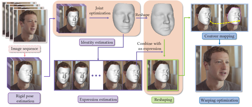
Figure 2 shows the pipeline of our method. Given a portrait image sequence, our method consists of two main stages. In the first stage (Section 4), we utilize a video-based face reconstruction approach to faithfully reconstruct high-quality face identity with stable poses and expressions. We first estimate the head pose in each frame, which is crucial to estimate a consistent identity across frames. Then we find the frames that best represent the face identity and jointly optimize a consistent face identity. Finally we estimate the face expression of each frame to achieve the whole 3D face sequence. In the second stage (Section 5), we generate reshaped faces in 3D based on the reconstruction results, then leverage deformed faces in 3D to guide the reshaped portrait video generation in 2D. We first reshape the reconstructed 3D neutral face model and combine it with facial expression and pose for each video frame. We then employ an SDF based method to construct a 2D dense mapping of the face contour before and after reshaping. A content-aware warping optimization is used to deform portrait frames according to reshaped faces in 3D, resulting in the final reshaped portrait video.
4. Video based face reconstruction
In this section, we first describe the parametric face model and the objectives that our optimization is based on. Then we elaborate how we optimize face pose, identity, and expression step by step while taking into account robustness and efficiency.
4.1. Parametric Face Model and Objectives
The parametric face model can be represented via a linear combination of identity basis vectors and expression basis vectors:
| (1) |
where is the mean face identity ( is the number of vertices of the face), is one of the identity basis vectors, and is one of the expression basis vectors. , are the identity coefficients and expression coefficients, respectively.
The parametric face model proposed by Huber et al. (2016) consists of facial identity coefficients and expression coefficients. Although this model does not express ample expressions, it is capable of representing common portrait faces.
We denote the projection operator by , which maps the -th mesh vertex to image coordinate as:
| (2) |
where and are the rotation and translation parameters of the face model, respectively. Now we present our objective energy terms based on the aforementioned parameters which will be used in the latter optimization.
Landmark energy. We denote a set of 2D facial landmark indices as ( is the number of landmarks). The first objective aims to match all 3D landmarks to their corresponding 2D landmarks after projection (assume 2D and 3D landmark indices are the same for simplicity):
| (3) |
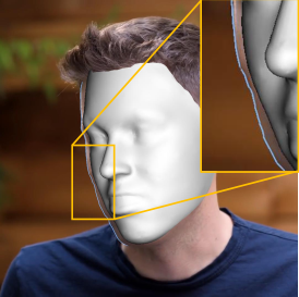
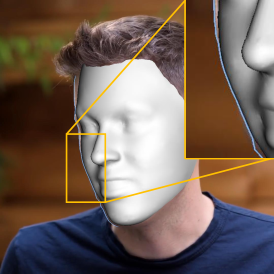
Contour energy. The part of face away from the camera is likely to have offset landmarks in 2D due to the incomplete face region induced by occlusion (see an example in Figure 8(a) near the eye). Therefore we also define a contour energy to match face boundary between 3D and 2D. Note that the boundary of the projected 3D face model will change when the pose changes, and thus it is impossible to obtain the accurate boundary. However, as our method estimates face rigid pose first (see Section 4.2), we can utilize the boundary of the approximate 3D face model obtained from the rigid pose estimation step to constrain the alignment.
Then the contour energy can be expressed as follows:
| (4) |
where is the set of indices of contour landmarks, and is the corresponding vertex’s index on the 3D face boundary.
Alignment energy. By now, we can define the alignment energy as the linear combination of landmark energy and contour energy:
| (5) |
Empirically, we set .
Prior energy. A regularization term is also defined to constrain the reconstructed face to be regular in face space:
| (6) |
where is the weight of the regularization. We empirically set as 0.4.
Temporal coherence energy. Typically the temporal coherence energy reduces the parameter difference between previous frame and current frame. The expression coherence term can be defined as:
| (7) |
Similarly, the pose coherence term can be defined as:
| (8) |
where is the parameter to balance the effect of translation and rotation. In our experiment, we set as the reciprocal of face length. Then the overall temporal coherence energy is defined as:
| (9) |
where we set in our experiments.
Dense flow energy. Inspired by Cao et al. (2018), we use optical flow to construct dense correspondences to overcome landmark detection errors. With pose parameter and expression coefficients from the previous frame, the dense flow energy is defined as:
| (10) |
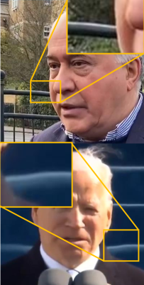
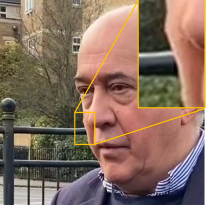
where is the motion vector. As expression change is not our main concern, we define the energy term only on face contour rather than the full face, which also reduces computational cost without affecting visual quality. However, artifacts occur when the optical flow map is inaccurate on face contour due to occlusions caused by other objects (see Figure 3 for a failure case). The change of optical flow on the face contour is mainly induced by camera movement and face pose transformations. Besides, the occluded regions may have different values on the flow map. Employing a low-frequency filter to eliminate the outliers can preserve the correct part.


4.2. Stabilized Face Tracking
Reconstructing face shape on the fly is convenient for real-time applications. However, it is hard to ensure that the identity reconstructed from the first frame is the same as that from the last frame. In contrast, joint optimization for all frames can achieve a consistent face identity but is too costly. As such, we first estimate the face pose for each frame, and then choose the consecutive frames which best represent the face identity coefficients. After that, we apply joint optimization for these frames to achieve the accurate face identity. Finally we estimate the expression coefficients of each frame to obtain the final reconstruction result. The advantage of approximating face pose first is that face poses provide stable projected face contours and face regions in 2D, which enables us to employ the contour energy and revised dense flow energy defined in Section 4.1 for identity and expression reconstruction.
4.2.1. Rigid Pose Estimation
Based on the objectives defined in Section 4.1, the pose estimation energy is defined as:
| (11) |
where we empirically set , , and . At this stage, we fix the identity parameters and expression parameters. Our extensive experiments show that such a strategy enables us to achieve more stable final results as the energy terms involving all variables may conflict with each other during the optimization.
4.2.2. Identity Estimation
It is hard to estimate the full shape of a face if only partial face is visible in the image. After pose estimation, we choose the consecutive frames whose faces are facing to the camera, and apply bundle optimization (Triggs et al., 1999) to these frames.
Based on the above and the objectives defined in Section 4.1, the identity estimation energy is defined as:
| (12) | ||||
To estimate the face identity as accurate as possible, we intentionally increase the weight of the landmark energy term . In our experiments, we set , and .
4.2.3. Expression Estimation
After shape estimation, we solve for face expressions by fixing shape coefficients. Similar to , we can define the expression energy as follows:
| (13) | ||||
where we empirically set , and . However, we apply it for all video frames.
5. Reshaping
In this section, we reshape the 3D faces reconstructed in the last section and use them to guide the generation of the reshaped portrait video. More specifically, given a reshaping parameter, we first use a linear regression model to generate the reshaped faces in each frame (Section 5.1). Then we employ image warping to deform each frame respecting the corresponding reshaped face (Section 5.2).
5.1. 3D Face Reshaping
Xiao et al. (2020) proposed a reshaping model to generate reshaped portrait images based on an estimated adjusting parameter. We extend this method from reshaping one monocular image to reshaping the whole image sequence. The reshaping model deforms the whole face by utilizing a scalar parameter as input. We denote the reshape operator as .
For a sequence of reconstructed 3D faces , where is the expression coefficients vector of the -th frame, the reshaped 3D face model is defined as the linear combination of the neutral reshaped face model and the expression coefficients :
| (14) |
where is the expression coefficients vector of the neutral face.
5.2. Consistent Video Deformation
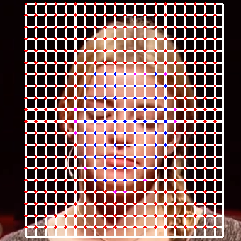
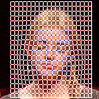
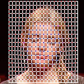
Using the reshaped 3D faces as guidance, we warp each portrait image to generate the face with the target shape in 2D while avoiding visible artifacts. We first place a uniform grid over the image as a warping proxy (see Figure 5 (a)), where denotes the 2D coordinates of the grid point on the image. Then we propose a new method to find a set of control points , which drive the image warping induced by the face deformation. Finally, we employ a least-square optimization to warp all the other grid points by minimizing the distortion of the entire grid.
Control points selection. It is straightforward to select control points directly on the 3D face model. Jain et al. (2010) selected face mesh vertices and used their 2D projections as control points. However, some control points (mesh vertices) may be occluded (or may emerge) after face deformation and projection, which can significantly affect the warped face shape on the image and cause severe artifacts. Xiao et al. (2020) utilized the closest grid points to the 2D face contour as control points. While their method works well for a single portrait, it ignores the occluded control points especially when enlarging a face. Therefore, such a method cannot ensure that the control points are still at the face contour after reshaping, which leads to noticeable inconsistent and incoherent video frames after warping.
As the original video is already continuous with the right content, after face reshaping, the control points need to be stabilized at the location that expresses the same semantic information. Hence the problem of selecting control points amounts to find a mapping between face shape and control points before and after reshaping.
SDF based selection. We propose a SDF based method to establish consistent mapping of the image contour points before and after reshaping, and then transfer the mapping to control points. The benefit of stabilized face reconstruction is that the face contour in 3D is always complete, and its 2D projection gradually changes, which can be leveraged to achieve consistent and coherent control points selection. Note that unlike in 3D, semantically accurate face contour mapping in 2D does not always exist due to possible occlusions after reshaping and projection (e.g., face boundary partly blocked by nose but not as before), thus we employ an approximate mapping in practice as follows.
We first choose all face contour pixels of the original frame and map them to the reshaped face in 2D. We find that dense mapping of all contour pixels can further reduce inconsistency compared to sparse mapping of a subset of pixels (see comparison in Figure 10 and discussion in Section 6). We use the reconstructed 3D face model to guide the dense mapping. For each contour pixel, we first unproject it to the reconstructed 3D face model, then reshape the face model and project it back to the image to get its mapped pixel. This process cannot achieve consistent contour of 3D model after reshaping (see Figure 4 (b)). Therefore, we revise the incorrect mapping (by checking if the mapped pixel lies on the reshaped face contour) based on the SDF of the original 2D face contour (see pink contour in Figure 4 (c)). More specifically, for such a contour pixel, we move it along the gradient of the SDF until it meets the mapped pixel on the reshaped face contour in 2D (boundary of the projected 3D face after reshaping). This method still has problems in extreme cases where the mapping incorrectly maps nose points to cheeks points (see the boxed-out area both in Figure 4 (a) and (c)). For such cases, we remove the incorrect mappings according to the 3D structure information of each points (see Figure 4 (d)).


Warping. Based on the dense contour mapping, we select grid points which are closest to the face contour. Then we employ moving least squares (MLS) deformation (Schaefer et al., 2006) to find the target position of guided by the dense mapping. After that, we employ a least-square optimization to other grid points while fixing the control points to minimize the overall distortion (see Figure 5). We adds the linear bending term and regularization term proposed by Shih et al. (2019):
| (15) |
| (16) |
where is the -th key point of grid , is the set of 4-way adjacent points of key point , and is the unit vector along the direction .
We only select the area surrounding the face as the target area for optimization. In order to make the optimized area blend perfectly with the non-optimized area, we fix the boundary grid points instead of adding a grid border term as in (Shih et al., 2019) to adjust the distortion in the boundary. The final energy function is:
| (17) |
We empirically set the weights as , .
6. Evaluation
In this section, we extensively evaluate the proposed method, including testing on various examples, comparing with image reshaping based method, validating our method design choices with baselines, and presenting the performance and implementation details.
6.1. Results
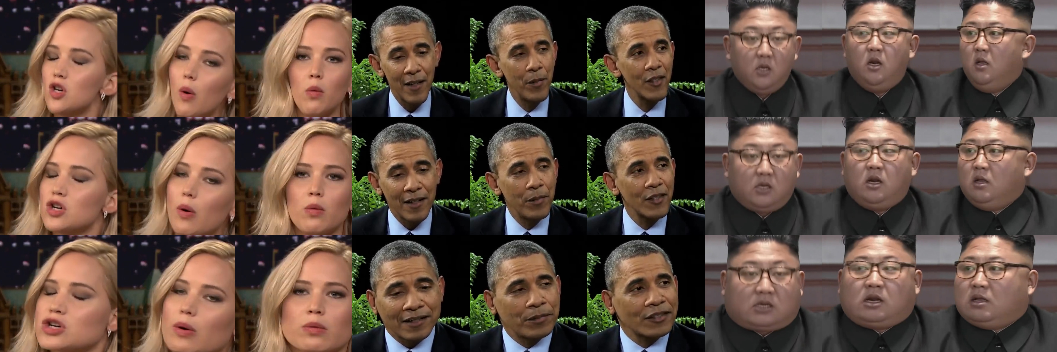
We test our method on a variety of portrait videos with different gender, hairstyle, skin color, etc. Figure 1 shows some sampled video frames generated by our method. It can be seen that our method can successfully reshape portraits without introducing visual artifacts. By changing the parameter , we can continuously adjust the portrait shape (either thinner or rounder) for potential face retouching and exaggeration applications. More examples and full video sequences can be found in the supplemental video.


6.2. Comparison
As there is no prior work on parametric reshaping of portraits in videos, we take the parametric reshaping method of portrait images (Xiao et al., 2020) as the baseline for comparison. Given a portrait video footage, for a frame shown in Figure 6(a), as the nose occludes the side face of the portrait, the method of Xiao et al. (2020) will produce obvious artifacts (see Figure 6(b)) near the tip of the nose because of their sparse mapping, which is successfully solved using our dense mapping method (see Figure 6(c)) with the same reshaping parameter. Moreover, their method cannot generate smooth and coherent reshaping portrait video results. Please refer to the accompanying video for side-by-side comparison. The results show that our approach can robustly produce coherent reshaped portrait videos while the image-based method can easily lead to noticeable flickering artifacts.
6.3. Ablation studies
We also verify the design choices of our method by validating its two main stages, i.e., face reconstruction and video reshaping, respectively. We show the effectiveness of our design choices by comparing them with other baselines.
6.3.1. Face reconstruction
We first evaluate the effectiveness of our new dense flow energy. We compare our result to the result without using dense flow energy, and the result using dense flow energy but defined on the entire face.
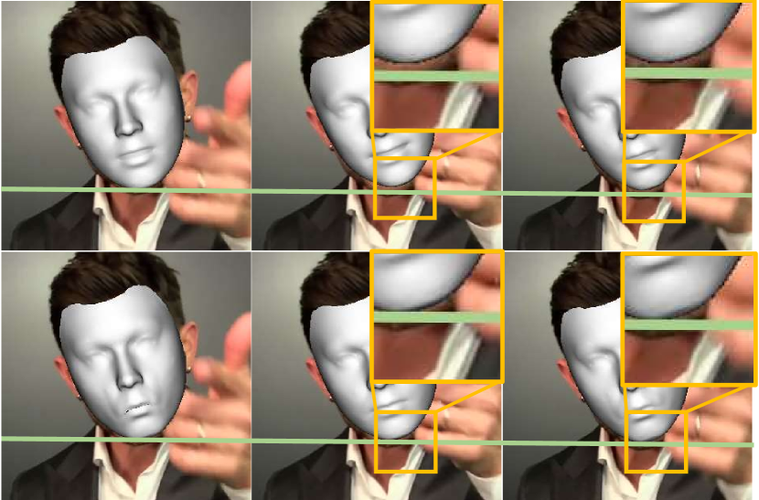
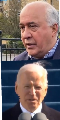
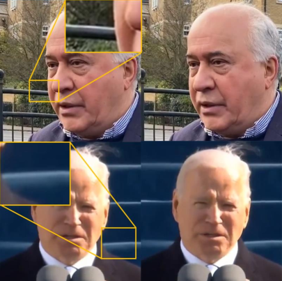
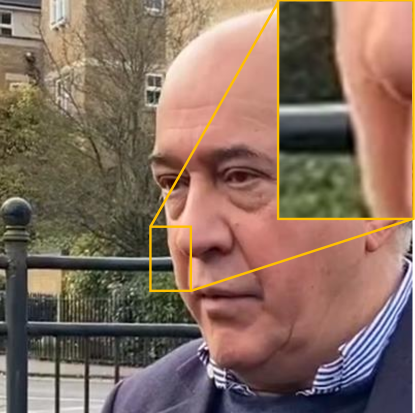
In most cases, using dense flow energy helps to produce visually pleasing results. The stability difference between using dense flow energy or not is better to be seen in video sequence. It is worth noting that the dense flow energy can effectively suppress the effects of jittering landmarks near the face contour, but cannot eliminate them completely. If the landmarks themselves are jittering, the estimated transformations cannot be very smooth. Figure 7 shows the problematic case without discarding vertices inside the wrong regions of the flow map. The handshakes near the face cause wrong motion directions in the flow map, resulting in instability head transformations.
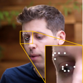
We then evaluate the contour energy which restricts the face model to align with the 2D face contour. It is more difficult to detect the landmarks of the side face compared to the frontal one. We found that the detected landmarks tend to have offset at the side when they are far away from the camera, leading to a poor alignment between the face model and its 2D face contour. For example, the landmarks near the eye have offset as shown in Figure 8(a). Figure 8(b) and Figure 8(c) show results without and with the contour energy, respectively. Although both results have similar eye locations, the one using contour energy achieves better alignment. For an image sequence, aligned contours result in continuous and stable face transformations.
6.3.2. Video reshaping
We first perform comparisons to demonstrate that our approach which combines MLS and grid optimization is meaningful and effective. Figure 9 shows the comparison with the MLS-only approach, the optimization-only approach, and our approach. It shows that the grid optimization is effective in correcting background distortion. And the MLS approach ensures the coherence of the face boundaries and the video stability. Besides, optimization-only approach requires a higher grid resolution (up to four times) to achieve similar results, but still has incoherent face boundary.
We then perform comparisons to prove that using SDF based dense boundary mapping is effective for preserving face reshaping consistency and the stability of the video. Figure 10(a) shows the case of not fixing face contour points, where only the feature points used for reshaping are exploited as fixed control points. This method does not reflect enough information about the reshaping, thus the obtained results do not coincide with the projection of the 3D model after reshaping. Figure 10(b) shows the case of only using a set of sparse grid points to represent the face boundary. Here we select suitable initial grid points coincided with the face contour as fixed control points. Two more energy terms are introduced in Eqn. 17 in order to obtain reasonable results (see Appendix for details).
The results are better than other baselines. In the case of a small degree of face reshaping, the defects are almost invisible and it can generally achieve video coherence. However, if the face is largely deformed, as shown in Figure 10(b), protrusions and gaps in the face boundary appear and they may affect video continuity. Also, the time consumed by this method is significantly increased.
Figure 11 shows the result of selecting control points based on dense mapping from SDF without using the 3D model information. This performs well in most cases, but has problem when the nose contour affects the face contour.
6.4. Implementation Details
We use the optical flow algorithm provided by OpenCV to extract the motion map, and use Gaussian sampling to get the motion value of each projected face vertex instead of bilinear interpolation to avoid local minima and obtain smoother results (Ren et al., 2019). We perform facial landmark detection as proposed in (Bulat and Tzimiropoulos, 2017). We use Ceres (Agarwal et al., 2012) to solve optimization in Section 4 and Section 5. For image warping, we set the grid dimension to for all of our results.
Our implementation is on a desktop PC with AMD Ryzen 9 3950X CPU and 32GB memory. In the face reconstruction stage, pose estimation takes 120ms per frame on average, identity estimation computes only once and takes 321ms, and the expression estimation takes 150ms per frame. In the video reshaping stage, the 3D face deformation takes 160ms at the beginning. Image warping takes 266ms per frame, where MLS based image deformation and grid optimization take 71ms and 74ms, respectively.
The videos we used are all downloaded from public datasets or Youtube websites. The sources of each video are listed in Appendix.
7. Discussions
All of our results show plausible reshaping without visible artifacts. However, our method still has some limitations. First, visual distortion may appear in the surrounding regions close to the face when large shape deformation is employed. Video inpainting methods (Kim et al., 2019) could be employed on background regions to further improve the results. Second, we note the fact that wrinkles will reduce and a double chin will appear when gaining weight on the face; while wrinkles will increase and a double chin will diminish when losing weight. But similar to reshaping portrait images (Xiao et al., 2020), our approach cannot deal with such changes. Further, our current approach is fully unsupervised, which means it does not require any customized face priors, thus it can be directly used to process portrait videos in the wild. On the other hand, with the help of more pre-knowledge such as face shape, our method can be consequently adapted and accelerated to reshape portrait videos on the fly.
8. Conclusions
We have presented the first method to reshape portraits in a video. Our video-based face reconstruction method is able to eliminate the effects of jittering landmarks and incorrect flow map, resulting in a steady 3D face model sequence with accurate identities and smooth transformations. We achieve a consistent video deformation by aligning the face model sequence with the face contours of the image sequence. We employ an SDF based approach to produce a dense and smooth mapping from the initial face to the reshaped face, which effectively minimizes the warping distortion and avoids visual artifacts after video reshaping. Extensive evaluations and comparisons demonstrate that our method can generate high-quality portrait video reshaping results.
Acknowledgements.
Xiaogang Jin was supported by the National Natural Science Foundation of China (Grant No. 61972344), the Key Research and Development Program of Zhejiang Province (Grant no. 2018C03055), and the Ningbo Major Special Projects of the “Science and Technology Innovation 2025” (Grant No. 2020Z007). Yong-Liang Yang was partly supported by RCUK grant CAMERA (EP/M023281/1, EP/T022523/1), and a gift from Adobe.References
- (1)
- Agarwal et al. (2012) Sameer Agarwal, Keir Mierle, and Others. 2012. Ceres Solver. http://ceres-solver.org.
- Blanz and Vetter (1999) Volker Blanz and Thomas Vetter. 1999. A morphable model for the synthesis of 3D faces. In the 26th Annual Conference on Computer Graphics and Interactive Techniques. ACM, 187–194.
- Booth et al. (2017) James Booth, Epameinondas Antonakos, Stylianos Ploumpis, George Trigeorgis, Yannis Panagakis, and Stefanos Zafeiriou. 2017. 3D Face Morphable Models ”In-the-Wild”. In IEEE Conference on Computer Vision and Pattern Recognition (CVPR). 5464–5473.
- Bulat and Tzimiropoulos (2017) Adrian Bulat and Georgios Tzimiropoulos. 2017. How Far are We from Solving the 2D & 3D Face Alignment Problem? (and a Dataset of 230, 000 3D Facial Landmarks). In IEEE International Conference on Computer Vision (ICCV). 1021–1030.
- Cao et al. (2018) Chen Cao, Menglei Chai, Oliver J. Woodford, and Linjie Luo. 2018. Stabilized Real-time Face Tracking via a Learned Dynamic Rigidity Prior. ACM Transactions on Graphics (TOG) 37, 6 (2018), 1–11.
- Chen et al. (2020) Renwang Chen, Xuanhong Chen, Bingbing Ni, and Yanhao Ge. 2020. SimSwap: An Efficient Framework For High Fidelity Face Swapping. In Proceedings of the 28th ACM International Conference on Multimedia. 2003–2011.
- Chen et al. (2013) Tao Chen, Jun-Yan Zhu, Ariel Shamir, and Shi-Min Hu. 2013. Motion-Aware Gradient Domain Video Composition. IEEE Transactions on Image Processing 22, 7 (2013), 2532–2544.
- Egger et al. (2020) Bernhard Egger, William A. P. Smith, Ayush Tewari, Stefanie Wuhrer, Michael Zollhöfer, Thabo Beeler, Florian Bernard, Timo Bolkart, Adam Kortylewski, Sami Romdhani, Christian Theobalt, Volker Blanz, and Thomas Vetter. 2020. 3D Morphable Face Models - Past, Present, and Future. ACM Transactions on Graphics (TOG) 39, 5 (2020), 157:1–157:38.
- Huber et al. (2016) Patrik Huber, Guosheng Hu, Rafael Tena, Pouria Mortazavian, Wollem P. Koppen, William Christmas, Matthias Rätsch, and Josef Kittler. 2016. A Multiresolution 3D Morphable Face Model and Fitting Framework. In the 11th Joint Conference on Computer Vision, Imaging and Computer Graphics Theory and Applications (VISIGRAPP), Vol. 4. 79–86.
- Jain et al. (2010) Arjun Jain, Thorsten Thormählen, Hans-Peter Seidel, and Christian Theobalt. 2010. MovieReshape: tracking and reshaping of humans in videos. ACM Transactions on Graphics (TOG) 29, 6 (2010), 148.
- Kaufmann et al. (2013) Peter Kaufmann, Oliver Wang, Alexander Sorkine-Hornung, Olga Sorkine-Hornung, Aljoscha Smolic, and Markus H. Gross. 2013. Finite Element Image Warping. Computer Graphics Forum 32, 2 (2013), 31–39.
- Kim et al. (2019) Dahun Kim, Sanghyun Woo, Joon-Young Lee, and In So Kweon. 2019. Deep Video Inpainting. In IEEE Conference on Computer Vision and Pattern Recognition (CVPR). 5792–5801.
- Lewis et al. (2014) John P. Lewis, Ken Anjyo, Taehyun Rhee, Mengjie Zhang, Frédéric H. Pighin, and Zhigang Deng. 2014. Practice and Theory of Blendshape Facial Models. In the 35th Annual Conference of the European Association for Computer Graphics. 199–218.
- Leyvand et al. (2008) Tommer Leyvand, Daniel Cohen-Or, Gideon Dror, and Dani Lischinski. 2008. Data-Driven Enhancement of Facial Attractiveness. ACM Transactions on Graphics (TOG) 27, 3 (2008), 38.
- Li et al. (2020) Ruilong Li, Karl Bladin, Yajie Zhao, Chinmay Chinara, Owen Ingraham, Pengda Xiang, Xinglei Ren, Pratusha Prasad, Bipin Kishore, Jun Xing, and Hao Li. 2020. Learning Formation of Physically-Based Face Attributes. In 2020 IEEE/CVF Conference on Computer Vision and Pattern Recognition (CVPR). IEEE, Seattle, WA, USA, 3407–3416.
- Nagano et al. (2019) Koki Nagano, Jaewoo Seo, Jun Xing, Lingyu Wei, Zimo Li, Shunsuke Saito, Aviral Agarwal, Jens Fursund, and Hao Li. 2019. paGAN: real-time avatars using dynamic textures. ACM Transactions on Graphics 37 (2019), 1–12.
- Ren et al. (2019) Yurui Ren, Xiaoming Yu, Ruonan Zhang, Thomas H. Li, Shan Liu, and Ge Li. 2019. StructureFlow: Image Inpainting via Structure-Aware Appearance Flow. In IEEE/CVF International Conference on Computer Vision (ICCV). 181–190.
- Schaefer et al. (2006) Scott Schaefer, Travis McPhail, and Joe D. Warren. 2006. Image deformation using moving least squares. Vol. 25. 533–540.
- Shih et al. (2019) Yi-Chang Shih, Wei-Sheng Lai, and Chia-Kai Liang. 2019. Distortion-Free Wide-Angle Portraits on Camera Phones. ACM Transactions on Graphics (TOG) 38, 4 (2019), 61:1–61:12.
- Shih et al. (2014) Yi-Chang Shih, Sylvain Paris, Connelly Barnes, William T. Freeman, and Frédo Durand. 2014. Style Transfer for Headshot Portraits. ACM Transactions on Graphics (TOG) 33, 4 (2014), 148:1–148:14.
- Tewari et al. (2020) Ayush Tewari, Mohamed Elgharib, Mallikarjun B R, Florian Bernard, Hans-Peter Seidel, Patrick Pérez, Michael Zollhöfer, and Christian Theobalt. 2020. PIE: portrait image embedding for semantic control. ACM Transactions on Graphics 39, 6 (2020), 1–14.
- Thies et al. (2015) Justus Thies, Michael Zollhöfer, Matthias Nießner, Levi Valgaerts, Marc Stamminger, and Christian Theobalt. 2015. Real-time Expression Transfer for Facial Reenactment. ACM Transactions on Graphics (TOG) 34, 6 (2015), 183:1–183:14.
- Thies et al. (2016) Justus Thies, Michael Zollhöfer, Marc Stamminger, Christian Theobalt, and Matthias Nießner. 2016. Face2Face: Real-Time Face Capture and Reenactment of RGB Videos. In IEEE Conference on Computer Vision and Pattern Recognition (CVPR). 2387–2395.
- Tran et al. (2019) Luan Tran, Feng Liu, and Xiaoming Liu. 2019. Towards High-Fidelity Nonlinear 3D Face Morphable Model. In IEEE Conference on Computer Vision and Pattern Recognition (CVPR). 1126–1135.
- Tran and Liu (2018) Luan Tran and Xiaoming Liu. 2018. Nonlinear 3D Face Morphable Model. In IEEE Conference on Computer Vision and Pattern Recognition (CVPR). 7346–7355.
- Triggs et al. (1999) Bill Triggs, Philip F. McLauchlan, Richard I. Hartley, and Andrew W. Fitzgibbon. 1999. Bundle Adjustment - A Modern Synthesis. In International Workshop on Vision Algorithms, Vol. 1883. 298–372.
- Xiao et al. (2020) Qinjie Xiao, Xiangjun Tang, You Wu, Leyang Jin, Yong-Liang Yang, and Xiaogang Jin. 2020. Deep Shapely Portraits. In MM ’20: The 28th ACM International Conference on Multimedia. 1800–1808.
- Zeng et al. (2020) Dan Zeng, Han Liu, Hui Lin, and Shiming Ge. 2020. Talking Face Generation with Expression-Tailored Generative Adversarial Network. In Proceedings of the 28th ACM International Conference on Multimedia (MM ’20). 1716–1724.
- Zhao et al. (2018) Haiming Zhao, Xiaogang Jin, Xiaojian Huang, Menglei Chai, and Kun Zhou. 2018. Parametric Reshaping of Portrait Images for Weight-change. IEEE Computer Graphics and Applications 38, 1 (2018), 77–90.
- Zollhöfer et al. (2018) Michael Zollhöfer, Justus Thies, Pablo Garrido, Derek Bradley, Thabo Beeler, Patrick Pérez, Marc Stamminger, Matthias Nießner, and Christian Theobalt. 2018. State of the Art on Monocular 3D Face Reconstruction, Tracking, and Applications. Computer Graphics Forum 37, 2 (2018), 523–550.