t60pt
Wireless LAN sensing with smart antennas
Abstract
The paper targets the problem of human motion detection using Wireless Local Area Network devices (WiFi) equipped with pattern reconfigurable antennas. Motion sensing is obtained by monitoring the body-induced alterations of the ambient WiFi signals originated from smart antennas supporting the beam-steering technology, thus allowing to channelize the antenna radiation pattern to pre-defined spots of interest. We first discuss signal and Channel State Information (CSI) processing and sanitization. Next, we describe the motion detection algorithm based on Angle-of-Arrival (AoA) monitoring. Proposed algorithms are validated experimentally inside a large size smart home environment.
Index Terms:
smart antennas, beam-steering technology, motion detection, WLAN sensing, passive localization.I Introduction
Wireless Local Area Network (WLAN) sensing (also known as WiFi sensing) targets the integration of novel environmental recognition capabilities into next generation WiFi and cellular machine-type communication radio interfaces [1, 2, 3]. The Channel State Information (CSI) of ambient Wi-Fi signals, optimized for communication, are processed in real time to detect changes of the environment, such as human body or object motions, activities, gestures as well as bio metric measurements [4]. Radio signals are perturbed by objects, body movements, and changes in the surroundings, as a result of the propagation of ElectroMagnetic (EM) waves [5]. Hence, in addition to transporting modulated information, WiFi signals can be re-used for sounding the environment in the form of a 2D/3D views of traversed objects by the EM wavefield.
Presently, the joint utilization of radio resources for communication and sensing, is actively discussed in research, standardization and industry. Several methods for passive radio sensing have been studied [2, 3, 5] based on simple radio-frequency (RF) hardware and power only measurements in the form of Received Signal Strength (RSS) values. Recently, more complex methods based on Channel State Information (CSI) matched with multi-antenna orthogonal frequency division multiplexing (MIMO-OFDM) devices have been shown to provide improved detection and recognition accuracy [6, 7, 8]. Antenna arrays can be also exploited [9] to extract Angle-of-Arrival (AoA) information (i.e., beam-forming) and improve both spatial accuracy and resolution.
Motion and intrusion detection are the most used and studied application of WLAN sensing. The main approaches towards radio sensing are both data and model driven as human behaviors and movements can be modelled through a training stage [10, 11] or using statistical/EM tools [12, 5]. Body motions cause abnormalities in radio propagation and can be detected using several methods. For example, model-based algorithms, e.g., threshold-based detection, and simple machine learning based algorithms, e.g., Support Vector Machine (SVM), are widely used. First studies on baseband CSI processing dates back to [13]: the DeMan system is a unified scheme for non-invasive detection of moving and stationary human on commodity WiFi devices. DeMan takes advantages of both amplitude and phase eigenvalues information of CSI to detect moving targets and provides a detection accuracy of about % for both moving and stationary people moving in controlled indoor environments. MoSense [10] is a radio frequency (RF) based device-free motion detection system designed to deliver a reliable and transparent detection service in the real-time. Designed for MIMO-OFDM radio interfaces, the implementation of MoSense tackles the problem of optimal selection of CSI subcarriers, to better capture the impact of motions from the noisy channel samples. The features used for motion detection are the phase difference from CSI signals received across two antennas, which lead to an accuracy of %. Hang et al. in [11] designed and implemented WiSH, a real-time system for contactless human detection that can be implemented on resource limited devices with limited computational power and low CSI sampling rate (20 Hz).
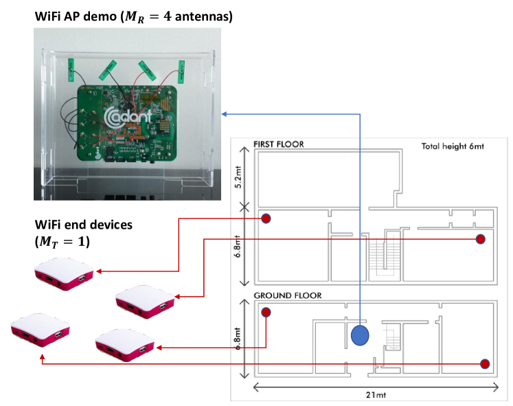
The integration of radio sensing algorithms with smart-antenna systems is a new paradigm that will become a key enabling technology for next generation environment-aware radio communication system. Building on the results from initial studies in [14], the paper addresses the technology transfer and validation of radio sensing as integrated within a WiFi radio interface compliant with the IEEE 802.11ax (WiFi6) standard and equipped with smart antennas supporting the beam-steering technology [15]. Pattern reconfigurable antennas allow to channelize the antenna radiation pattern to pre-defined areas of interest [14, 15]. The paper proposes CSI signal pre–processing tools required to effectively transform beam-steering into a reliable sensing technology. In fact, adapting the radiation pattern of individual antennas provides more spatial views of the environment and hence promises unprecedented sensing accuracy as well as it paves the way to joint sensing and communication co-designs. In particular, we propose a beam-space processing model and an AoA estimation framework based on Principal Component Analysis (PCA) and MUltiple SIgnal Classification (MUSIC). Several validation tests have been carried out inside a smart home environment, namely a large test house of approximately 300 sqm (see Fig. 1), with the purpose of: a) developing an enhanced WiFi Access Point (AP) gateway for residential use with improved connectivity, and b) providing, through the same residential WiFi test network, a motion detection service to support several application verticals such as intrusion detection and smart living.
The paper is organized as follows. Sect. II describes the CSI modelling and processing of AoA including the necessary adaptations to the proposed smart antenna system as well as the main implementation choices for AoA estimation, CSI feature processing and motion detection. Sect. III describes the case study and the results obtained in the test house environment: according to this test setup, system performances, namely accuracy, false alarm,miss detection probability and robustness, are verified considering two AP deployment cases. Sect. IV draws some conclusions.
II CSI modelling and AoA processing
We analyze the uplink of a typical WiFi MIMO-OFDM communication system [8, 16] consisting of radio devices (WiFi6 end devices) equipped with antennas and communicating with one WiFi access point (AP) gateway equipped with antennas with spacing . In line with [14], we resort to a practical case where the AP gateway is equipped with a smart antenna system and supports beam-steering functions [17], while the WiFi6 end devices are equipped with a single antenna, . We consider the problem of device-free target motion detection inside an indoor environment consisting of multiple rooms and different subjects. Body motions are detected by inspection and real-time analysis of the CSI response that is observed at discrete time instants of consecutive received WiFi PHY Protocol Data Unit (PPDU) frames.
The WiFi signal from the end device typically reflects off multiple objects (around indoor reflectors[18]) when approaching the AP. Considering that the presence of the subject moving in the environment modifies the AoA paths, and that the number of antennas at the AP are limited, the MUSIC algorithm is typically adopted [9, 19] to disentangle the multipath components and estimate the AoA of the dominant propagation paths. The received CSI vector at the AP antenna array over one pilot subcarrier , with carrier frequency , is generally obtained by the superposition of signals due to all the paths. Considering an OFDM frame structure with pilots (), dominant reflections/propagation paths () with AoA and the corresponding complex attenuation , it is
| (1) |
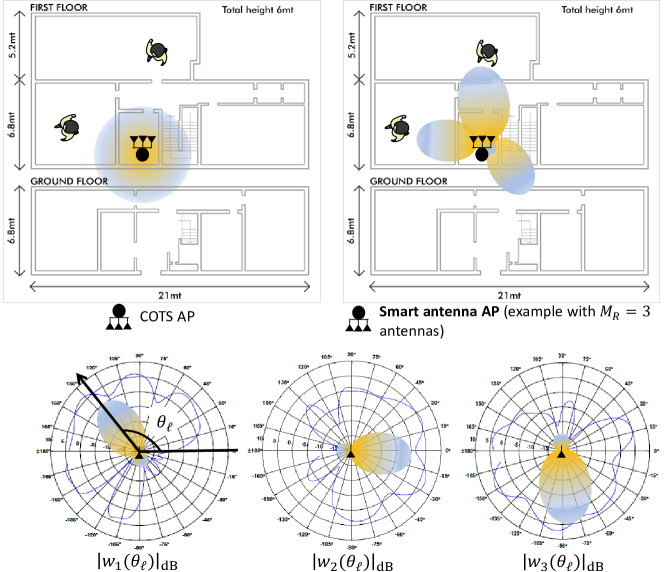
where the steering vectors model the phase shifts at the antenna array [19] ( is the light speed), while is the Hadamard (element-wise) product with the beam pattern vectors that collects the corresponding complex valued antenna responses for the considered AoA , according to the chosen antenna beam pattern. Real beampattern examples are shown in Fig. 2. Assuming that the antenna response patterns do not change across closely spaced subcarriers [9, 18], the CSI matrix at time is
| (2) |
with , and, similarly, the beam pattern terms . Finally contains the corresponding complex fading attenuations at time : notice that we assume that AoAs and beam patterns are stationary for a number of consecutive PPDU frames.
Considering now the CSI that is measured/observed by the receiver antennas at time ,
| (3) |
with the superimposed AWGN noise , a PCA-based algorithm is adopted for the eigenstructure analysis of the correlation matrix . Keeping into account the beam-steering process, we define with , so that
| (4) |
where is defined as and is the AWGN noise power. The dominant AoAs (i.e., corresponding to the signal subspace) correspond to the highest peaks of the so-called spatial spectrum [9]111We assume that the vectors are still mutually orthogonal and serve as basis for the PCA signal subspace, as required by the PCA-based analysis.
| (5) |
with the eigenvectors of corresponding to the smallest eigenvalues (i.e., the noise subspace). Notice that is estimated by maximum likelihood over consecutive PPDU frames. The resulting dominant components in (1) might be generally different from the true ones as the result of the beamsteering process, as ; however, in what follows, we show that they can be used as an effective subspace basis for motion detection. In the example of Fig. 1, an AP device equipped with electronically steerable antennas measures the PHY layer CSI over pilot subcarriers: the correlation matrix is obtained from consecutive frames, corresponding to ms interval. Frames are transmitted by an end device device (Raspberry PI 4) equipped with standard, vertically polarized omnidirectional antenna. For the purpose of motion detection, we detect and track dominant components.
II-A Phase information pre-processing and sanitization
Real phase measurements are affected by many key factors, of which the most important are the Sampling Time Offset (STO) and the Sampling Frequency Offset (SFO). These factors make raw CSI measurements on commercial WiFi devices extremely noisy. For example, the STO brings out extra delay in addition to the signal propagation time of the interested environment. This additional time delay results in random phase offset that affects the CSI readings, which in turn contaminates the true phase shifts. The SFO affects the sampling time offset from packet to packet thus adding noise to the phase estimates across packets. Therefore, it is necessary to clean up raw phase measurements before performing the AoA estimation. The CSI phase pre-processing is divided in two steps: unwrap and sanitization.
The first step is the unwrapping of the CSI phase measurement, which comes out wrapped in the interval from the AP CSI extractor tool: the unwrapping process corresponds to the correction of the actual phase by a multiple of [7]. STO adds a constant offset to the Time of Flight (ToF) estimates of all paths: this additional delay manifests itself as a linear frequency term in the phase response of the channel. The random phase offset at the -th subcarrier is therefore , where denotes the time delay due to the STO and KHz represents the frequency interval between the adjacent subcarriers. According to [7], a linear regression is adopted to estimate the STO and random phase offset from the unwrapped phase observed on the subcarrier and the antenna as
| (6) |
The calibrated phase response can be corrected (sanitized) as . A weighted moving average has been also applied on received CSI amplitude considering consecutive frames.
II-B AoA based motion detection
The approach we followed is to detect and classify the variations of the estimated dominant signals AoA (5) as these are indicative of the subject presence as moving in the environment. In case of motion, CSI perturbations might affect one or all the dominant AoAs: in line with EM modelling of body-induced fading [12], this perturbation is higher when the movement occurs close to the WiFi end device or the AP. After the CSI pre-processing and phase sanitization, we apply the AoA estimation using the PCA-based method previously described. Considering the beam-steering process, the estimated dominant AoAs are not coherent with the real direction of the signals. In order to solve this issue, a phase calibration is implemented during the initial system warm-up, which correct the phase differences among each antenna element. Phase calibration is a one-time process and must be carried out before every installation. Another limitation is that when the movement happen behind a sensor, it barely affects the AoAs, which can lead to a missed alarm event. For such cases, optimal deployment of WiFi end devices is advised. In the following tests, we extract and monitor dominant AoAs (although up to paths might be resolvable) to maximize the system robustness: these monitored angles are always detected, or with high probability, as they typically correspond to the main path, i.e., the Line-of-Sight (LOS) of near LOS path, and the main reflected path (e.g., caused by relevant obstacles). Finally, AoA resolution improvements are implemented according to [19] which remove the coherence among signals.
II-C CSI features for motion detection
Besides the AoA estimates, other signal features can be extracted from the CSI and the Received Signal Strength (RSS) data [8]. In particular, we focus below on several RSS statistical metrics (average and standard deviation) evaluated over consecutive WiFi frames, the time-frequency correlation of CSI matrix and a measure of CSI phase changes. All the features have been extracted and analyzed in order to understand which of them are more sensible and reliable when a motion event occurs. The proposed decision process monitors both the dominant AoAs, as described in the previous section, and the above mentioned metrics. The approach we followed is to select the best pool of features for our decision process, and analyse advantages, disadvantages and limitations of these choices. Notice that all the proposed features compare the CSI/RSS samples over two adjacent time intervals, and are expected to be less dependent on the specific environment, thus simplifying the calibration of the motion detection system during the system warm-up.
RSS: average and standard deviation. They corresponds to the first and second moment extracted from consecutive RSS obtained from the corresponding PPDU frames. As analyzed below and also verified in [2], we found out that the variance is way more accurate and sensitive than the average value. Instead of using the RSS average value (in dB) at frame , namely , we replace it with the relative measure that considers the temporal difference of the RSS observed over two adjacent WiFi frames, as follows: .
CSI: time and frequency domain correlation. This feature exploits the correlation of CSI amplitude in both time and frequency domains [11]. Time and frequency domain correlation decreases in the presence of moving entities [11]: to leverage the correlation in both domains, we adopt the Motion Indicator term as defined in [11] (Algorithm 1).
CSI: phase deviation. It monitors the fluctuations in the phase information as induced by body movements. In particular we use the short-term averaged variance ratio metric defined for each antenna as: , namely the ratio between the normalized (w.r.t. average) phase deviation observed in the time interval and the one observed in .
Evaluation of the aforementioned features with respect to motion detection is based on Support Vector Machine (SVM) techniques. In particular, the SVM weights are trained to classify body motions using data collected in different environments and AP deployments with respect to the validation set (see Sect. III). In the following section, we also compare the accuracy of each individual feature to highlight their advantages/limitations.
![[Uncaptioned image]](/html/2205.00973/assets/x4.png)
![[Uncaptioned image]](/html/2205.00973/assets/x5.png)
III Case study in a test house environment
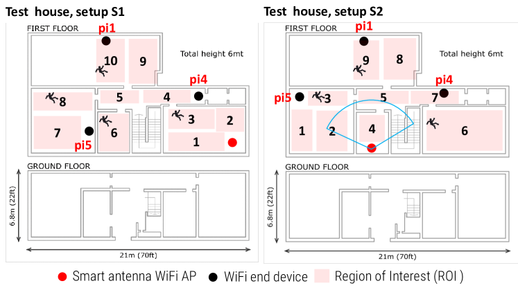
In the proposed case study, depicted in Fig. 3, we deployed unmodified WiFi devices (namely, and ) equipped with antennas each and one WiFi AP gateway with smart antennas [15, 17] inside an instrumented smart-space environment. The antenna module has inter-element spacing of cm at GHz while the AP device CPU is based on the IPQ8072A Quad Core ARM Cortex A53 System on Chip (SoC) working at 2.2GHz that supports WiFi 11.ax communications. HW specifications and data sheets are available online [20]. The proposed application case study is meant to design a system that provides augmented sensing functions for real-time motion detection of a subject located in different areas, namely the Region Of Interest (ROIs) indicated in Fig. 3 for both setups S1 and S2. Setups are characterized by different locations of the WiFi end device pi5 and the WiFi AP gateway. To assess the robustness of the detection process, the approach we followed is to train the system by collecting data from one of the two setups and then validate the accuracy of the motion detection system using data from the other setup. With respect to data collection and processing, the AP serves as an edge node not only for CSI data collection, but also for AoA and feature processing. In the proposed settings, the evaluation of the features through SVM is implemented on a remote PC: the CSI features are moved/transmitted by using JSON (Java Script Object Notation) serialization and the MQTT publisher/subscriber transport service [21].
In the Tab. I, we compare the motion detection accuracy using selected CSI features as defined in Sect. 2. In particular, the AoA estimation is based on the algorithm described in Sect. II: we monitor dominant paths, while a motion detection indicator is issued when a change is detected. Monitoring the dominant paths (AoA#1, AoA#2) separately gives much higher accuracy than average RSS and time-frequency correlation. The optimized pool of features should therefore include both AoAs and RSS standard deviation. For the selected training and validation setup combinations, in Tab. II, we analyzed the missed detection, the false alarm probability and the average motion detection accuracy. For each considered case, we reported the corresponding setup (S1 or S2, or both) and the ROIs occupied by the subject when training the SVM tool and validating the motion detection performance, respectively. As shown in this table, training the SVM model for the same setup (S) used during the system validation, but different ROIs, leads to high accuracy, as expected (% on average). On the other hand, training and validating over different setups and ROIs might lead to significant accuracy drops, down to % in some cases. For example, training in ROI 3 (setup S1) and validating motion performance in ROI 4 gives low accuracy which is coherent with the position in which the movement has been made with respect to the WiFi path between the end device and the WiFi AP. For such cases, it is advisable to train the model using multiple ROIs, i.e. multiple rooms, to enrich the number of examples in the training set. Finally, training the SVM model using examples obtained from different WiFi AP deployments (setups S1 and S2) gives the best accuracy performance (%).
IV Concluding remarks
The paper introduced the use of the beam-steering antenna technology for passive sensing and detection of body motion events using ambient WiFi signals. Pattern reconfigurable antennas can channelize the radiation energy to improve the coverage over selected areas and are thus helpful for environment-aware joint sensing and communication applications. A model for beam-space processing has been proposed and applied to estimate the dominant propagation paths (AoA) using a PCA-based modified MUSIC algorithm. Validation tests have been carried out inside a smart home environment with the purpose of verifying the robustness of the motion detection system inside a representative residential WiFi network. As future development, the possibility of controlling the antenna steering process on a physical frame basis will be investigated as a new opportunity for improving AoA monitoring for sensing.
V Acknowledgements
This research work has been supported by the CHIST-ERA EU project RadioSense (Wireless Big-Data Augmented Smart Industry) under grant CHIST-ERA-17-BDSI-005.
References
- [1] M. Youssef, et al., “Challenges: device-free passive localization for wireless environments,” Proc. of the 13th annual ACM international conference on Mobile computing and networking (MobiCom ’07), New York, NY, USA, 222–229, 2007.
- [2] J. Wilson et al., Radio tomographic imaging with wireless networks,” IEEE Trans. on Mobile Comp. , vol. 9, no. 5, pp. 621-632, 2010.
- [3] D. Wu, et al., “Device-Free WiFi Human Sensing: From Pattern-Based to Model-Based Approaches,” IEEE Communications Magazine, vol. 55, no. 10, pp. 91–97, Oct 2017.
- [4] B. Yu et al., “WiFi-Sleep: Sleep Stage Monitoring Using Commodity Wi-Fi Devices,” IEEE Internet of Things Journal, vol. 8, no. 18, pp. 13900–13913, 15 Sept.15, 2021.
- [5] S. Savazzi, et al. “On the use of stray wireless signals for sensing: A look beyond 5G for the next generation industry,” Computer, vol. 52, no. 7, pp. 25-36, July 2019.
- [6] S. Shi, et al., “Accurate Location Tracking From CSI-Based Passive Device-Free Probabilistic Fingerprinting,” IEEE Trans. on Vehicular Tech., vol. 67, no. 6, pp. 5217–5230, June 2018.
- [7] L. Zhang, et al., “DeFi: Robust Training-Free Device-Free Wireless Localization With WiFi,” IEEE Transactions on Vehicular Technology, vol. 67, no. 9, pp. 8822–8831, Sept. 2018.
- [8] S. Kianoush, et al., “Leveraging MIMO-OFDM radio signals for device-free occupancy inference: system design and experiments,” EURASIP Journal on Advances in Signal Processing, no. 44, pp. 1–19, 2018.
- [9] X. Li, et al., “Dynamic-MUSIC: accurate device-free indoor localization,” Proc. of the ACM UbiComp, pp. 196–207, 2016.
- [10] Y. Gu, et al., “MoSense: An RF-Based Motion Detection System via Off-the-Shelf WiFi Devices,” IEEE Internet of Things Journal, vol. 4, no. 6, pp. 2326–2341, Dec. 2017.
- [11] T. Hang, et al., “WiSH: WiFi-based real-time human detection,” Tsinghua Science and Tech., vol. 24, no. 5, pp. 615–629, Oct. 2019.
- [12] V. Rampa, et al., “Electromagnetic models for passive detection and localization of multiple bodies,” IEEE Transactions on Antennas and Propagation, 2021. doi: 10.1109/TAP.2021.3111405
- [13] C. Wu, et al., “Non-Invasive Detection of Moving and Stationary Human With WiFi,” IEEE Journal on Selected Areas in Communications, vol. 33, no. 11, pp. 2329–2342, Nov. 20154.
- [14] S. Savazzi, et al., “Pattern reconfigurable antennas for passive motion detection: WiFi test-bed and first studies,” Proc. of IEEE 30th Annual International Symposium on Personal, Indoor and Mobile Radio Communications (PIMRC), pp. 1-6, 2019.
- [15] D. Piazza, et al., “Design and Evaluation of a Reconfigurable Antenna Array for MIMO Systems,” IEEE Trans. on Ant. and Prop., vol. 56, no. 3, pp. 869–881, March 2008.
- [16] E. Khorov, et al., “A Tutorial on IEEE 802.11ax High Efficiency WLANs,” IEEE Communications Surveys & Tutorials, vol. 21, no. 1, pp. 197–216, 2019.
- [17] D. Piazza, et al., “Reconfigurable antenna apparatus ”, US Patent no. US9263798B1, 2016.
- [18] M. Kotaru, et al., “SpotFi: Decimeter Level Localization Using WiFi,” SIGCOMM Comput. Commun. Rev. 45, 4, pp. 269–282, Oct. 2015.
- [19] Y. Gao, et al., “An Improved Music Algorithm for DOA Estimation of Coherent Signals,” Sensors and Transducers, vol. 175, no. 7, pp. 75–82, 2014.
- [20] Qualcom “Qualcom compex,” 14 August 2019. [Online]. Available: https://tinyurl.com/p5dmxk2d. [Accessed October 2021].
- [21] S. Kianoush, et al., “A Cloud-IoT Platform for Passive Radio Sensing: Challenges and Application Case Studies,” IEEE Internet of Things Journal, vol. 5, no. 5, pp. 3624–3636, Oct. 2018.