Ultra-Reliable Low-Latency Millimeter-Wave Communications with Sliding Window Network Coding ††thanks: E. Dias, D. Raposo and T. Ferreira are with Instituto de Telecomunicações, Aveiro, Portugal (e-mail:eurico.omdias, dmgraposo, tania.s.ferreira@av.it.pt). H. Esfanaizadeh and M. Médard are with the EECS Department, Massachusetts Institute of Technology (MIT), Cambridge, MA 02139 USA (email: medard, homaesf@mit.edu). A. Cohen is with the Faculty of ECE, Technion, Israel (e-mail: alecohen@technion.ac.il). M. Luís is with Instituto Superior de Engenharia de Lisboa and Instituto de Telecomunicações, Portugal (e-mail:nmal@av.it.pt). S. Sargento is with the University of Aveiro and Instituto de Telecomunicações, Portugal (e-mail:susana@ua.pt).
Abstract
Ultra-reliability and low-latency are pivotal requirements of the new 6th generation of communication systems (xURLLC). Over the past years, to increase throughput, adaptive active antennas were introduced in advanced wireless communications, specifically in the domain of millimeter-wave (mmWave). Consequently, new lower-layer techniques were proposed to cope with practical challenges of high dimensional and electronically-steerable beams. The transition from omni-directional to highly directional antennas presents a new type of wireless systems that deliver high bandwidth, but that are susceptible to high losses and high latency variation. Classical approaches cannot close the rising gap between high throughput and low delay in those advanced systems. In this work, we incorporate effective sliding window network coding solutions in mmWave communications. While legacy systems such as rateless codes improve delay, cross-layer results show that they do not provide low latency communications (LLC - below 10 ms), due to the lossy behaviour of mmWave channel and the lower-layers’ retransmission mechanisms. On the other hand, fixed sliding window random linear network coding (RLNC) is able to achieve LLC, and even better, adaptive sliding window RLNC obtains ultra-reliable LLC (Ultra-Reliable and Low-Latency Communications (URLLC)- LLC with maximum delay below 10 ms with more than 99% success rate).
I Introduction
Millimeter-wave (mmWave) networks enable multi-gigabit-per-second data rates between GHz and GHz, the so-called V-Band, that uses the unlicensed spectrum available worldwide. It is an attractive option for Integrated and Access Backhaul (IAB), which is part for the new generation of communications - 6G- to reduce deployment expenses of fiber optics with the increase of connection density [1]. However, these frequency bands have been heretofore mostly idle because mmWave communications suffer from strong path loss, and heavy propagation challenges with obstacles, rain and atmospheric absorption, making them only suitable for short and Line-Of-Sight (LOS) communications. Recent advances in the use of small antenna arrays, capable of forming highly-dimensional and electronically-steerable beams, and beamforming techniques like the Sector Level Sweep (SLS) [2], can partially ameliorate the effects of propagation characteristics [3], but with associated complexity and costs.
The Low Latency Communications (LLC) and URLLC are two integral parts of modern communications systems [4]. In-order delivery delay is the main target for both LLC and URLLC, and in addition, URLLC would require the bulk of the packets to be delivered in a timely fashion to their destinations, i.e., with a failure probability of less than , and within a latency of 1 ms for 32 bytes and 3-10 ms for 300 bytes [5].
The challenges of mmWave are particularly salient when we seek to use them, as would be the case in IAB, for the neXt generation Ultra-Reliable and Low-Latency Communications (xURLLC) in 6G services (e.g., tactile internet, VR/AR and intelligent transportation). The lossy nature of mmWave introduces new challenges in MAC and transport layers, such as link quality assessment, rate adaptation and bufferbloat [6]. Error-control mechanisms at the transport layer can tackle the dramatic path loss, but could also lead to blockage-induced timeouts, introducing unnecessary data retransmission (e.g., TCP). The use of Enhanced Distributed Channel Access (EDCA) with the in-order block acknowledgment scheme can prevent extra unnecessary retransmissions [7], but at cost of lowering the MAC goodput (due to holding off the link layer sliding window). The mismatch between current mmWave mechanisms - MAC and transport layers - leads to higher overall delays, that can not be presented in URLLC scenarios.
Several techniques have been used to correct failures in the wireless channels, e.g., rateless erasure codes [8, 9], which were recently deployed by Verizon [10], systematic codes [11], and streaming codes [12, 13]. In order to manage delay, transport protocols commonly use windowing schemes, such as TCP [14, 15]. Combining windowing with coding can be done with Random Linear Network Coding (SW-RLNC) either in a fixed way [16, 17] (F-SW-RLNC) or in an adaptive way [11, 18] (A-SW-RLNC). Recently, a causal A-SW-RLNC scheme was proposed in [19, 20, 21]. The main idea is to track the channel state to adjust the size of the window of packets used to form the RLNC-coded packet in a causal fashion. This feature adaptively tunes the redundancy ratio and error correction capability of the coding solution to obtain the desired delay-throughput trade-off.
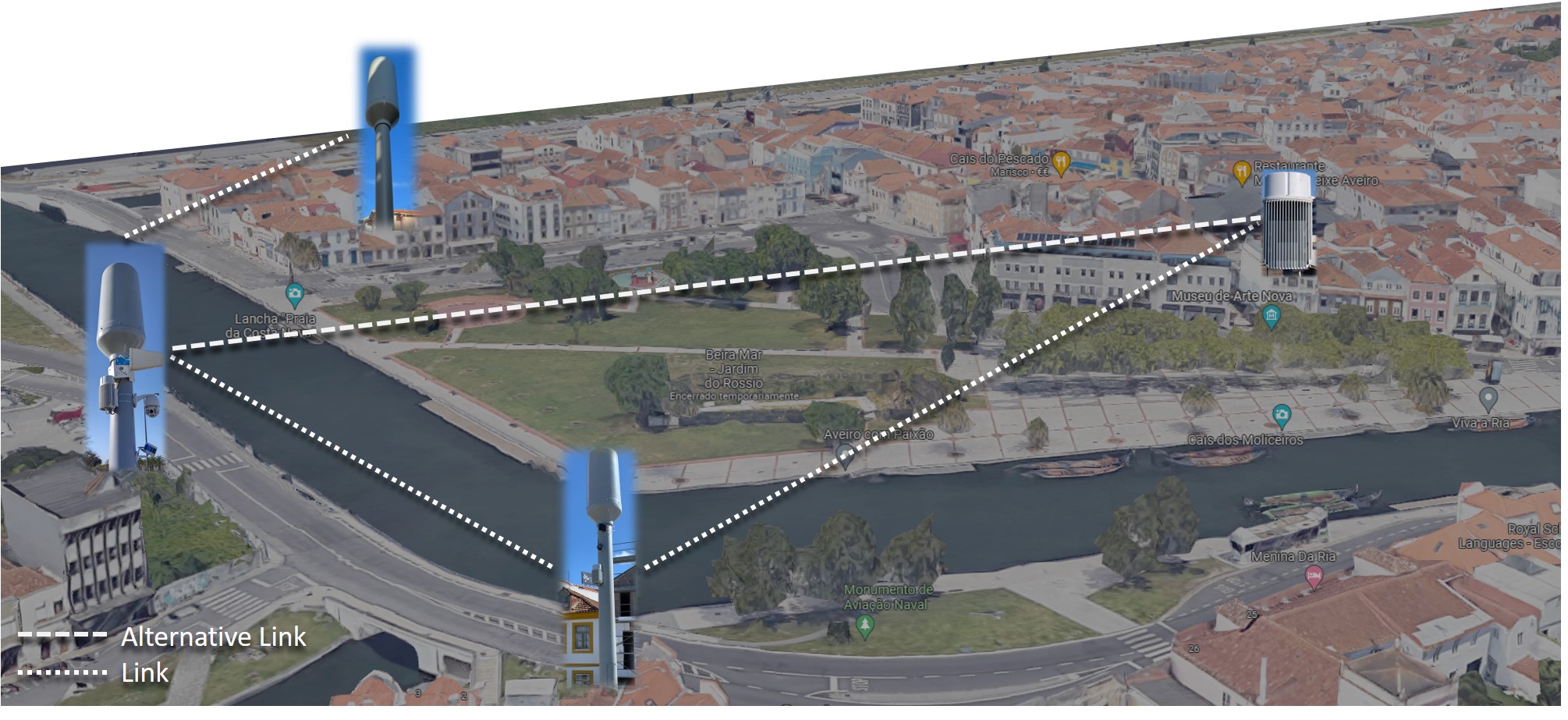
The contributions of this paper are as follows: We look into the unique dynamic behaviour of mmWave communication environment, and propose how to use SW-RLNC, both F-SW-RLNC and A-SW-RLNC versions of [19, 20], to capture rapid changes and mitigate the high losses that are intrinsic to mmWave, for LLC and URLLC. In particular, we study the interplay of cross-layer solutions, and propose how one can mitigate the large delay caused by the lower-layer error control mechanisms. We further, theoretically, study the SW-RLNC scheme in terms of its maximum delay guarantees over the transport-layer mmWave channel model. This worst-case analysis plays an important role in URLLC compared to the customary average analyses that are performed in the recent literature. We evaluate the performance of our solution over our mmWave testbed deployed in the city of Aveiro (Fig. 1). For our study, we have collected a representative dataset in the mmWave backhaul network, and the obtained results show that A-SW-RLNC scheme can obtain URLLC, with a maximum delay below 10 ms with more than 99% success rate.
The remaining of this paper is organized as follows: Section II describes the mmWave technology - PHY and MAC layer mechanisms -, the system model and problem formulation. Section III presents different RLNC approaches, and in specific, the A-SW-RLNC. Section IV presents the experimental network test scenario, the methodology, and the experimental results by comparing various RLNC approaches in terms of their key performance metrics, i.e., throughput, mean in-order delay, and maximum in-order delay. Section V is dedicated to the theoretical validations of the results: mathematical modeling of the transport-layer mmWave channel and bounding the in-order delivery delay. Finally, Section VI summarizes the findings and discusses future research directions.
II Problem Statement and Preliminaries
This section provides a technical background of mmWave technology, the system model and the problem formulation.
II-A MmWave Communications and Challenges
The wireless propagation channel can vary significantly over time, greatly affecting the radio’s link quality. This is especially significant for technologies that operate in the mmWave band, such as IEEE 802.11ad [23], as the higher frequencies cause higher susceptibility to the blockage.
To mitigate the negative impact of obstructions, Wigig-based COTS devices, such as the CCS Metnet nodes [24], employ an automatic mode to dynamically select the parameters of modulation and error correction based on the instantaneous Signal-to-Noise Ratio (SNR) and error rate [25]. Specifically, devices can switch between four modes of operation, each having specific modulation and Forward Error Correction (FEC) schemes, and all utilize the 60 GHz carriers: a) control PHY (Modulation and Coding Scheme - MCS 0); b) Single carrier (MCS 1-12) PHY; c) OFDM (MCS 13-24) PHY; and d) low-power SC (MCS 25-31) PHY. This set of choices makes it possible to meet different performance requirements, depending on the usage scenario (e.g., low-interference, low-complexity, low-energy-consumption, etc.).
The 802.11ad PHY standard utilizes Low-Density Parity-Check (LDPC) codes with four different rates (1/2, 5/8, 3/4, and 13/16), with a fixed codeword length of 672 bits [26]. Each modulation type combined with a specific code rate form a MCS. More details regarding the modulation schemes, code rates and data rates that are supported by each MCS are specified in Table I. For the rate identification, the manufacturers can adopt a maximum frame size of 2000 bytes, and the calculations are performed in the second layer.
|
MOD | Code rate |
|
|
|
||||||||
|---|---|---|---|---|---|---|---|---|---|---|---|---|---|
| 0 | DSSS | 12 | -84.52 | -11 | 22.4 | ||||||||
| 1 | BPSK | 1/2 | -73.72 | -0.2 | 308 | ||||||||
| 2 | BPSK | 1/2 | -72.52 | 1 | 616 | ||||||||
| 3 | BPSK | 5/8 | -71.32 | 2.2 | 770.4 | ||||||||
| 4 | BPSK | 3/4 | -69.92 | 3.6 | 924 | ||||||||
| 5 | BPSK | 13/16 | -69.02 | 4.5 | 1000.8 | ||||||||
| 6 | QPSK | 1/2 | -69.72 | 3.8 | 1232 | ||||||||
| 7 | QPSK | 5/8 | -68.22 | 5.3 | 1540 | ||||||||
| 8 | QPSK | 3/4 | -66.72 | 6.8 | 1848 | ||||||||
| 9 | QPSK | 13/16 | -65.72 | 7.9 | 2002.4 |
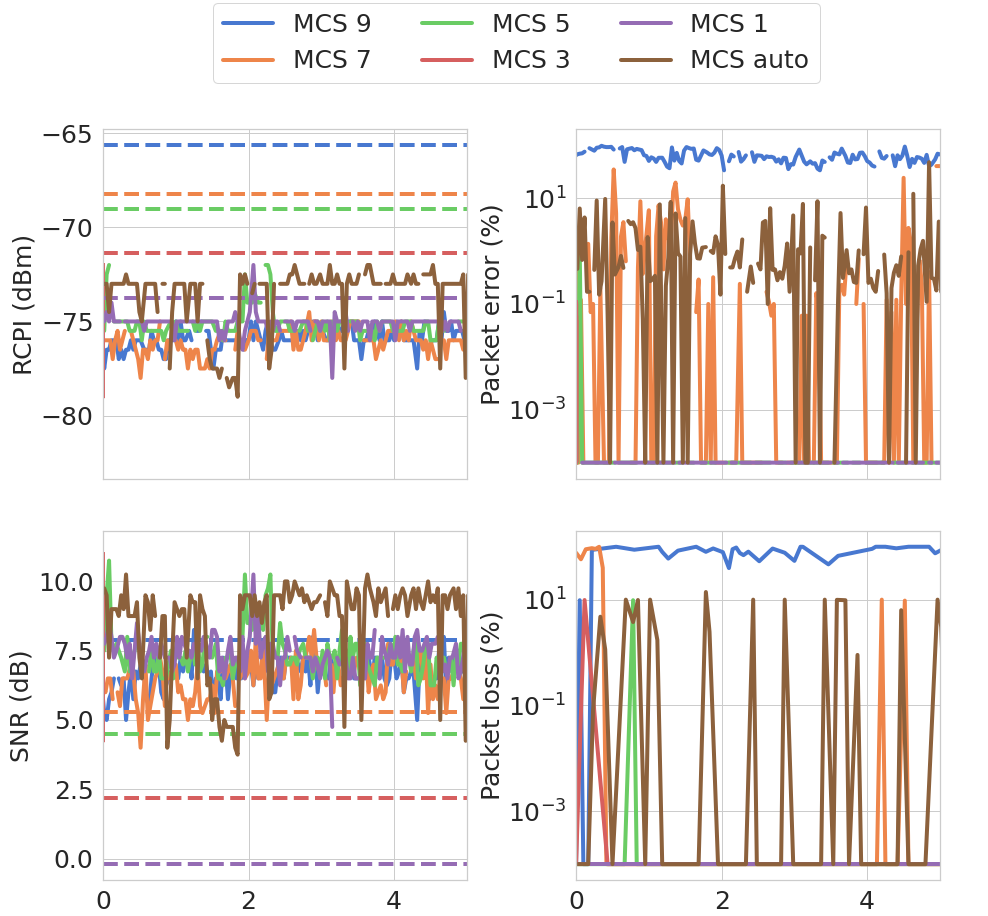
Fig. 2 presents a set of measurements performed in a mmWave outdoor setup, further described in Section IV-A, considering an obstructed scenario. Several PHY layer metrics were recorded, such as, Received Channel Power Indicator (RCPI), SNR, and Packet Error Rate (PER), and one transport layer metric, packet loss rate, for different MCS modes (fixed and automatic). In addition, the figure also shows the minimum required levels of SNR and RCPI reported by the manufacturer for maintaining each MCS (the dashed horizontal lines). As shown, under obstruction, the RCPI signal level drops to a lower value than the defined threshold for almost all fixed MCSs (with the exception of MCS 1). However, the SNR requirement is still being fulfilled most of the time. Note that sudden decreases of the RCPI and SNR occurred due to slight obstacle movements. Moreover, the figures show that using higher modulation modes in an obstructed scenario may lead to packet error rates up to 90% in the PHY layer, and packet loss rate up to 100% in the transport layer. On the other hand, automatic modulation adjustment leads to lower packet losses and packet error rates, under a static obstruction.
Still, switching MCS to a more robust scheme (i.e., with a lower code rate) whenever the signal quality drops may not be enough to ensure a reliable connection. This is because a sudden obstruction of the LOS path can cause a significant decrease in the maximum achievable throughput, increasing the delay. This leads to several issues in the upper layers, such as link quality judgment, rate adaptation, and bufferbloat [6, 7]. Link fluctuations will affect TCP performance when mmWave links switch between LOS and non-LOS links states, resulting in TCP retransmissions, an increase of the Round Trip Time (RTT), and consequently, a decrease of the congestion window. The variability of the links also prevent some protocols to achieve the ultra-high bandwidth capacity of the mmWave links. The Bandwidth-Delay Product (BDP) used to compute the optimal buffer size is difficult to estimate, resulting in high latency and jitter when using larger buffers to prevent packet losses.
Thus, algorithms that are faster to adapt to the conditions of the link have major advantages for this setting (e.g., A-SW-RLNC), which is the main scope of the current paper. We use an effective network coding solution that can be introduced in the transport layer to mitigate the losses and handle the high variations of delay caused by obstructions. This, in turn, lightens the requirements of the FEC mechanisms implemented at the PHY layer. This is especially useful in mmWave networks where blockage increases the delay, packet losses, and the number of TCP retransmissions.
II-B System Model and Problem Formulation
We consider a real-time slotted mmWave communication with feedback. In particular, a Single-Path (SP) communication setting is considered between two points, sender and receiver, and we assume that the data that needs to be transmitted consists of packets of the same size, i.e., . At the -th time step, the sender transmits a coded packet over the noisy mmWave forward channel. The receiver may acknowledge the sender by sending an Acknowledgment (ACK) for any delivered coded packet over the noisy feedback channel. The delay between the first time data is transmitted and the time that the corresponding feedback is received is called RTT. The transmission delay of coded packets is the time it takes for the sender to transmit one packet (push the packet into the medium), and the propagation delay is the amount of time it takes for one packet to be received from the sender to the receiver and vice versa. We assume that the size of the feedback acknowledgment is negligible, and that the propagation delay can vary for any transmitted coded packet according to the channel’s condition. Hence, the RTT for each coded packet is equal to , where . Let the timeout to denote an adaptive parameter the sender may choose to declare the packets that were not delivered at the receiver. That is, for any coded packet transmitted, if an ACK is not received at the sender after time slots, the sender declares a Negative Acknowledgment (NACK) for the corresponding packet.
Our main performance metrics are defined as follows:
(1) Throughput . This is defined as the rate, in units of bits per time slot, at which the information is delivered at the receiver. In this paper, we focus on a normalized throughput, denoted by , which corresponds to the total number of information bits delivered to the receiver divided by the total amount of bits transmitted by the sender.
(2) In-order delivery delay of packets . This is the difference between the time slot in which an information packet is first transmitted at the sender and the time slot in which the packet is decoded, in order, by the receiver.
Our goal in this setting is to maximize the throughput, while minimizing the in-order delivery delay of packets.
III Network Coding for Joint Scheduling and Coding
This section elaborates on using RLNC as an error correction mechanism in the transport layer between two points. This mechanism mitigates the rigid requirements of the physical layer error correction code to provide reliable communications for the worst mmWave channel condition. Thus, one can increase the performance in terms of throughput and delay as defined in Section II-B.
In classical RLNC schemes [16, 17], each encoded packet , where is a positive integer, that is transmitted over the lossy communication is a random linear combination of the original uncoded packets, i.e.,
| (1) |
where the coefficients are drawn from a sufficiently large field, and is the total number of original uncoded packets. In general, when the coefficients are randomly sampled from a large field, the receiver can decode the original packets once coded packets are received, for example using the Gaussian elimination technique.
Although classical RLNC schemes can achieve the desired communication rates in the realm of large , it imposes a large latency to the system. This is because, to decode the first packet, at least coded packets need to be transmitted. Thus, some variations of RLNC have been studied in the literature to lower the latency [9, 8, 12, 13, 11, 19]. In our proposed scheme, we compare part of these methods, which will be next described, over several mmWave settings in Section IV.
III-A Rateless RLNC (R-RLNC)
In this variation, the sender’s packets are split into non-overlapping blocks, called batches, each with size of packets. The batches are encoded and transmitted in order. For each batch, the encoded packets are random linear combinations of the packets within the same batch, and the ratio of the number of original packers and the number of encoded packets denotes the rate of the scheme. In a well-designed scheme, the receiver is able to recover the whole batch per receipt of its out of encoded packets. More precisely, let be the -th encoded packet of the -th batch, where , then
| (2) |
Here, it is assumed that the total number of packets is divisible by the block size. If not, one can easily use the zero-padding techniques. In this variation, the code designer in advance can try to manage the performance, in terms of throughput and latency trade-off, by choosing the size of and .
When the sender does not receive an acknowledgement, by the end of transmitting the -th coded packet, of a batch of at least packets, it starts sending another coded packets (with different coefficients) for the same batch. This process continues until the sender ensures that coded packets are received at the destination. Therefore, this RLNC scheme is by-definition a rateless code [27], and we call this scheme R-RLNC.
Recently, there are new solutions in the literature where the size of the -th uncoded batch and the size of the -th coded batch can be time-variant and adapted based on the channel estimation [18, 28]. However, those solutions are only adaptive and reactive to the average packet loss probability. In mmWave communications, the channel conditions vary extremely fast; hence, although the above solutions are adaptive, one can pay in performance as those solutions do not track the specific erasure pattern of each packet and batch.
III-B Adaptive and Causal RLNC
This is an adaptive and causal variant (A-SW-RLNC method), as given in [19]. In this method, at a time slot, according to the cumulative feedback information, the sender can decide either to transmit a new coded linear combination, i.e., new packet, or repeat the last sent combination, same packet. Here, same and new refer to the raw information packets contained in the linear combination, such that sending the same linear combination means that the raw information packets are the same but with different random coefficients. Thus, using a sliding window mechanism, the -th coded packet can be described as follows,
| (3) |
where corresponds to the oldest raw information packet that is not yet decoded, and is incremented each time a new raw information packet is decided to be included in the linear combination by the sender.
The A-SW-RLNC solution tracks the channel conditions, and adaptively adjusts the retransmission rates based on the channel quality and the feedback acknowledgments. For the channel estimation, the behavior of the channel parameters (i.e. erasure probability and its variance) is tracked using the feedback acknowledgements over time. A-SW-RLNC envisions two different FEC mechanisms to add redundancy (retransmissions) and cope with the errors and failures, according to the channel status. The first one is and the second one is , and they both interplay to obtain a desired throughput-delay trade-off. The first FEC mechanism is , as it sends redundant packets in advance (before the failure occurs) according to the average estimation of the channel behavior. The second FEC mechanism is , as it sends redundant packets according to the realization of errors, identified using the feedback information. It is through the second mechanism that the sender ensures that decoding is eventually possible at the receiver. We note that, the higher the number of FECs is, the lower is the delay and the throughput, as it pro-actively recovers (possibly more than needed) for future lost coded packets. On the other hand, the higher the number of FECs is, the higher is the delay and the throughput, as it only recovers for the needed lost coded packets at the cost of a delay proportional to RTT. The way to adjust this trade-off is through an adaptive approach, which is described in detail in [19].
IV Experimental Study and Performance Evaluation
This section presents the experimental study of several transport layer communication solutions over mmWave links. We start by presenting the setup, characterizing the mmWave communication in terms of the packet loss and RTT, and then we discuss the performance of several communication solutions with respect to the LLC and URLLC requirements.
IV-A Experimental Outdoor mmWave Setup
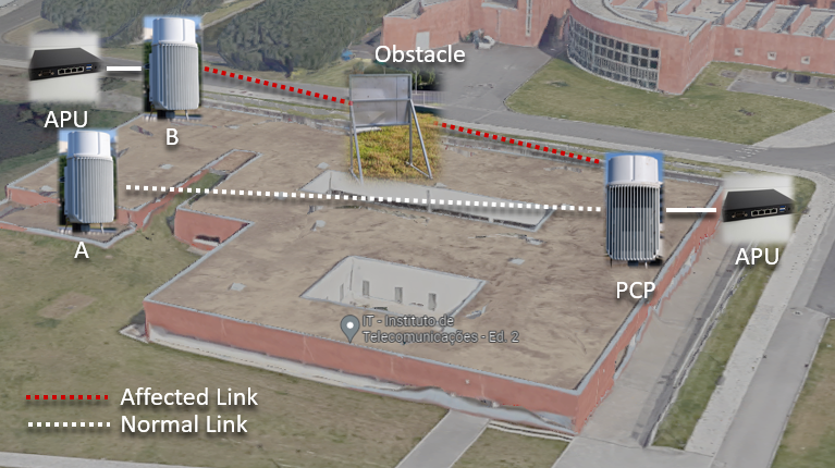
The mmWave network is composed of three CCS Metnet nodes [24], which are presented in Fig. 3. These nodes were deployed in an outdoor environment, specifically on the rooftop of Instituto de Telecomunicações, in Aveiro (Portugal), which allowed running tests under a fully controlled environment. The deployed network adopts an architecture where the Personal basic service set Control Point (PCP) node has a wired connection to the core network. On the other hand, nodes A and B, the remote nodes, access the network through the radio links they establish with the node PCP. For each node, there is a single board unit (APU) connected, that will communicate using the mmWave backhaul.
Furthermore, these nodes employ the standardized IEEE 802.11ad (WiGig) technology, which operates between the 57 GHz to 66 GHz unlicensed frequencies, to form a wireless 5G meshed backhaul capable of accommodating hundreds of gigabit traffic from the core network. Each device has four radio modules, each employing a 19 dBi beamforming steerable antenna that establishes directional links to cope with the increased attenuation at 60 GHz. For that purpose, the Wigig standard has proposed MAC and PHY layer enhancements which include support for directional communication through a process known as beamforming training, which allows determining the appropriate transmit and receive antenna sectors for communication between a given pair of stations. By employing beamforming techniques, the 300º horizontal field covered by each device is divided into 64 discrete sectors (with a 5º horizontal beamwidth) that can be used to concentrate the signal towards a specific direction.
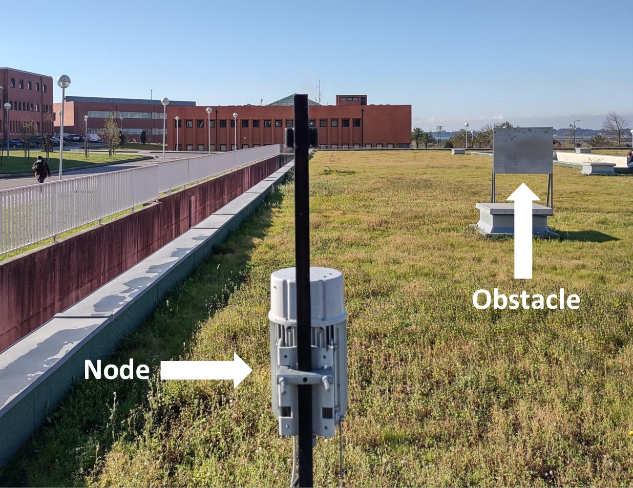
In the experimental scenario, a metallic obstacle was placed between two Stations (STAs) to simulate the blockage scenario represented in Fig. 4. This obstacle was maintained in a fixed location for the entire test duration (25 minutes, i.e., 5 minutes per MCS mode). After the introduction of the obstruction, a significant reduction of the instantaneous Received Signal Strength Indicator (RSSI) and SNR was observed compared to the average values registered under non-obstructed operation (see Fig. 2).
IV-B Data Collection: Recording the mmWave Channel Profile
The dataset characterizing the mmWave channel behavior, i.e., the RTT and the packet loss event at each time slot, was collected using the mmWave setup illustrated in Fig. 3 and Fig. 4. UDP traffic was generated, and at the same time, the RTT and the state of the packet (being erased or not) were collected using the Two-Way Active Measurement Protocol (TWAMP) tool. The tool implements the standard defined in the RFC 5357[29], which is capable of performing two-way or round-trip measurements. Under the presented scenario, one of the Linux APU nodes was selected to be the sender, while the other was acting as a reflector. The TWAMP tool was executed as a server on the reflector APU, up until the end of the dataset creation.
The unprocessed dataset consists of a 5-minute execution of the TWAMP tool for each MCS mode (i.e., MCS 3-MCS 6, and MCS Auto). The time slot duration is 450 s, which is obtained by trial and error as the maximum value without losing packets due to processing limitations. To minimize the measurement error, given that TWAMP one-way directional delays are clock sensitive, the system clocks on the APUs were synchronized using the Network Time Protocol (NTP), forced after each periodic measurement process. In order to evaluate the channel behaviour and collect the metrics needed by the adaptive communication solutions, we retrieved from the unprocessed dataset a sequence of tuples, represented as (RTT, packet loss) per time slot. We call this sequence a Channel Profile (CP), which will be used in our proposed emulator described in the next subsection. In total, we obtained one channel profile for each MCS mode in .
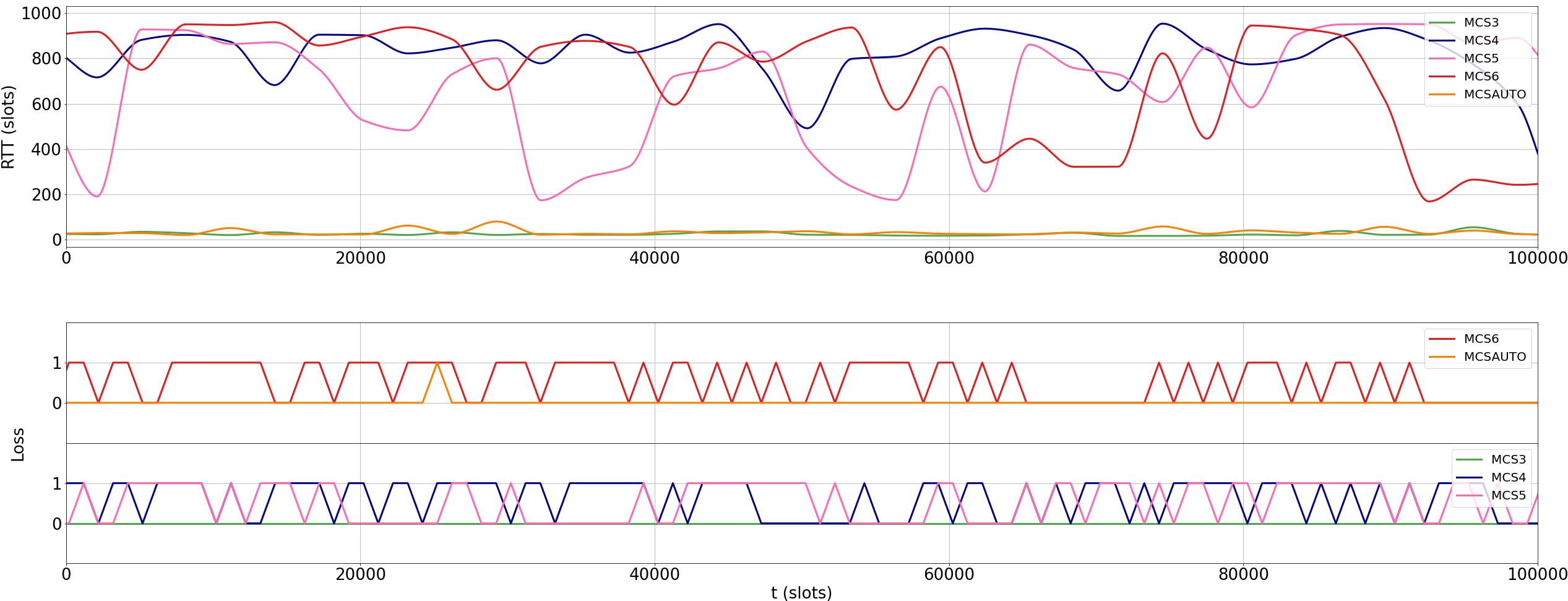
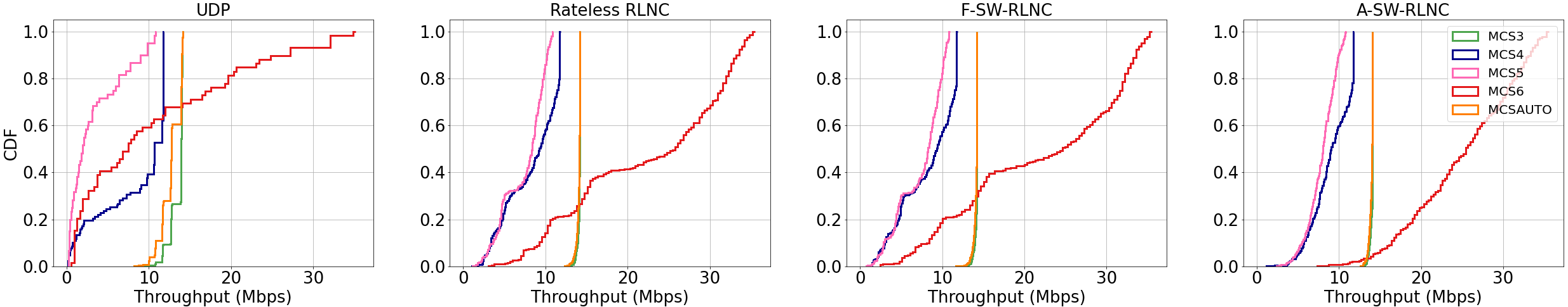
Fig. 5 presents the RTT and packet loss event, i.e., the CP, for several MCS modes obtained in the outdoor mmWave testbed. As expected, packet loss is more prominent for higher MCS values, due to the use of the combination of less reliable modulation (QPSK/BPSK) with a higher FEC rate. Another interesting finding is the presence of bursty errors (more theoretical insights and validations will be presented in Section V-A). Furthermore, the collected data shows that, locking MCS 3 for both directions and setting the antenna modules to select the MCS mode according to the channel state (MCS Auto) yields similar behaviors when partially obstructed by the metallic plate. Moreover, a high RTT variance for MCS 4 through MCS 6 was observed, leading to several issues in the upper layers. This RTT fluctuation affects the efficiency of RLNC-based schemes, due to their late reaction to successfully-decoded packets.
IV-C Emulation: Communication over Transport-Layer mmWave Channel
To evaluate the performance of the transport-layer communication solutions under the collected channel profiles CPs, an emulator was developed on top of Steinwurf’s Kodo FEC components [30] (using research license). Our implementation of the Rateless RLNC (sec. III-A), the Sliding Window variant of the Rateless (F-SW-RLNC), and the A-SW-RLNC (sec. III-B) are built upon the Block and Slide RLNC schemes in these libraries, which we extended accordingly.
The baseline scenario is represented as a UDP transmission of a pseudo-randomized binary file, emulated using the recorded CP (see Fig. 5). The scenario consists of a file divided into 100 datagrams of 1000 bytes each. Each successful delivery under the defined scenario using a communication algorithm is called an experience. The completion of an experience outputs a triple, consisting of the normalized throughput, the mean and the maximum in-order delay metrics. A datapoint is then defined as the mean of each metric over 10 experiences. The simulation will complete when all time slots from a CP are used (i.e., the length of the CP sequence is exhausted). The total set of datapoints is then collected per tested CP and communication solution.
IV-D Performance Analysis of RLNC Solution over mmWave
After running the emulator with the collected channel profiles, we were able to obtain the main performance metrics for several transport-layer communication solutions. Our results show a significant improvement regarding the in-order delivery delay and normalized data throughput, when network coding is used to improve the communication in the transport layer. Next, we evaluate these performance metrics in detail.
IV-D1 Throughput
| Throughput (Mbps) | Mean In-Order Delay (slots) | Max In-Order Delay (slots) | ||||||||
|---|---|---|---|---|---|---|---|---|---|---|
| Mode | Algorithm | Mean | Stdev | Mean | Stdev | Mean | Stdev | |||
| MCS3 | UDP transmission | 13.57 | 0.86 | 14.17 | 6.29 | 7.74 | 32.95 | 8.95 | 7.74 | 35.67 |
| Rateless RLNC | 14.08 | 0.35 | 14.22 | 37.67 | 2.64 | 51.62 | 42.52 | 2.84 | 40.80 | |
| F-SW-RLNC | 14.15 | 0.18 | 14.22 | 3.85 | 1.97 | 12.11 | 8.13 | 4.24 | 24.21 | |
| A-SW-RLNC | 14.00 | 0.19 | 14.08 | 3.11 | 0.29 | 4.31 | 3.86 | 1.95 | 11.38 | |
| MCS4 | UDP transmission | 8.62 | 4.27 | 0.23 | 425.44 | 1180.34 | 5106.57 | 427.41 | 1180.38 | 5108.70 |
| Rateless RLNC | 8.10 | 3.59 | 1.40 | 140.53 | 180.12 | 765.62 | 148.18 | 181.56 | 779.55 | |
| F-SW-RLNC | 8.33 | 3.39 | 1.59 | 114.29 | 163.71 | 681.71 | 145.74 | 175.30 | 734.11 | |
| A-SW-RLNC | 9.11 | 2.36 | 3.87 | 16.66 | 20.04 | 80.23 | 63.86 | 77.37 | 324.84 | |
| MCS5 | UDP transmission | 3.37 | 3.32 | 0.22 | 1004.99 | 1300.52 | 4980.49 | 1007.07 | 1300.57 | 4982.72 |
| Rateless RLNC | 7.07 | 2.87 | 1.23 | 137.53 | 178.17 | 805.66 | 146.27 | 179.22 | 820.97 | |
| F-SW-RLNC | 7.40 | 2.74 | 1.57 | 115.35 | 149.07 | 635.49 | 156.07 | 154.91 | 688.98 | |
| A-SW-RLNC | 7.93 | 1.72 | 3.68 | 17.72 | 19.50 | 98.44 | 68.36 | 73.52 | 328.87 | |
| MCS6 | UDP transmission | 10.64 | 9.78 | 0.80 | 1029.80 | 1299.62 | 4601.51 | 1031.76 | 1299.59 | 4604.08 |
| Rateless RLNC | 21.39 | 10.36 | 3.45 | 177.93 | 228.41 | 999.80 | 186.20 | 229.38 | 1009.81 | |
| F-SW-RLNC | 22.04 | 10.07 | 3.97 | 154.31 | 192.85 | 848.23 | 193.42 | 199.65 | 899.50 | |
| A-SW-RLNC | 25.17 | 6.36 | 11.01 | 22.28 | 23.63 | 100.38 | 87.16 | 88.85 | 405.18 | |
| Auto | UDP transmission | 12.82 | 1.21 | 14.15 | 12.96 | 11.63 | 43.20 | 15.60 | 11.63 | 45.82 |
| Rateless RLNC | 13.98 | 0.50 | 14.22 | 38.31 | 4.03 | 55.08 | 43.27 | 4.20 | 61.43 | |
| F-SW-RLNC | 14.08 | 0.27 | 14.22 | 5.15 | 3.29 | 15.43 | 11.25 | 6.48 | 29.90 | |
| A-SW-RLNC | 13.92 | 0.24 | 14.08 | 3.22 | 0.42 | 4.90 | 4.78 | 2.71 | 14.85 | |
The results in Fig. 6 show that the robustness of the A-SW-RLNC over the mmWave network link pertains a higher overall throughput compared to the UDP baseline across all MCS modes, despite the high RTT variance. Besides, higher MCS modes obtain higher throughput gains as expected. For MCS 3 and MCS Auto, A-SW-RLNC tops other coding solutions only slightly ahead, and at the same time presents a consistent behaviour (i.e., less fluctuations). Table II shows that, for the MCS Auto mode, there is no notable difference on the 99th percentile between the Rateless-RLNC and the A-SW-RLNC. This means that A-SW-RLNC shows no significant throughput penalty while, as we show later, it results in significant delay improvements.
IV-D2 Mean In-Order Delivery Delay
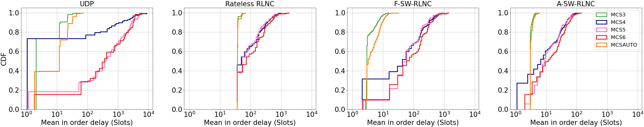
Our results show that the A-SW-RLNC solution performs exceptionally well regarding in-order delivery delays in comparison with the simpler rateless solutions over the mmWave channel profiles, as illustrated in Fig. 7. Regarding the mean in-order delay, with MCS 3 and MCS Auto modes, CDF curves show that the simple UDP transmission achieves lower delays than the R-RLNC scheme. In R-RLNC, a batch of packets is decodable only if the decoder receives a number of coded packets equal to the number of original packets in the batch (Section III-A). The sender, thus, keeps sending batches of encoded data for the same generation until it ensures the batch can be decoded, and this limits the minimum theoretical achievable delay. The F-SW-RLNC implementation removes this limitation and achieves better results for the upper quartile and above with an order of two, see Fig 7.
For high MCS modes, the sharp increase in the channel erasure rate makes a simple UDP file transfer to be unusable, as file retransmission probability is substantial, therefore increasing the packet in-order delivery delay. The R-RLNC implementation mitigates these losses via a generous code redundancy, improving the in-order delay of a UDP transmission. From the CDF curves, gains start for the upper steps of the 20th percentile. For the MCS 6, regarding the 99th percentile of the mean in-order delay, the R-RLNC outperforms the UDP transmission by a factor of 4.60 (i.e., 4601.5/999.80). Further, for the MCS 6, the A-SW-RLNC outperforms the R-RLNC with a factor of 9.96 (i.e., 999.80/100.38) in the 99th percentile of the mean in-order delay, see Table II. This order of magnitude improvement over R-RLNC is attained thanks to the the adaptive and dynamic component of A-SW-RLNC (Section III-B).
IV-D3 Maximum In-Order Delivery Delay
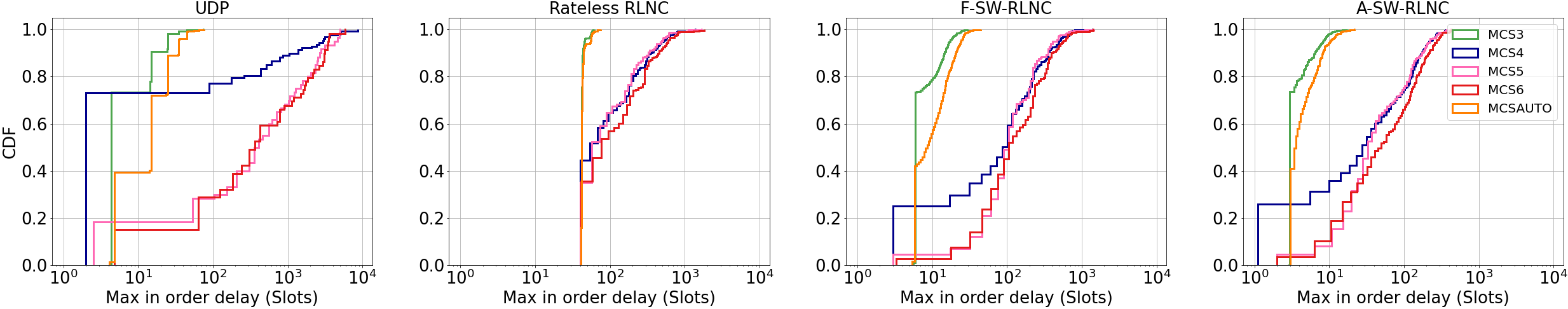
With respect to the maximum in-order delivery delay, it is shown in Fig. 7 that the R-RLNC algorithm does not differ much from the previous average delay analysis, showing that its bounds are quite close. For the MCS 6 and in the 99th percentile, the statistical values for the maximum delay show a significant improvement with a factor of 4.22 (i.e., 4604.08/1009.81) times for R-RLNC compared to UDP transmission and 11.36 (i.e., 4604.08/405.18) times for A-SW-RLNC compared to UDP transmission, respectively. Similar to the average analysis, the F-SW-RLNC shows a slight improvement in the maximum in-order delivery delay. A-SW-RLNC achieves an improvement with a ratio of 2 to 2.5 across all percentile bounds over the former approach (F-SW-RLNC), from MCS Auto to MCS 6.
IV-D4 LLC and URLLC Performance Indicators
Regarding the support of low latency and ultra-reliable scenarios in the mmWave IAB, Table II highlights the schemes that are capable to achieve LLC and URLLC requirements. For LLC applications, we target a mean in-order delay below 10 ms (22 slots). For URLLC applications (only ), a max in-order delay below 10 ms (22 slots) is targeted. As presented in Table II, only the A-SW-RLNC can support URLLC applications, at MCS 3 and MCS Auto modes, by obtaining a max in-order delay below 10 ms for . In such lossy links, transport protocols like UDP cannot be used in URLLC scenarios, as well as the rateless and the F-SW-RLNC schemes. When addressing LLC applications, the A-SW-RLNC scheme is capable to achieve a delay below 10 ms in all the MCSs evaluated, allowing the increase of the network bandwidth by using a higher MCS. As presented, low-layer techniques are very conservative and do not allow to take the full benefits of the mmWave link capacity.
V Theoretical Validations
In this section, we perform theoretical validations for the field experiments of Section IV. In the first subsection, we investigate the packet loss sequence for the transport-layer mmWave channel, and demonstrate that it can be well-modeled with a Gilbert-Elliott (GE) channel with erasures [31, 32]. Obtaining the mathematical model for the channel enabled us to derive upper-bounds on the in-order delivery delay of our communication solution, in the second subsection, which is very helpful to define delay guarantees.
V-A Modeling the Transport mmWave Channel
Here, we take a closer look at the nature of errors observed in the testbed experiments in Section IV. The point-to-point packet loss pattern observed in the transport layer mmWave channel has a bursty behaviour, resulting in a contiguous sequence of packets to be erased in the case of failure. The top panel of Fig. 8 shows a binary sequence that indicates whether or not a packet is lost at a time slot, for the MCS 5, according to the field data. The same bursty behaviour was observed across all the MCS modes. Such behavior was already shown in [7] and can be explained by the LOS characteristics of the mmWave. When the link is blocked, the connection between the two stations is lost, and the Sector Level Sweep (SLS) mechanism searches for a new pair of sectors capable to restore the link. The search time depends not only on the interference nature, but also on the size of the array of antennas, which could exceed the timeout.
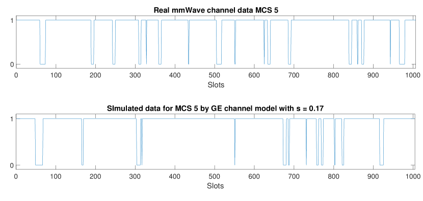
Therefore, we model the point-to-point mmWave channel, observed from the transport layer, as a Gilbert-Elliott (GE) channel with erasures. The channel model is a Markov process with two states, i.e., good and bad. In the good state, the erasure probability is zero, and in the bad state, the erasure probability is one. We denote with and , the transition probabilities from good state to bad state, and from the bad state to good state, respectively. The stationary distribution of the GE channel is given by and . The average erasure rate is , and is the average erasure burst. By computing the average erasure rate and the average erasure burst, from the data we collected in our experiments for MCS 5, we set and . Hence, the transition probability from the bad state to good state is given by . The bottom panel of Fig. 8 illustrates the packet loss sequence, for the MCS 5 mode, according to the GE channel model.
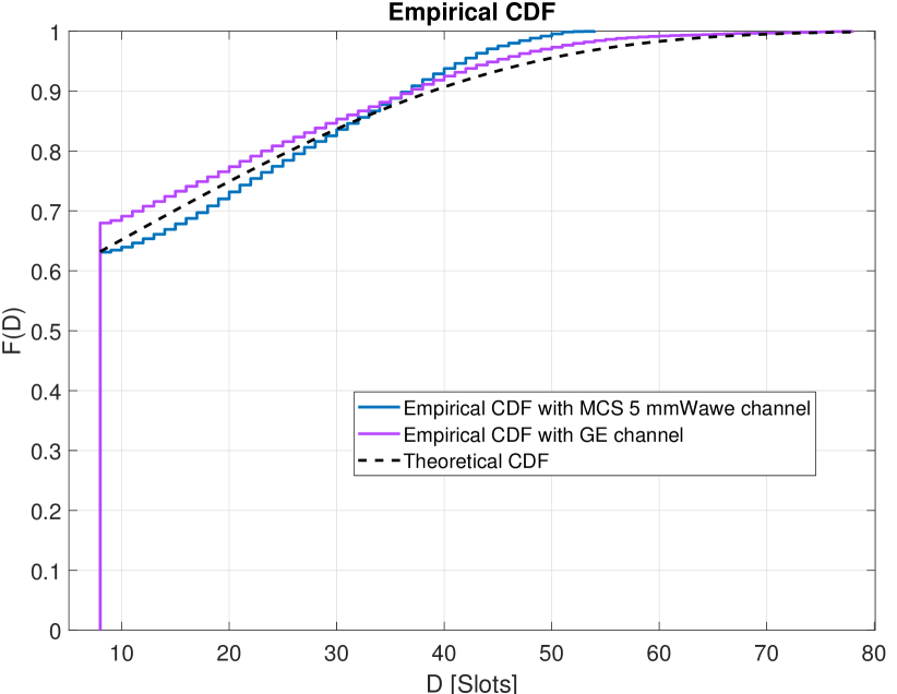
We then use the A-SW-RLNC solution [19] simulated over GE channel with the aforementioned parameters and . Fig. 9 shows the empirical CDF of the in-order delivery delay for the two sets of data. As we observe, there is a good agreement between the empirical distribution of delays, based on the simulator and the real-field mmWave data, which validates that the GE channel is the appropriate model to approximate the bursty mmWave channel we observed from the transport layer. The theoretical curve with dashed line shows the CDF for the type 1 extreme value distribution with location and scale parameters equivalent to the empirical mean and standard deviation of delays. It is used to model the distribution of the maximum of a number of samples.
V-B Delay Analysis of A-SW-RLNC Solution with Cross-Layer Considerations
In this subsection, we investigate the statistical properties of the in-order delay for the transport-layer A-SW-RLNC solution over the GE channel model, to provide theoretical delay guarantees. Here, we follow similar techniques as used in [19, 33], with the difference that instead of considering the average failure rate, we consider an extreme value, such that most of the time the erasure rate falls below this value. Such extreme analysis is necessary to provide delay guarantees required by the URLLC.
The transport-layer estimation of the average erasure probability at the -th time slot, as represented by the feedback acknowledgements from the MAC layer [7, 34, 35, 36], is given by
Here, is the binary feedback acknowledgement at the time slot . We note that, for tracking the channel rate, only the number of positive ACKs matters, and their association with particular packet indices (being in-order or not) is not needed.
The erasure rate is time-variant for the GE channel, which affects the bounds we can define on the in-order delivery delay. Practically, using its average value and the standard deviation, we can obtain an upper-bound on the erasure rate, such that, most of the time the erasure probability falls below this bound, i.e.,
| (4) |
where is the variance of the channel during one RTT period, and is the confidence factor, using the deviation rule. Therefore, we use this conservative measure of the erasure probability to obtain an upper bound on the delay with some strong guarantees to hold.
As elaborated in Section V-A, the behavior of the bursty transport layer channel can be represented by using a GE channel model with erasures. For (erasure probability in the good state) and (erasure probability in the bad state) the average erasure rate is given by , and the variance by
We note that the delay guarantees provided can be considered for other channel models using their mean and variance statistics, in a similar fashion.
By incorporating the extreme-case erasure rate in the retransmission condition of the A-SW-RLNC solution, we obtain
| (5) |
Here, is the rate of degrees of freedom (Dofs), i.e., the ratio of the number of DoFs needed to decode the transmitted coded packets (see (3)) and the number of DoFs added by apriori and aposteriori FECs, and is a threshold influencing the throughput-delay trade-off. The retransmission criteria appears in probabilistic expressions, e.g., retransmission probability, that determine an upper bound on the mean in-order delay in [19, Section V.A]. Thus, by considering the extreme-case erasure rate , we obtain bounds on these probabilities.
For the upper bound on the in-order delivery delay in [19], it also appears a scaling term which indicates the maximum number of retransmissions needed to succeed in the forward channel. For the GE channel model, this upper bound on the scaling factor is given by
| (6) |
Using the two considerations (5) and (6), and the similar techniques as in [19], we derive upper-bound on the in-order delivery delay, that holds with a high probability (rather than the mean in-order delay). This probability is tune-able using the confidence parameter in (4).
Next, we evaluate the derived bounding methodology on our collected field data and simulated data. Fig. 10 shows the upper bound on the in-order delivery delay for several values of as a function of the average erasure rate and for , given , . As we observe, the probabilistic upper bound increases, by increasing , however, with a higher probability to be satisfied.

The theoretical analysis performed in this section helped us define bounds on the delay, such that the observed delays fall below these bounds with a high probability. This probability, which we call probability of success , depends on the , the confidence factor we considered when we deviated from the average value of erasure rate in our analysis. By increasing , the upper-bound also increases, but it holds with a higher probability. In fact, each value of corresponds to an upper-bound of the in-order delivery delay (horizontal axis of Fig 9), and is the value of the CDF function at this delay (vertical axis of Fig 9). As presented in Fig 10, the theoretical results show that the in-order delay for (), with an is around 73 slots. This value is close to the empirical results of Section IV-D, where the MCS 5 mode achieves 98.44 slots for the mean in-order delay.
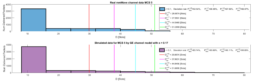
Fig. 11 shows the empirical distribution for the in-order delivery delay of the simulated and field data. The derived upper-bound on the delay for several values of are indicated as vertical lines. The ratio of the points where the in-order delivery delay falls below these vertical lines, i.e., , appear in the legend. We highlight that changing the view from the average analysis of delay to the worst-case scenario is particularly important for URLLC applications, where guarantees are demanded on the in-order delivery delay.
VI Conclusions and Future Visions
In this work, we proposed a significant enhancement on the mmWave performance by incorporating network coding algorithms to stabilize the high-frequency communication sensitivity. In particular, we showed that, using A-SW-RLNC, it is possible to obtain ultra-reliable high bandwidth while reducing by up to an order of two the mean in-order delay. Our results demonstrate that the communication protocols can notably take benefit from relaxing the PHY and MAC layer error control mechanisms, and delegating the task to the upper layers using the proposed network coding solution. In fact, the retransmissions that occur due to MAC error control mechanisms are effectively not needed once the network coding solution and FEC mechanisms are utilized.
As for future work, we plan to use the gain of Multi-Path (MP) network coding communication through splitting the mmWave band into several sub-bands. For this end, we will extend the proposed SP solution to several frequency links via an effective MP coded communication [20]. To use the proposed solution over highly-meshed backhaul of novel communication networks, we plan to incorporate software-defined controllers for collecting information that can enhance the communication performance over meshed mmWave communication [37]. Last but not the least, we plan to exploit the recent trend in the estimation of error patterns using deep-learning solutions to further improve our adaptive solutions over mmWave networks [38].
VII Acknowledgments
This work is supported by the European Regional Development Fund (FEDER), through the Regional Operational Programme of Centre (CENTRO 2020) of the Portugal 2020 framework and FCT under the MIT Portugal Program [Project SNOB-5G with Nr. 045929(CENTRO-01-0247-FEDER-045929)].
References
- [1] C. D. Alwis, A. Kalla, Q.-V. Pham, P. Kumar, K. Dev, W.-J. Hwang, and M. Liyanage, “Survey on 6g frontiers: Trends, applications, requirements, technologies and future research,” IEEE Open Journal of the Communications Society, vol. 2, pp. 836–886, 2021.
- [2] T. Nitsche, C. Cordeiro, A. B. Flores, E. W. Knightly, E. Perahia, and J. C. Widmer, “IEEE 802.11 ad: directional 60 GHz communication for multi-Gigabit-per-second Wi-Fi,” IEEE Communications Magazine, vol. 52, no. 12, pp. 132–141, 2014.
- [3] X. Wang, L. Kong, F. Kong, F. Qiu, M. Xia, S. Arnon, and G. Chen, “Millimeter wave communication: A comprehensive survey,” IEEE Communications Surveys and Tutorials, vol. 20, no. 3, pp. 1616–1653, 2018.
- [4] B. S. Khan, S. Jangsher, A. Ahmed, and A. Al-Dweik, “URLLC and eMBB in 5G Industrial IoT: A Survey,” IEEE Open Journal of the Communications Society, vol. 3, pp. 1134–1163, 2022.
- [5] 3GPP, “Study on scenarios and requirements for next generation access technologies,” 3rd Generation Partnership Project (3GPP), Technical Report (TR) 38.913, 4 2022, version 17.0.0. [Online]. Available: http://www.3gpp.org/DynaReport/38913.htm
- [6] Y. Ren, W. Yang, X. Zhou, H. Chen, and B. Liu, “A survey on TCP over mmWave,” Computer Communications, vol. 171, no. February, pp. 80–88, 2021. [Online]. Available: https://doi.org/10.1016/j.comcom.2021.01.032
- [7] M. Dahhani, G. Jakllari, and A. L. Beylot, “Association and Reliability in 802.11ad Networks: An Experimental Study,” Proceedings - Conference on Local Computer Networks, LCN, vol. 2019-Octob, pp. 398–405, 2019.
- [8] A. Shokrollahi, “Raptor codes,” IEEE/ACM Transactions on Networking (TON), vol. 14, no. SI, pp. 2551–2567, 2006.
- [9] M. Luby, “LT codes,” in Proc. IEEE Symp. Found. Computer Science. IEEE, 2002, pp. 271–280.
- [10] (2021, December) Bitripple, qualcomm technologies and verizon work together to enable the first 8k hdr smartphone video call over 5g. [Online]. Available: https://6park.news/hawaii/bitripple-qualcomm-technologies-and-verizon-work-together-to-enable-the-first-8k-hdr-smartphone-video-call-over-5g-news.html
- [11] J. Cloud, D. Leith, and M. Médard, “A coded generalization of selective repeat ARQ,” in 2015 IEEE Conf. Computer Commun, 2015, pp. 2155–2163.
- [12] G. Joshi, Y. Kochman, and G. W. Wornell, “On playback delay in streaming communication,” in Proc. IEEE Int. Sym. Inf. Theory, 2012, pp. 2856–2860.
- [13] ——, “The effect of block-wise feedback on the throughput-delay trade-off in streaming,” in Proc. IEEE Conf. Computer Commun. Wkshps, 2014, pp. 227–232.
- [14] V. Cerf and R. Kahn, “A protocol for packet network intercommunication,” IEEE Transactions on communications, vol. 22, no. 5, pp. 637–648, 1974.
- [15] V. Cerf, Y. Dalal, and C. Sunshine, “Specification of internet transmission control program,” RFC 675, December, Tech. Rep., 1974.
- [16] T. Ho, M. Médard, R. Koetter, D. R. Karger, M. Effros, J. Shi, and B. Leong, “A random linear network coding approach to multicast,” IEEE Trans. Inf. Theory, vol. 52, no. 10, pp. 4413–4430, 2006.
- [17] D. S. Lun, M. Médard, R. Koetter, and M. Effros, “On coding for reliable communication over packet networks,” Physical Commun., vol. 1, pp. 3–20, Mar. 2008.
- [18] L. Yang, Y. E. Sagduyu, J. Zhang, and J. H. Li, “Deadline-aware scheduling with adaptive network coding for real-time traffic,” IEEE/ACM Transactions on Networking, vol. 23, no. 5, pp. 1430–1443, 2014.
- [19] A. Cohen, D. Malak, V. B. Bracha, and M. Médard, “Adaptive causal network coding with feedback,” IEEE Transactions on Communications, vol. 68, no. 7, pp. 4325–4341, 2020.
- [20] A. Cohen, G. Thiran, V. B. Bracha, and M. Médard, “Adaptive causal network coding with feedback for multipath multi-hop communications,” IEEE Transactions on Communications, vol. 69, no. 2, pp. 766–785, 2020.
- [21] F. Michel, A. Cohen, D. Malak, Q. De Coninck, M. Médard, and O. Bonaventure, “FlEC: Enhancing QUIC with application-tailored reliability mechanisms,” IEEE/ACM Transactions on Networking, 2022.
- [22] P. Rito, A. Almeida, A. Figueiredo, C. Gomes, P. Teixeira, R. Rosmaninho, R. Lopes, D. Dias, G. Vítor, G. Perna, M. Silva, C. Senna, D. Raposo, M. Luís, S. Sargento, A. Oliveira, and N. B. de Carvalho, “Aveiro Tech City Living Lab: A Communication, Sensing and Computing Platform for City Environments,” 2022. [Online]. Available: https://arxiv.org/abs/2207.12200
- [23] “IEEE Standard for Information technology–Telecommunications and information exchange between systems–Local and metropolitan area networks–Specific requirements-Part 11: Wireless LAN Medium Access Control (MAC) and Physical Layer (PHY) Specifications Amendment 3: Enhancements for Very High Throughput in the 60 GHz Band,” IEEE Std 802.11ad-2012 (Amendment to IEEE Std 802.11-2012, as amended by IEEE Std 802.11ae-2012 and IEEE Std 802.11aa-2012), pp. 1–628, 2012.
- [24] “Metnet 60G unlicensed mmwave mesh datasheet - ccsl.com,” 02 2020. [Online]. Available: https://www.ccsl.com/v1/uploads/files/Metnet-60G-Mesh-datasheet.pdf
- [25] A. Richardson and J. Brady, “Using self-organizing mmWave to deliver 5G services.” [Online]. Available: https://www.bcba.ca/application/files/5515/5812/9724/CCS_Metnet__Broadnet.pdf
- [26] B. Schultz, “802.11 ad - wlan at 60 GHz - a technology introduction,” Rohde & Schwarz, 2013.
- [27] N. Bonello, Y. Yang, S. Aissa, and L. Hanzo, “Myths and realities of rateless coding,” IEEE Communications Magazine, vol. 49, no. 8, pp. 143–151, 2011.
- [28] Y. Shi, Y. E. Sagduyu, J. Zhang, and J. H. Li, “Adaptive coding optimization in wireless networks: Design and implementation aspects,” IEEE Transactions on Wireless Communications, vol. 14, no. 10, pp. 5672–5680, 2015.
- [29] J. Babiarz, R. M. Krzanowski, K. Hedayat, K. Yum, and A. Morton, “A Two-Way Active Measurement Protocol (TWAMP),” RFC 5357, Oct. 2008. [Online]. Available: https://www.rfc-editor.org/info/rfc5357
- [30] Steinwurf, “Kodo-python,” https://github.com/steinwurf/kodo-python, 2022.
- [31] E. N. Gilbert, “Capacity of a burst-noise channel,” Bell System Technical Journal, vol. 39, no. 5, pp. 1253–1265, 1960.
- [32] P. Sadeghi, R. A. Kennedy, P. B. Rapajic, and R. Shams, “Finite-state markov modeling of fading channels-a survey of principles and applications,” IEEE Signal Processing Magazine, vol. 25, no. 5, pp. 57–80, 2008.
- [33] A. Cohen, M. Médard, and S. S. Shitz, “Broadcast approach meets network coding for data streaming,” in 2022 IEEE International Symposium on Information Theory (ISIT). IEEE, 2022, pp. 25–30.
- [34] H. Chen, “Throughput analysis of block-ACK in IEEE 802.11 n,” in 2012 International Conference on Computer Application and System Modeling. Atlantis Press, 2012, pp. 956–959.
- [35] T. Li, Q. Ni, T. Turletti, and Y. Xiao, “Performance analysis of the IEEE 802.11 e block ACK scheme in a noisy channel,” in 2nd International Conference on Broadband Networks, 2005. IEEE, 2005, pp. 511–517.
- [36] G. R. Hiertz, L. Stibor, J. Habetha, E. Weiss, and S. Mangold, “Throughput and delay performance of IEEE 802.11 e wireless LAN with block acknowledgments,” in 11th European Wireless Conference 2005-Next Generation wireless and Mobile Communications and Services. VDE, 2005, pp. 1–7.
- [37] A. Cohen, H. Esfahanizadeh, B. Sousa, J. P. Vilela, M. Luís, D. Raposo, F. Michel, S. Sargento, and M. Médard, “Bringing Network Coding into SDN: Architectural Study for Meshed Heterogeneous Communications,” IEEE Communications Magazine, vol. 59, no. 4, pp. 37–43, 2021.
- [38] A. Cohen, A. Solomon, and N. Shlezinger, “DeepNP: Deep Learning-Based Noise Prediction for Ultra-Reliable Low-Latency Communications,” in 2022 IEEE International Symposium on Information Theory (ISIT). IEEE, 2022, pp. 2690–2695.