Joint Radar and Multicast-Unicast Communication: A NOMA Aided Framework
Abstract
The novel concept of non-orthogonal multiple access (NOMA) aided joint radar and multicast-unicast communication (Rad-MU-Com) is investigated. Employing the same spectrum resource, a multi-input-multi-output (MIMO) dual-functional radar-communication (DFRC) base station detects the radar-centric user (R-user), while transmitting mixed multicast-unicast messages both to the R-user and to the communication-centric user (C-user). In particular, the multicast information is intended for both the R- and C-users, whereas the unicast information is only intended for the C-user. More explicitly, NOMA is employed to facilitate this double spectrum sharing, where the multicast and unicast signals are superimposed in the power domain and the superimposed communication signals are also exploited as radar probing waveforms. A beamformer-based NOMA-aided joint Rad-MU-Com framework is proposed for the system having a single R-user and a single C-user. Based on this framework, the unicast rate maximization problem is formulated by optimizing the beamformers employed, while satisfying the rate requirement of multicast and the predefined accuracy of the radar beam pattern. The resultant non-convex optimization problem is solved by a penalty-based iterative algorithm to find a high-quality near-optimal solution. Finally, our numerical results reveal that significant performance gains can be achieved by the proposed scheme over the benchmark schemes.
I Introduction
Given the rapid development of cost-efficient electronic technologies, the number of connected devices (e.g., smart phones and Internet-of-Things (IoT) nodes) in the wireless networks escalates. It is forecast that the global mobile data traffic in 2022 will be seven times of that in 2017 [1]. Moreover, new attractive applications (e.g., virtual reality (VR), augmented reality (AR), and ultra-high definition (UHD) video streaming) have emerged, which significantly improve the user-experience, but exacerbate the spectral congestion. As a remedy, a promising solution is to harness spectrum sharing between radar and communication systems [2].
Radar (which is short for “radio detection and ranging”) was originally proposed for military applications in the 1930s, and has rapidly developed in the past decades for both civilian and military applications [3]. In contrast to wireless communications, where the radio waves convey information bits, radar employs radio waves to determine the target’s characteristics (e.g., location, velocity, shape, etc.) by first transmitting probing signals and then analyzing the received echoes reflected by the target. By carrying out spectrum sharing between radar and communication, on the one hand, communication systems are allowed to glean additional spectrum resources, which are occupied by radar systems (e.g., the S-band (2-4 GHz) and C-band (4-8 GHz)) [2, 4]. On the other hand, the integration of radar and communication would support promising but challenging near-future applications, such as autonomous vehicles (AVs) and smart homes.
In recent years, dual-function radar communication (DFRC) [5] has been proposed as a promising technology, where the functions of radar and communication are facilitated using a joint platform, thus reducing the resultant hardware cost. Given these advantages, DRFC has become a focal point of the CRSS research field. For instance, Liu et al. [6] proposed a pair of sophisticated strategies for implementing DFRC, namely a separated and a shared deployment, with the aim of constructing a high-quality radar beam pattern, while satisfying the communication requirements. As a further development, based on the separated and shared deployment, Dong et al. [7] and Liu et al. [8] conceived low-complexity BF design algorithms, respectively. As an innovative contribution, Liu et al. [9] studied the optimal waveform design of DFRC under the shared deployment paradigm, where branch-and-bound based algorithms were developed. Su et al. [10] studied the secure transmission for DFRC, where the radar target was treated as an eavesdropper and artificial noise was employed for degrading its received SINR, while satisfying the communication requirements of the legitimate users. Note that the aforementioned research contributions on DFRC only considered unicast communications and assumed that the radar target does not communicate, it merely has to be detected. Given the diverse future applications of wireless networks, more sophisticated CRSS schemes have to be conceived for supporting mixed multicast-unicast communication and simultaneously communicating with and detecting the radar target user, which, to the best of our knowledge, has not been investigated. This provides the main motivation of this work.
In this paper, we investigate a non-orthogonal multiple access (NOMA)-aided joint radar and multicast-unicast communication (Rad-MU-Com) system, which consists of two types of users, namely the radar-centric user (R-user) and the communication-centric user (C-user). By employing power-domain NOMA, a double spectrum sharing operation is facilitated, where the MIMO DFRC base station (BS) transmits the mixed multicast and unicast messages to the R- and C-users, while detecting the R-user target using the transmitted superimposed communication signals. In particular, we propose a beamformer-based NOMA (BB NOMA)-aided joint Rad-MU-Com framework, where the multicast and unicast messages are transmitted via different BFs. Based on this, we formulate a BF design problem for the maximization of the unicast rate, subject to both the multicast rate requirement and to the radar beam pattern accuracy achieved. To solve the resultant non-convex problem, we develop an efficient penalty-based iterative algorithm for finding a stationary point of the original optimization problem. Our numerical results show that the proposed BB NOMA-aided joint Rad-MU-Com scheme achieves a higher unicast performance than the benchmark schemes relying on conventional transmission strategies. Furthermore, the performance gain becomes more significant, when the constraint on the radar beam pattern is more relaxed.
Notations: Scalars, vectors, and matrices are denoted by lower-case, bold-face lower-case, and bold-face upper-case letters, respectively; denotes the space of complex-valued vectors; and represent the conjugate transpose of vector ; denotes the distribution of a circularly symmetric complex Gaussian (CSCG) random variable with mean and variance ; stands for the all-one vector; and denote the rank and the trace of matrix , respectively; represents a vector whose elements are extracted from the main diagonal elements of matrix ; indicates that is a positive semidefinite matrix; denotes the set of all -dimensional complex Hermitian matrices. , , and are the nuclear norm, spectral norm, and Frobenius norm of matrix , respectively.
II System Model and Problem Formulation
II-A System Model
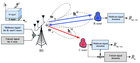
As illustrated in Fig. 1, a MIMO DFRC system is considered, which consists of a single -antenna DFRC BS, a single-antenna R-user, and a single-antenna C-user. In contract to existing work [6, 7, 8, 9, 10], where the DFRC BS detects the R-user located within the angles of interest while only communicating with the C-user, we consider mixed multicast-unicast transmission. To be more specific, two different types of messages have to be sent by the BS, one for both the R- and C-users, namely the multicast signal, while the unicast signal is only intended for the C-user. It is worth mentioning that this mixed multicast-unicast transmission represents the evolution of DFRC from isolation to integration. For instance, the multicast signal can be employed for broadcasting group-oriented system configurations and automatic software updates, which are requested both by the R- and C-users. By contrast, the unicast signal consists of personalized voice and video traffic intended for the C-user, which is not relevant for the R-user. To support this novel concept for DFRC, we propose a BB NOMA-aided joint Rad-MU-Com framework. In the following, the communication model and radar model of the proposed system will be introduced.
II-A1 BB NOMA-aided MU-Communication Model
For supporting our mixed multicast-unicast based MIMO DFRC system, the BB NOMA scheme of [11] is employed. Explicitly, the BS employs different BFs for transmitting the multicast signal intended for both R- and C-users and for the unicast signal only intended for the C-user, where the pair of signals are multiplexed in the power domain. Let and denote the multicast signal and the unicast signal at the time index , respectively. Therefore, the corresponding transmitted superimposed signal at the th time index is given by
| (1) |
where and represents the BFs designed for transmitting the multicast and unicast information symbols, respectively. Without loss of generality, we assume that the multicast and unicast signals are statistically independent of each other and we have and . Let and denote the BS-R-user channel and the BS-C-user channel, respectively, which are assumed to be perfectly estimated. For the R- and C-users, the signal received at time index can be respectively expressed as
| (2) |
| (3) |
where and denote the additive white Gaussian noise (AWGN) of the R- and C-users at the time index , respectively. Similar to the “strong” user in the conventional twin-user downlink NOMA transmission [26], the potentially stronger multicast signal is detected first at the C-user. Then, the remodulated multicast signal is subtracted from the composite received signal, automatically leaving the interference-free decontaminated unicast signal behind. As a result, the achievable rate for the multicast message at the C-user is given by
| (4) |
After subtracting the remodulated multicast signal from the composite received signal by SIC, the achievable rate for the unicast signal at the C-user is given by
| (5) |
Similar to the “weak” user in the conventional twin-user downlink NOMA transmission [12], the R-user directly detects the multicast signal by treating the unicast signal as noise. Therefore, the achievable rate for the multicast message can be expressed as
| (6) |
The rate of the multicast signal is limited by the lower one of the pair of communication rates, which is given by
| (7) |
II-A2 BB NOMA-aided Radar Detection Model
According to [6], the above superimposed communication signals can also be exploited as radar probing waveforms, i.e., each transmitted information symbol can also be considered as a snapshot of a radar pulse. Therefore, the radar beam pattern design is equivalent to the design of the covariance matrix of the transmitted signal, , which is given by
| (8) |
Then, the transmit beam pattern used for radar detection can be expressed as
| (9) |
where denotes the steering vector of the transmit antenna array, is the detection angle, represents the antenna spacing, and is the carrier wavelength.
Remark 1.
The main benefits of the proposed BB NOMA-aided joint Rad-MU-Com framework can be summarized as follows. Firstly, the employment of NOMA ensures the quality of the unicast transmission (which is usually data-hungry) for the C-user, since the inter-signal interference is canceled by SIC, see (5). Secondly, despite the presence of interference, the rate-requirement of both the R- and C-users can be readily guaranteed as a benefit of the power sharing provided by NOMA, see (4) and (6). Thirdly, the different BFs used in our BB NOMA structure provide additional degrees-of-freedom (DoFs) for our radar beam pattern design, see (8). Last but not least, NOMA facilitates double spectrum sharing between both the multicast and unicast as well as between radar and communication systems, thus further enhancing the SE.
Remark 2.
The joint Rad-MU-Com concept may also be facilitated by existing conventional transmission schemes. For example, the multicast and unicast signals can be successively transmitted via different time slots while detecting the R-user target, namely by a time division multiple access (TDMA) based Rad-MU-Com system. Moreover, the multicast and unicast can be transmitted via conventional BFs dispensing with SIC [6, 7, 8, 9, 10] while detecting the R-user target, namely by a CBF-No-SIC based Rad-MU-Com system. These options will serve as the benchmark schemes in our performance comparisons of Section IV.
II-B Problem Formulation
Before formulating the associated optimization problem, we first introduce the concept of the ideal radar beam pattern, which can be obtained by solving the following least-squares problem [6, 13]:
| (10a) | ||||
| (10b) | ||||
| (10c) | ||||
| (10d) | ||||
where denotes an angular grid covering the detector’s angular range in , is the corresponding steering vector, represents the desired ideal beam pattern gain at , is a scaling factor, is the maximum transmit power budget at the MIMO DFRC BS, and is the waveform’s covariance matrix, when only the MIMO radar is considered. It can be readily verified that the ideal radar beam pattern design problem of (10) is convex, which can be efficiently solved. Let and denote the optimal solutions of (10). The corresponding objective function value characterizes the minimum beam pattern error between the desired ideal beam pattern gain and the radar-only beam pattern gain. However, for supporting both the communication and radar functions in the MIMO DFRC system considered, a radar performance loss will occur. In the following, will be used as a performance benchmark for quantifying the radar performance loss in the joint Rad-MU-Com system design.
Given our BB NOMA-aided joint Rad-MU-Com framework and the radar performance benchmark , we aim for maximizing the unicast rate achieved at the C-user, while satisfying the minimum rate requirement of multicast communication at both the R- and C-users as well as achieving the desired beam pattern for radar detection. The resultant optimization problem can be formulated as follows:
| (11a) | ||||
| (11b) | ||||
| (11c) | ||||
| (11d) | ||||
where represents the minimum rate requirement of multicast, and is the maximum tolerable radar beam pattern mismatch ratio between the beam pattern error achieved in the joint Rad-MU-Com system (i.e., ) and the minimum one (i.e., ) obtained by the radar-only system.
III Proposed Solution
The main challenge in solving problem (11) is that the objective function and the left-hand-side (LHS) is not concave with respect to the optimization variables. To address this issue, we define and , which satisfy that , , , and . Then, problem (11) can be reformulated as follows
| (12a) | ||||
| (12b) | ||||
| (12c) | ||||
| (12d) | ||||
| (12e) | ||||
| (12f) | ||||
where (12b) and (12c) are arranged from (11b). Furthermore, we defined , , and . Now, the non-convexity of the reformulated problem (12) only lies in the rank-one constraint (12e). To tackle this obstacle, a popular technique is to use semidefinite relaxation (SDR) [6]. Explicitly, we firstly solve the problem by ignoring the rank-one constraint and then apply the Gaussian randomization method for constructing a rank-one solution, if the resultant solution is not of rank-one. However, considerable performance erosion may occur due to the reconstruction. On the other hand, it cannot be guaranteed that the reconstructed rank-one solution is still feasible in terms of satisfying all other constraints of the original problem (e.g., (11c), (12b), and (12c)). As a remedy, a double-layer penalty-based iterative algorithm is proposed for gradually finding a near-optimal rank-one solution.
To begin with, the non-convex rank-one constraint (12e) is equivalent to the following equality constraints:
| (13a) | ||||
| (13b) | ||||
where and denote the nuclear norm and spectral norm of the matrix, respectively. Let us consider as an example. It can be verified that, for any and , the above equality constraint is only satisfied, when the matrix is of rank-one. Otherwise, we always have .
To solve problem (12), we employ the penalty-based method of [14] by introducing the transformed equality constraints for and as a penalty term into the objective function of (12), yielding the following optimization problem:
| (14a) | ||||
| (14b) | ||||
where is the penalty factor, which penalizes the violation of the equality constraints (13a) and (13b), i.e., when and are not of rank-one. Since the maximization of is equivalent to maximizing the corresponding received signal strength of , we drop the function in the objective function of (14) for simplicity. Despite relaxing the equality constraints in problem (14), it may be readily verified that the solutions obtained will always satisfy the equality constraints (i.e., have rank-one matrices), when (). However, if we firstly initialize with a sufficiently small value, the objective function’s value of (14) tends to be dominated by the penalty term introduced, thus significantly degrading the efficiency of maximizing . To facilitate efficient optimization, we can initialize with a sufficiently large value to find a good starting point, and then gradually reduce to a sufficiently small value. As a result, feasible rank-one matrix solutions associated with a near-optimal performance can eventually be obtained. In the following, we will present the details of the double-layer penalty-based algorithm for solving problem (14). In the inner layer, the optimization problem for a given is solved iteratively by employing successive convex approximation (SCA) [15] until convergence is reached. In the outer layer, the penalty factor, , is gradually reduced from a sufficiently large value to a sufficiently small one.
III-1 Inner Layer: Solving Problem (14) for A Given
Note that for a given , the non-convexity of (14) manifests itself in that the second term of each penalty term is non-convex, i.e., and . However, they are concave functions with respect to both and . By exploiting the first-order Taylor expansion, their upper bounds can be respectively expressed as follows:
| (15d) | ||||
| (15h) | ||||
where and denote given points during the th iteration of the SCA method, while and represent the eigenvector corresponding to the largest eigenvalue of and , respectively.
Accordingly, by exploiting the upper bounds obtained, problem (14) can be approximated by the following convex optimization problem:
| (16a) | ||||
| (16b) | ||||
The above convex optimization problem can be efficiently solved by using existing standard convex problem solvers such as CVX [16]. Therefore, for a given , problem (16) is iteratively solved until the fractional reduction of the objective function’s value in (16) falls below the predefined threshold, , when convergence is declared.
III-2 Outer Layer: Reducing the Penalty Factor
In order to satisfy the equality constraints (13a) and (13b), in the outer layer, we gradually update the value of towards a sufficiently small value as follows:
| (17) |
where is a constant scaling factor, which has to be carefully selected for striking performance vs. complexity trade-off. For example, a larger allows us to explore more potential candidate solutions, thus ultimately achieving a higher final performance. This, however, in turn requires more outer iterations hence imposing a higher complexity.
III-3 Overall Algorithm and Complexity Analysis
Based on the above discussion, the proposed double-layer penalty-based procedure is summarized in Algorithm 1. The termination of the proposed algorithm depends on the violation of the equality constraints, which is expressed as follows:
| (18) |
where represents the maximum tolerable value. Upon reducing , the equality constraints will finally be satisfied with the accuracy of . According to [15], the proposed double-layer penalty-based algorithm is guaranteed to converge to a stationary point of the original problem (11).
The main complexity of Algorithm 1 arises from iteratively solving problem (16). Since problem (16) is a standard semidefinite program (SDP), the corresponding complexity is of the order of [17]. Therefore, the overall complexity of Algorithm 1 is , where and denote the number of inner and outer iterations required for the convergence of Algorithm 1, respectively.
IV Numerical Results
In this section, we provide numerical results obtained by Monte Carlo simulations for characterizing the proposed NOMA-aided joint Rad-MU-Com frameworks. In particular, we assume that the DFRC BS employs a uniform linear array (ULA) with half-wavelength spacing between adjacent antennas. The channel between the BS and the R-user is assumed to have pure line-of-sight (LoS) associated with the path loss of , while between the BS and C-user it is assumed to obey the Rayleigh channel model with the path loss of [6, 10], where is the path loss at the reference distance meter (m), and and represents the distance from the BS to the R-user and to the C-user, respectively. The parameters adopted in simulations are set as follows: dB, m, and m. The noise power in the receiver of users is assumed to be the same, which is set to dBm. The transmit-signal-to-noise-ratio (SNR)111Using the transmit-SNR is unconventional, because it is given by the ratio of the transmit power and the receiver noise, which are quantities measured at different points. This quantity is however beneficial for our joint Rad-Com problem, where the optimum transmit power is assigned to each user for satisfying their individual rate requirements under the idealized simplifying assumption that they have perfect capacity-achieving receivers relying on powerful capacity-achieving channel codes. This is because the optimization problem of our specific system was formulated for maximizing the unicast performance at a given transmit power, while satisfying specific constraints imposed both on the multicast rate and on the radar beam pattern. is considered in the simulations, which is given by . The initial penalty factors of Algorithm 1 is set to , the convergence threshold of the inner layer is set to , and the algorithm’s termination threshold of the equality constraints is set to . The numerical results were obtained by averaging over 200 channel realizations.
To obtain the actual true beam pattern, namely of problem (10), the desired beam pattern, , is defined as follows:
| (22) |
where denotes the actual true angles to be detected, which are determined by the location of R-users, and denotes the width of the desired beam, which is set to in the simulation. For performance comparison, we consider two benchmark schemes, which have been discussed in Remark 2.
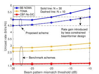
In Fig. 4, we investigate the unicast rate, , achieved versus the maximum tolerable beam pattern mismatch, . We set dB (i.e., dBm) and bit/s/Hz. As seen in Fig. 4, the unicast rate obtained by all schemes increases as increases. This is indeed expected, since lager values impose looser constraints on the BF design, which provides higher DoFs, hence enhancing the unicast performance. Moreover, a higher leads to a higher unicast rate due to the enhanced array gain and spatial DoFs. By comparing the three Rad-MU-Com schemes presented, it may be observed that the proposed BB NOMA+Rad-MU-Com scheme achieves the best performance. This is because on the one hand, employing SIC in NOMA mitigates the inter-signal interference compared to the CBF-No-SIC+Rad-MU-Com scheme, thus improving the unicast performance achieved at the C-user. On the other hand, the power-domain resource sharing and the employment of two different BFs allows NOMA to achieve a higher performance than the TDMA+Rad-MU-Com scheme. Moreover, despite employing a single BF, the TDMA+Rad-MU-Com scheme can deliver both types of messages in an interference-free manner, while carrying out radar detection. Therefore, the TDMA+Rad-MU-Com scheme outperforms the CBF-No-SIC+Rad-MU-Com scheme, whose performance is significantly degraded by the inter-signal interference. It can also be observed that the performance gain obtained by NOMA is more noticeable when increases. The above results verify the efficiency of the proposed BB NOMA+Rad-MU-Com framework.
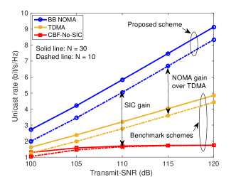
In Fig. 4, we present the unicast rate, , achieved versus the transmit-SNR, . We set bit/s/Hz and dB. It can be observed that the unicast rate of all schemes increases upon increasing . However, in contrast to both NOMA and TDMA, the rate enhancement of CBF-No-SIC attained upon increasing becomes negligible and the unicast rate is seen to be bounded by a certain value. This is because when the inter-signal interference is not mitigated, CBF-No-SIC becomes interference-limited, when the transmit power is high. Moreover, it can also be seen from Fig. 4 that the rate enhancement attained by NOMA upon increasing is more significant than for TDMA, since NOMA benefits from a flexible resource allocation scheme.
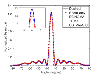
In Fig. 4, we plot the transmit beam pattern obtained by the three schemes for one random channel realization. We set , dB, bit/s/Hz, and dB. In particular, the desired beam pattern is obtained according to (22) and the beam pattern of the radar-only system is obtained by solving problem (10). As illustrated in Fig. 4, the beam pattern obtained by NOMA closely approaches that of the radar-only system, while the beam pattern mismatch of TDMA and CBF-No-SIC becomes more noticeable. Observe in Figs. 4 and 4 that given the same accuracy requirement of the radar beam pattern, the proposed BB NOMA+Rad-MU-Com scheme achieves higher communication performance than the other benchmark schemes. The above results also confirm the effectiveness of the proposed BB NOMA+Rad-MU-Com framework.
V Conclusions
A novel BB NOMA-aided joint Rad-MU-Com framework has been proposed, where a MIMO DFRC BS transmits superimposed multicast and unicast messages to the R- and C-users, while detecting the R-user target. Specifically, a BF optimization problem was formulated for enhancing the unicast performance, while satisfying both the multicast rate and the radar beam pattern requirements. To solve this problem, a penalty-based iterative algorithm was developed to find a near-optimal solution. The numerical results revealed that a higher unicast performance can be achieved by the proposed BB NOMA-aided joint Rad-MU-Com schemes than by the TDMA based scheme and the scheme without SIC.
References
- [1] Cisco, “Cisco visual networking index: Global mobile data traffic forecast update 2017-2022 white paper,” 2019.
- [2] F. Liu, C. Masouros, A. P. Petropulu, H. Griffiths, and L. Hanzo, “Joint radar and communication design: Applications, state-of-the-art, and the road ahead,” IEEE Trans. Commun., vol. 68, no. 6, pp. 3834–3862, 2020.
- [3] I. S. Merill, Introduction to radar systems. New York, NY, USA: McGraw-Hill, 2001.
- [4] N. C. Luong, X. Lu, D. T. Hoang, D. Niyato, and D. I. Kim, “Radio resource management in joint radar and communication: A comprehensive survey,” IEEE Commun. Surv. Tut., vol. 23, no. 2, pp. 780–814, 2021.
- [5] A. Hassanien, M. G. Amin, E. Aboutanios, and B. Himed, “Dual-function radar communication systems: A solution to the spectrum congestion problem,” IEEE Signal Process. Mag., vol. 36, no. 5, pp. 115–126, 2019.
- [6] F. Liu, C. Masouros, A. Li, H. Sun, and L. Hanzo, “Mu-MIMO communications with MIMO radar: From co-existence to joint transmission,” IEEE Trans. Wireless Commun., vol. 17, no. 4, pp. 2755–2770, 2018.
- [7] F. Dong, W. Wang, Z. Hu, and T. Hui, “Low-complexity beamformer design for joint radar and communications systems,” IEEE Commun. Lett., vol. 25, no. 1, pp. 259–263, 2021.
- [8] X. Liu, T. Huang, N. Shlezinger, Y. Liu, J. Zhou, and Y. C. Eldar, “Joint transmit beamforming for multiuser MIMO communications and MIMO radar,” IEEE Trans. Signal Process., vol. 68, pp. 3929–3944, 2020.
- [9] F. Liu, L. Zhou, C. Masouros, A. Li, W. Luo, and A. Petropulu, “Toward dual-functional radar-communication systems: Optimal waveform design,” IEEE Trans. Signal Process., vol. 66, no. 16, pp. 4264–4279, 2018.
- [10] N. Su, F. Liu, and C. Masouros, “Secure radar-communication systems with malicious targets: Integrating radar, communications and jamming functionalities,” IEEE Trans. Wireless Commun., vol. 20, no. 1, pp. 83–95, 2021.
- [11] Y. Liu, H. Xing, C. Pan, A. Nallanathan, M. Elkashlan, and L. Hanzo, “Multiple-antenna-assisted non-orthogonal multiple access,” IEEE Wireless Commun., vol. 25, no. 2, pp. 17–23, 2018.
- [12] Y. Liu, Z. Qin, M. Elkashlan, Z. Ding, A. Nallanathan, and L. Hanzo, “Nonorthogonal multiple access for 5G and beyond,” Proc. IEEE, vol. 105, no. 12, pp. 2347–2381, 2017.
- [13] D. R. Fuhrmann and G. San Antonio, “Transmit beamforming for MIMO radar systems using signal cross-correlation,” IEEE Trans. Aerosp. Electron. Syst., vol. 44, no. 1, pp. 171–186, 2008.
- [14] J. Nocedal and S. Wright, Numerical Optimization. New York, NY, USA: Springer, 2006.
- [15] Q. T. Dinh and M. Diehl, “Local convergence of sequential convex programming for nonconvex optimization,” Recent Advances in Optimization and its Applications in Engineering, Springer, 2010.
- [16] M. Grant and S. Boyd, “CVX: Matlab software for disciplined convex programming, version 2.1,” [Online]. Available:http://cvxr.com/cvx, 2014.
- [17] Z. Luo, W. Ma, A. M. So, Y. Ye, and S. Zhang, “Semidefinite relaxation of quadratic optimization problems,” IEEE Signal Process. Mag., vol. 27, no. 3, pp. 20–34, May 2010.