Centralized Hierarchical Coded Caching Scheme over Two-Layer Networks ††thanks: Yun Kong and Minquan Cheng are with Guangxi Key Lab of Multi-source Information Mining Security, Guangxi Normal University, Guilin 541004, China. (e-mail: yunkong2022@outlook.com, chengqinshi@hotmail.com). ††thanks: Youlong Wu is with the School of Information Science and Technology, ShanghaiTech University, 201210 Shanghai, China. (e-mail: wuyl1@shanghaitech.edu.cn).
Abstract
This paper considers a hierarchical caching system where a server connects with multiple mirror sites, each connecting with a distinct set of users, and both the mirror sites and users are equipped with caching memories. Although there already exist works studying this setup and proposing coded caching scheme to reduce transmission loads, two main problems are remained to address: 1) the optimal communication load under the uncoded placement for the first hop, denoted by , is still unknown. 2) the previous schemes are based on Maddah-Ali and Niesen’s data placement and delivery, which requires high subpacketization level. How to achieve the well tradeoff between transmission loads and subpacketization level for the hierarchical caching system is unclear. In this paper, we aim to address these two problems. We first propose a new combination structure named hierarchical placement delivery array (HPDA), which characterizes the data placement and delivery for any hierarchical caching system. Then we construct two classes of HPDAs, where the first class leads to a scheme achieving the optimal for some cases, and the second class requires a smaller subpacketization level at the cost of slightly increasing transmission loads.
Index Terms:
hierarchical placement delivery array, hierarchical coded caching scheme, transmission load, subpacketization.I Introduction
With the growing data demand especially the streaming media, there exists an extreme transmission pressure during the peak traffic hours in the wireless network. It is well known that caching system is an efficient way to reduce transmission during the peak traffic hours by shifting traffic from peak to off peak hours. That is, the central server can firstly place some contents into users’ memories during the off peak traffic hours. During the peak traffic hours, the central server would only transmit the contents which have not been cached by the users. In addition, Maddah-Ali and Niesen in [1] showed that the contents cached by the users can be used to further reduce the transmission load during the peak traffic hours since these contents could generate more multicast opportunities among the users. They first introduced the centralized caching system where a single server having access to a library containing files is connected to cache-aided users whose cache size is files through an error-free shared-link. An -division coded caching scheme contains two phases. During the placement phase, each file is divided into packets, where is referred as the subpacketization, and the server places at most packets into each user’s cache without any information about users’ demands. Since the packets are directly cached by the users, this placement strategy is called uncoded placement. In the delivery phase, each user requests a file from the server randomly and the server broadcasts some coded messages to users such that all the users can decode their requesting files with the help of their cached packets. We focus on the worst case where each user requests a distinct file. The transmission amount normalized by the size of file is defined as the “transmission load”.
To further reduce the transmission load of a caching system, Maddah-Ali and Niesen proposed the first centralized coded caching scheme [1] (MN scheme) and the first decentralized coded caching scheme [2] (MN decentralized scheme) respectively. It is worth noting that when , MN scheme has the minimum transmission load under uncoded placement in [3]. However, the subpacketization of the MN scheme increases exponentially with the growing on user number . In order to design a scheme with low subpacketization, the author in [4] proposed a combination structure named placement delivery array (PDA) to simultaneously characterize the placement and delivery phase of a coded caching scheme. The MN scheme could also be depicted by PDA referred to as MN PDA. It is worth noting that MN scheme has the minimum subpacketization for the fixed minimum transmission load among all the schemes which can be realized by PDAs [5]. Besides PDA, there also exists some other combination structures to describe a coded caching scheme aiming at reducing the subpacketization level, such as [6, 7, 8], etc.
I-A Two-layer hierarchical network model
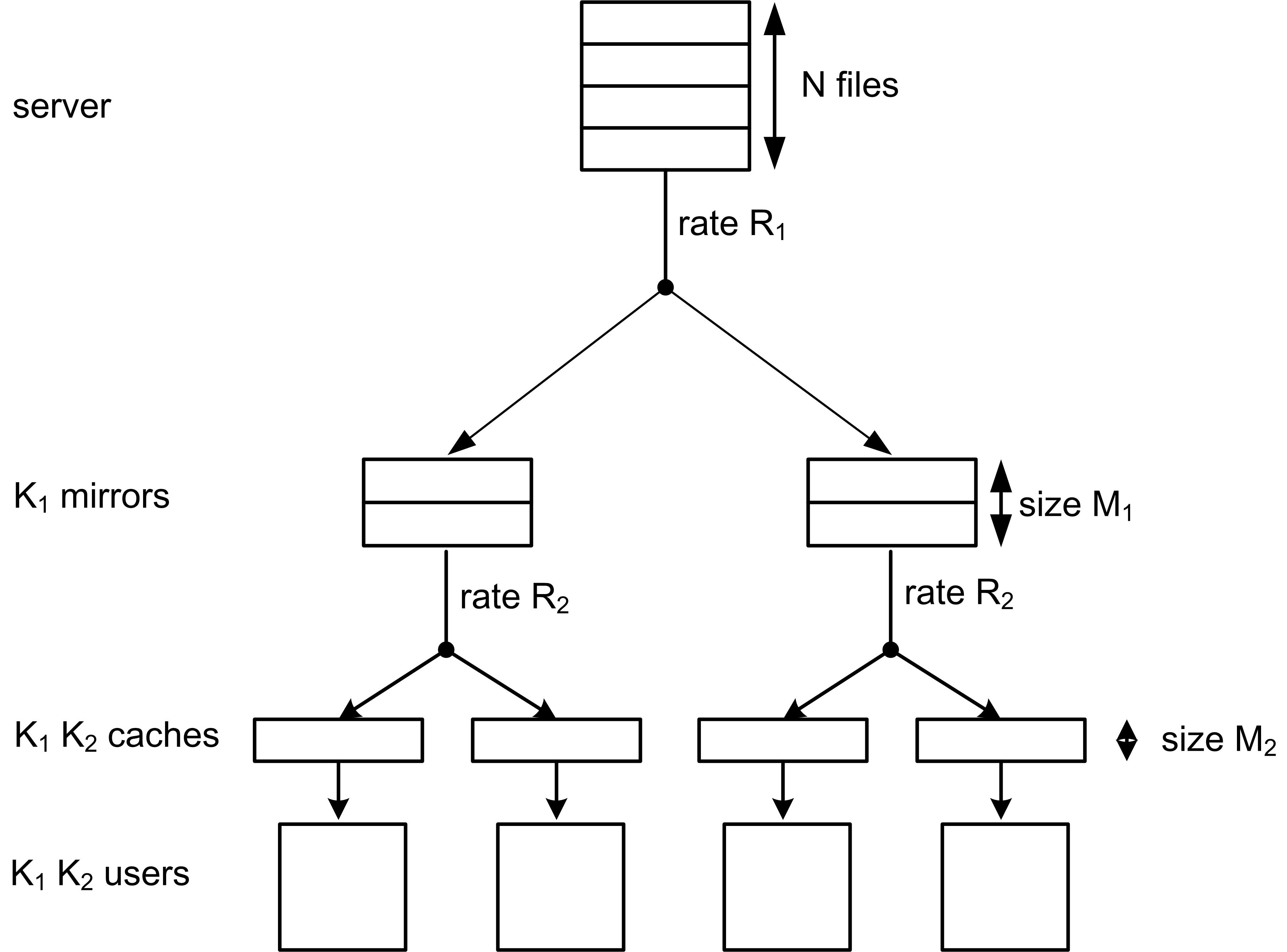
In reality, the caching systems consist multiple layers of caches in most cases, which means between the central server and the end users, there are some in-between devices, and all these devices are arranged in a tree-like hierarchy with the central server at the root node while the end users act as the leaf nodes. Between each layer, the parent node communicates with its children nodes. As illustrated in Fig. 1, a , ; , ; hierarchical caching system was first studied in [9]. That is, a two-layer hierarchical network consists of a single origin server and cache-aided mirror sites and cache-aided users where the server hosts a collection of files with equal size, each mirror site and each user have memories of size files and files respectively where , . The server is connected through an error-free shared link to each mirror site. Each mirror site is connected through an error-free broadcast link to users and each user is connected to only one mirror site.
Due to the complexity of the above hierarchical caching system, there are only a few studies in [9, 10, 11]. In fact, all the existing schemes consist of two-subsystem model controlled by two parameters , where the first subsystem includes the whole cache memory size of each mirror sites, an fraction of each file and a fraction of users’ cache memory size, and the second subsystem includes the rest fraction of each file and a fraction of users’ cache memory size. In [9], the authors directly used the MN decentralized scheme in each layer. Then the requested files are built in each layer, so it results in a high transmission load of . This scheme is referred as KNMD scheme. Without building the whole file in each layer, the authors in [10] proposed a hybrid scheme ( the ZWXWL scheme) based on two MN schemes for the two layers, so it has a lower transmission load of and its achieves the minimum transmission load under uncoded placement. However, the ZWXWL scheme ignores the usefulness of users’ cache in the second layer when decoding the messages sent from the server. The author in [11] proposed an improved scheme (the WWCY scheme) by utilize two MN schemes. the WWCY scheme also achieves the minimum load of under uncoded placement, while the load of the first layer is smaller than the ZWXWL scheme. There are some other works on hierarchical caching model, such as the coded placement for hierarchical cache-enabled network [12, 13], the intension between two layers transmission loads [14] and the topology where there are some users directly connected to the server [15] etc.
I-B Contribution and paper organization
In this paper we focus on the hierarchical caching model in [9]. From the introduction in the above subsection, the existing schemes already have a good performance on , while designing a scheme aiming at decreasing still remains open. Further, [9, 10, 11] all utilize the MN scheme or MN decentralized scheme, whose subpacketization increases exponentially with the growing on user number, so it is meaningful to design the scheme with minimizing the transmission load for the first layer or reducing the subpacketization. According to the above points, in this paper we obtain the following main results.
-
•
Inspired by the concept of PDA, we propose a new combination structure referred to as hierarchical placement delivery array (HPDA), which could be used to characterize the placement and delivery phase of a hierarchical coded caching scheme. So designing a hierarchical coded caching scheme is transformed to constructing an appropriate HPDA.
-
•
We propose a class of HPDA by dividing a MN PDA into several subarrays. Then we have a class of hierarchical coded caching schemes which achieve the lower bound of the first layer transmission load .
-
•
We provide a general hybrid construction of HPDA based on any two PDAs. So we can get a scheme with flexible subpacketiztion when we choose the base PDAs with low subpacketiziations. In addition if the base PDAs are MN PDAs, then the scheme realized by our HPDA is exactly the scheme in [11].
The rest of this paper is organized as follows. The hierarchical caching model and some preliminary results are introduced in Section II. We review PDA and introduce the structure of HPDA in Section III. The main results and performance analysis are listed in Section IV. The proofs of our main results are proposed in Sections V and VI. Finally we conclude this paper in Section VII.
I-C Notations
The following notations are used in this paper.
-
•
For any positive integers and with , let , and . Let , for any positive integer .
-
•
Given an array with alphabet , we define and for any integer , where .
II Problem Definitions and Prior Works
In this section, we first describe the hierarchical caching system, and then review some existing works that motivate our work in this paper.
II-A Hierarchical Caching System
Consider a hierarchical caching system as shown Fig. 1, which consists of a single server, mirror sites and users. The server connects with mirror sites via a shared link and each mirror site connects with users via another shared link. The server contains a collection of files, denoted by , each of which is uniformly distributed over . Each mirror site and user has memory size of and bits, respectively, for some , .
Denote the -th user attached to the -th mirror site as , for , and the set of users attached to the -th mirror site as . An -division coded caching scheme contains two phases:
-
•
Placement phase: During the off peak traffic time, each file is divided into packets with equal size, i.e., where is divisible by . Then the mirror sites and users cache some packets of each file. In other words, we consider the uncoded cache placement. Denote the contents cached by the mirror site and user as and , respectively. During the placement phase, we assume the server is not aware of the users’ requests.
-
•
Delivery phase: During the peak traffic time, each user requests one file from the file library randomly. The demand vector is denoted by , i.e., user , requests the -th file where . The messages sent in the hierarchical network contain two parts:
-
–
The messages sent by the server: Based on the cached contents and the demand vector , the server broadcasts a message including packets to mirror sites.
-
–
The messages sent by mirror site: Based on the messages sent by the server, the locally cached contents and the demand vector , each mirror site broadcasts a coded messages of size packets to its attached users (i.e., users in ), such that all the users can recover their requested files.
-
–
In this paper, we consider the worst case where each user requests a distinct file. Given a hierarchical caching system described above, the transmission loads in terms of files for the first and second layer are defined as
respectively. Define the optimal transmission loads of the first and second layer, denoted by and , as the minimum transmission load of and under uncoded placement respectively, such that all users can recover their requesting files.
II-B Prior Works
The authors in [9] first studied this hierarchy caching system and proposed a decentralized hierarchical coded caching scheme, namely the KNMD scheme, based on the decentralized coded caching scheme for cache-aided broadcast network [2]. The main idea of KNMD scheme is to divide the system into two independent subsystems for some fixed parameters , . The first subsystem includes the entire cache memory of each mirror site and a fraction of each user’s cache memory, which is responsible for caching and delivering the parts of each file. The second subsystem includes the remaining fraction of each user’s cache memory, and is responsible for caching and delivering the left parts of each file. In the first subsystem, the server first sends coded signals to mirror sites using the single-layer MN decentralized coded caching scheme [2] where each mirror site requests distinct files, without considering users’ cache contents. Then each mirror site decodes its intend files and applies again the single-layer decentralized coded caching scheme to broadcast a message to its attached users to satisfy their demands. In the second sub-system, the server ignores the cache contents of mirror sites, and applies the single-layer decentralized coded caching scheme to directly serve users each of caching size . By extending this scheme to the case with centralized data placement [1], we obtain the transmission loads of the first and second layer, denoted by and , as
| (1) |
for some and , where
is the transmission load of the MN scheme for any memory ration .
In the KNMD scheme, the server sends messages to the mirror sites while ignoring the users’ cache contents. This means that the server may send some information which has already been stored by the users, leading to redundant communication cost in the first layer. To address this problem, [11, Section VI] improved the transmission load of the first layer of DHCC scheme by concatenating two MN schemes, whose transmission loads of the first and second layer, denoted by and , are
| (2) |
Note that under uncoded placement, schemes in [9] and [11, Section VI] both achieve the optimal transmission load of the second layer when , i.e.,
An interesting question is what is the optimal transmission load of the first layer. In this paper, we aim to find novel centralized coded caching schemes to reduce the transmission load of the first layer (i.e., ), and establish its optimal value for some regimes.
III Hierarchy Placement Delivery Array
In this section, we first briefly describe the vanilla PDA for the single-layer cache-aided broadcast network [4], and then introduce a novel PDA structure, namely HPDA, that would help characterize the placement and delivery of coded caching schemes for the hierarchical caching system in Fig. 1.
III-A Placement Delivery Array
Definition 1:
([4]) For any positive integers and , an array over alphabet set is called a PDA if it satisfies the following conditions,
The symbol “” appears times in each column;
Each integer occurs at least once in the array;
For any two distinct entries and , is an integer only if
-
a.
, , i.e., they lie in distinct rows and distinct columns; and
-
b.
, i.e., the corresponding subarray formed by rows and columns must be of the following form
Example 1:
When and , we can see that the following array is a PDA.
| (6) |
The authors in [4] showed that a PDA can be used to realize an -division coded caching scheme with and transmission load for the single-layer cache-aided broadcast network. Furthermore the seminal coded cahcing scheme proposed in [1] can be represented by a special PDA which is referred to as MN PDA. That is the following result.
Lemma 1:
(MN PDA[1]) For any positive integers and with , there exists a PDA which realizes a MN scheme with , subpacketization and transmission load .
Here we briefly review the construction of MN PDA as follows.
Construction 1:
(MN PDA[1]) For any integer , let . Then we have a array by
| (9) |
where is a bijection from to and the rows are labelled by all the subsets listed in the order from the small to large.
Finally we should point out that PDA has been widely studied. There are some schemes with lower subpacketization level based on PDA proposed in [4, 16, 17, 18, 19, 20, 21, 22, 23, 24]. In addition, the authors in [25] pointed out that all the proposed schemes in [26, 27, 28, 7, 29] could be represented by appropriate PDAs.
III-B Hierarchical Placement Delivery Array
The definition of hierarchy placement delivery array (HPDA) is given as follows.
Definition 2:
For any given positive integers , , with , and any integer sets and , , an array , where is an array consisting of and null, and is an array over , , is a hierarchy placement delivery array (HPDA) if it satisfies the following conditions:
-
B1.
Each column of has stars;
-
B2.
is a PDA for each .
-
B3.
Each integer occurs in exactly one subarray where . And for each , , ;
-
B4.
For any two entries and where , and , if is an integer then
-
–
is an integer only if ;
-
–
is an iteger only if .
-
–
For any given HPDA, when we use to indicate the data placement at mirror sites, and use to indicate data placement at the users attached to -th mirror site (i.e., users in ) and the delivery strategy at the server and mirror sites (see detailed explanation in Remark 1), a hierarchical coded caching scheme can be obtained by Algorithm 1.
First we use the following example to demonstrate the placement and delivery strategy of the hierarchal caching scheme by Algorithm 1 based on a HPDA.
Example 2:
When , , , , , , one can check that the following array is a HPDA in (10).
| (10) |
Based on and by Algorithm 1, we can get a - coded caching scheme in the following way.
- •
-
•
Delivery Phase: Assume that . From Algorithm 1, the messages sent to all users consist of two parts.
- –
-
–
The messages sent by mirror site consists of the coded packets generated by from the server and the packets cached by mirror site where , and the coded packets generated only by the packets cached by mirror site where .
From Lines 17-20 and (10), we have , so the mirror site 1 sends the coded packets :
since it can receive the coded packets from server and it has cached packets , , , , , . Then user can decode , , , and from since it has cached . Similarly, can also recover some of its required file packets from and its own cache memory respectively. Since there are coded packets sent by mirror site .
Now we see the coded packets sent by mirror site . From Lines 21-24 and (10), we have , so mirror site sends :
to users and from its own cached packets. Clearly each user can directly get the above packets and there are packets. Then the transmission amount by mirror site is , which is the transmission load of the second layer .
Actually, in (10) is obtained by Theorem 2, whose achieves the minimum load under the restriction of parameters specified by . In [9, 11], by the exhaustive computer searches for the values of and to find the minimum transmission load of the first layer under the same circumstance, we have from (1) and from (2). Clearly .
Remark 1:
From Algorithm 1 and Example 2, we have the following relationship between , HPDA and its realized -division coded caching scheme for the hierarchical coded caching problem where , .
-
•
An mirror sites-placement array consists of and null entries. The column labels represent the mirror site indices while the row labels represent the packet indices. If entry , and , then mirror site has already cached the -th packet of all the files in server. All mirror sites have the same memory ratio according to B1 of Definition 2.
-
•
An users-placement and delivery array consists of *. The column labels represent the user indices while the row labels represent the packet indices. If entry , , , , user has already cached the -th packet of all the files in server. All the users have the same memory ratio according to B of Definition 2. The integers in indicate the broadcast packets transmitted by the server, and the integers in , , represent the broadcast packets sent by the mirror site . In addition the integers in represent the multicast messages sent only by the mirror sites.
-
•
The property B2 and B4 of Definition 2 guarantee that each user can recover its requested packet, since user or mirror site has cached all the other packets in the broadcast message except the one requested by . More precisely, if entry , , , , then the -th packet of all files is not stored by user . In this case the server broadcasts a coded packet (i.e., the XOR of all the requestd packets indicated by ) to the mirror sites. Assume that the packet required by user , say , and any other packet, say , are included in the coded signal listed in Line 13 of Algorithm 1. Then we have . If , then from the Condition C of definition 1 we have because is a PDA, which means user has cached the packet . If and , then from Condition B of Definition 2 we have . This implies that mirror site has cached . From Line 19 of Algorithm 1, the coded signal , which is transmitted to user by mirror site , is generated by cancelling the by mirror site . So only contains one packet required by user and the packets which have been cached by user . Clearly user can decode its requiring packet . So the number of packets transmitted by the server is . Then the transmission load from server to mirror sites is . While if , by the Condition B of Definition 2 the mirror site has already cached all the required packets labeled by . So the mirror site can broadcast a multicast message (i.e. the XOR of all the requested packets indicated by ) to the user in . Then the number of packets transmitted simply by the mirror site is . This implies that the transmission load from mirror site to its attached users in is .
From the above investigations in Remark 1, we can obtain the following result.
Theorem 1:
Given a HPDA , we can obtain an -division coded caching scheme with , and transmission load , .
From Theorem 1, we can obtain a hierarchical coded caching scheme by constructing an appropriate HPDA. So in this paper we focus on constructing HPDA to get its realized scheme with better performance compared with the previously known results.
IV Main Results
In this section, we first present new upper bounds on the optimal transmission loads based on two classes of HPDAs, and then compare these bounds with previously known results.
Theorem 2:
For any positive integers , , , , there exists a ; ; , ; , , HPDA, which leads to an -division , ; , ; coded caching scheme with
| (11a) | |||
| (11b) | |||
| (11c) | |||
| (11d) | |||
Proof.
See the proof in Section V. ∎
Corollary 1:
For a two-level hybrid network with memory ratios satisfying (11a), the transmission load in (11c) is optimal under the uncoded data placement, i.e.,
Proof.
The memory ratios in Theorem 2 are constrained by combination numbers as shown in (11a), which means the rate may be not always achievable for general memory ratios . In order to allow flexible memory ratios, we propose the following upper bound based on a new class of HPDA.
Theorem 3:
For any PDA and PDA , there exists a ; ; , ; , , , HPDA, which leads to a coded caching scheme with memory ratios , and transmission loads
| (12) |
Proof.
See the proof in Section VI ∎
Remark 2:
In Fig. 2, we compare the following schemes: 1) the KNMD scheme [9]; 2) the WWCY scheme [11]; 3) the Scheme for Theorem 2; 4) Scheme I for Theorem 3; 5) Scheme II for Theorem 3. Note that we can also design our new hybrid schemes like the previous works [9, 11], which divide the system into two subsystems with splitting parameters (), and run the proposed schemes in the first subsystem, and the MN scheme in the second subsystem. Since the optimal and are hard to determine due to a tradeoff between and , and the second subsystem totally ignores mirror sites’ caching abilities, we only focus on schemes working in the first subsystem, i.e., compare all schemes with . Besides, due to the limitation on memory ratios (11a), it is hard to compare all schemes with general . We thus evaluate the performance of various scheme with fixed parameters , and varying parameters such that the ratios in (11a) are satisfied. More precisely, takes the value from to regularly with step size , and takes the value from to (without fixed step size but on a downward trend), which satisfies memory ratios (11a) in Theorem 2.
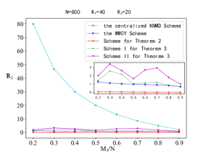
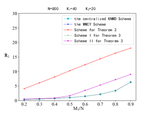
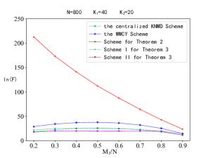
Fig. 2 plots the rate versus . We can see that applying the proposed schemes for Theorem 2 and 3 can significantly reduce the transmission load compared to the KNMD scheme. In order to have a clear view, we draw a sketch sub-figure in Fig. 2 that is without the KNMD scheme. Among all schemes, the scheme for Theorem 2 achieves the smallest , and the WWCY scheme achieves the second best performance. Note that the WWCY scheme is a special case of Theorem 3 where both and are MN PDAs, as mentioned in Remark 2. By comparing the WWCY scheme, Scheme I and Scheme II for Theorem 3, we can see that using different PDAs for and results in different transmission loads, and using MN PDA for or would reduce the transmission load than using other PDAs.
Fig. 2 compares the rate versus . It can be seen that the scheme for Theorem 2 requires the largest . In view of Fig. 2 where the scheme for Theorem 2 achieves the optimal , we obtain that there exists a tradeoff between and . In other words, minimizing may lead to the increasing on . Note that the WWCY scheme, the KNMD scheme and the Scheme I for Theorem 3 achieve the same , which is the optimal under uncoded placement, and the gap between the optimal rate and the rate of the Scheme II for Theorem 3 is almost marginal, especially when is small. Note that the curves in Fig. 2 show that increases with . This is because in general decreases with , while increases due to the relation indicated by (11a).
Fig. 2 demonstrates the subpacketization levels of various schemes. It can be seen that the Scheme for Theorem 2, which achieves the minimum , requires the highest subpacketization level, and the subpacketization level decreasing almost linearly with . The Scheme II for Theorem 3, which uses the proposed PDAs in [4] for both and , requires the lowest subpacketization level. The WWCY scheme, which uses MN-type PDAs for both and , incurs larger subpacketization level than other schemes not using MN-type PDAs. From the above, we can conclude that by choosing different types of PDAs to construct the HPDA, one can achieve a flexible tradeoff between the subpacketization level and transmission loads.
V Proof of Theorem 2
In this section, we describe how to construct a ; ; , ; , , HPDA , , , in Theorem 2 based on the array MN PDA . We partition into parts by column, i.e., . Then we have the following expressions.
| (13) | |||
| (14) | |||
| (15) |
As mentioned in Remark 1, and indicates the data placement at mirror sites and users in , respectively. Given any array, we call a row of it star row if this row contains only star entries. The construction of HPDA , , , for Theorem 2 can be briefly described as follows: To construct array , we let its element be a star entry if the -th row of is a star row, and be null otherwise. To construct the array , we simply replace all the star entries in each star row of with distinct integers, for all .
In the follows, we first use an illustrative example to show the construction of , and then present our general proof of coded caching scheme based on the HPDA in Theorem 2.
V-A Example of the Construction of HPDA in Theorem 2
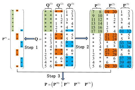
Given a MN PDA , we will use a grouping method to construct a HPDA in (10), where
| (16) | |||
The construction includes the following three steps, as illustrated in Fig. 3.
-
•
Step 1. Construction of . Because the star rows of are row , , , , , and , we fill , and for the rest entries in column of , we fill them with null. Similarly, the columns and of can be obtained by applying the same operation on and respectively. Then the resulting array is our required .
- •
-
•
Step 3. Construction of . We get a array by arranging and , and horizontally, i.e. .
V-B General Proof of Theorem 2
Given a MN PDA , , we show how to construct a ; ; , ; , , ; ; , ; , , HPDA , , , , where , , , are listed in (21) and (23) respectively. For the sake of convenience, we use a set to represent the row index of an MN PDA defined in Construction 1 and the constructed HPDA, i.e., is represented by , . The constructions of and are described as follows:
-
•
Step 1. Construction of . We construct the mirror site’s placement array by the following rule:
(20) That is, let be a star if the row of is a star row, and be null otherwise.
-
•
Step 2. Construction of . For each , is used to construct , where . Note that there are in total star rows in , , and each star row has star entries. Then we replace all these star entries in each star row of , , with consecutive integers from to to construct , and all these integers form the set as follows.
(21) -
•
Step 3. Construction of . We get an array by arranging and horizontally, i.e., .
V-B1 Parameter computations
The integer set can be directly obtained from (21), which has no intersection with .
Then we focus on . Clearly each satisfies Conditions C1 and C3 of Definition 1. Now we consider the integer set of . Recall that is a bijection from to in (9). Then for any sub-array , integer is in if and only if its inverse mapping contains at least one integer of , i.e., . So the integer set of is
| (22) |
Furthermore, after adding up the integers used for the substitution in Step 2 of , the integer set of is
| (23) |
and .
V-B2 The properties of HPDA verification
From (9) the row of is a star row if and only if all the integers of (i.e., indices of users in ) are contained by . So there are star rows, i.e., each column of has stars, satisfying Condition B of Definition 2.
From (22) we have . So is a PDA. Actually, is obtained by replacing the star entries in star row of PDA by some unique integers which have no intersection with . So is a PDA, satisfying Condition B of Definition 2.
From Step , we know that each integer in occurs only once in . Clearly the first part of Condition B holds. For any , we know row is a star row of , then from (20) we have . The second part of Condition B holds, then Condition B holds.
We can show that Condition B holds by the following reason. Assume that there are two entries , where . Then since each integer of occurs exactly once. Furthermore if is an integer, then must be the element of , otherwise it contradicts our hypothesis that is a PDA. From the construction of , only if the row indexed by of is a star row. Then from (20) we have .
From the above introduction, our expected HPDA is obtained. And the integer set is actually the integer set , whose cardinality is . Then by Theorem 1, the transmission loads
can be directly obtained.
VI Proof of Theorem 3
In this section, we describe how to construct the ; ; , ; , , , HPDA , , , in Theorem 3 based on any PDA and PDA , where
is a couple indicating the -th row and where , , , . The construction of HPDA , , , for Theorem 3 can be briefly described as follows: Given two PDAs, denoted by , respectively, is obtained by deleting all the integers of and then simply expanding each row of it, and , , is obtained by using a hybrid method, in which acts as an outer array and the inner arrays are simply constructed from .
In the follows, we first give an illustrative example to show the construction of based on two MN PDAs, and then present our general proof of coded caching scheme based on the HPDA in Theorem 3.
VI-A Example of the Construction of HPDA in Theorem 3
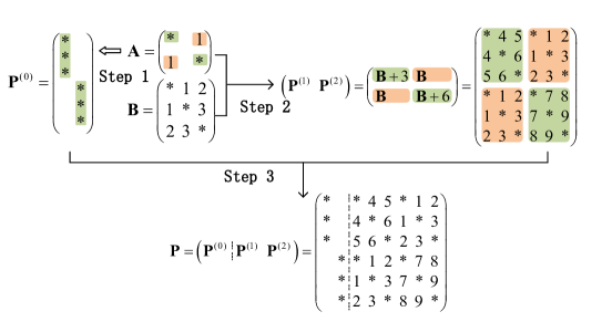
Given a MN PDA and a MN PDA where
| (29) |
We will use a hybrid method to construct a , HPDA where
| (30) |
through the following three steps, as illustrated in Fig. 4.
-
•
Step 1. Construction of for mirror sites. We can get a array by deleting all the integer entries of and then expanding each row times111 This is the row number of the inner structure array which will be introduced in Step 2..
-
•
Step 2. Construction of for users. We replace the integer entries and by , and replace by , respectively to get
(31) -
•
Step 3. Construction of . We get a array by arranging and horizontally, i.e., .
Now we verify that the construction above leads to a HPDA defined in Definition 2.
VI-B General Proof of Theorem 3
In this subsection, we will prove Theorem 3 by constructing a ; ; , ; HPDA , , , with any PDA and PDA , where and will be proposed in (47) and (48) respectively. The constructions of and are described as follows:
-
•
Step 1. Construction of . We can get an array by deleting all the integers in and expanding each row by times. Then each entry can be written as follows.
(34) -
•
Step 2. Construction of . The main idea of constructing is replacing the entries of by inner array and adjusting its integers. As consists of integer-type entries and star-type entries, our construction consists of the following two parts. Firstly we replace each integer entry by an array
(35) Secondly we replace each star entry by an array
(36) where represents the order of the row labels from up to down among all the star entries in -th column of .
Here we take in Fig. 4 as an example. As , we have in (29). While , , we have and in (43), where
(43) From the above example, obviously the integer sets in , and have no common integer, and we can generalize the investigation to the general cases, as illustrated in Lemma 2.
Lemma 2:
For any integers , , , , and , we have the following statements on the integer sets in , , and .
-
–
The integer sets in and have no common integer if and only if ;
-
–
When , the integer sets in and have no common integer if and only if ;
-
–
When , the integer sets in and have no common integer;
-
–
When , the integer sets in and have no common integer;
By Lemma 2, each entry in is determined uniquely and can be written as follows,
(46) -
–
-
•
Step 3. Construction of . We get an array by arranging and horizontally, i.e., ,,,.
VI-B1 Parameter computations
For a PDA, we define as the integer set containing all the integers in the -th column where and . Firstly we consider the integer set , which is the union set of the integer set of each . There are in total stars in , then from and Lemma 2 we have
| (47) |
Obviously the cardinality of is .
Secondly we focus on , i.e., the integer set of for each . From (35), is composed of inner arrays and inner arrays . So the integer set is actually the union set of all integer sets of the inner arrays. Then from (35), (36) and Lemma 2, the integer set of is
| (48) |
. Because , according to Lemma 2, all the integer sets of inner arrays used for composing do not have any common integer, so we have .
VI-B2 The properties of HPDA verification
Because there are stars in each column of , from (34) each column of has exactly stars, satisfying Condition B of Definition 2.
Then we focus on Condition B, i.e., is a , , , PDA. Because is composed of inner arrays, each column of has stars. So Condition C of Definition 1 holds. In the above we have , obviously C of Definition 1 holds. Because all the arrays defined in (35) and (36) satisfy Condition C of Definition 1 and by Lemma 2, the intersection of the integer sets of any two of the inner arrays is empty, then each also satisfies the Condition C. Thus, each is a PDA.
Now consider Condition B. Recall that all the integers in are generated from (36). If , by the third statement of Lemma 2, each integer in only exists in one . When the entry , from (46) and (34) we have , . Thus, Condition B holds.
Finally we consider the Condition B. For any integers , , , and any couples , , assume that is an integer. By Lemma 2, the case , is impossible since the intersection of the integer sets of related inner arrays is empty. So we only need to consider the case where , , and there are three conditions:
- •
- •
- •
From the above discussion, the Condition B of Definition 2 holds. Thus, is our expected HPDA.
The integer set is the union set of integer sets in inner arrays , , then we have . From Theorem 1 we have the load for the first layer
and the load for the second layer
VII Conclusion
In this paper, we studied the hierarchical network model and introduced a new combination structure, referred as HPDA, which can be used to characterize both the placement and delivery strategy of the coded caching scheme. So the problem of designing a scheme for hierarchical network is transformed into constructing an appropriate HPDA. Firstly we propose a class of HPDAs, which achieves the lower bound of the first layer transmission load for non-trivial cases, by dividing the MN PDAs into several equal size groups. Due to the limitation of the system parameters in this class of HPDAs, we then proposed another class of HPDAs via a hybrid construction of two PDAs. Consequently, using any two PDAs, a new HPDA can be obtained which allows flexible system parameters and has a smaller subpacketization level compared with our first class of HPDAs.
Appendix A Lower Bound of
Recall that during the data placement placement, the cached contents at user and mirror site are and , respectively.
Now we introduce an enhanced system where each user already knows the cache contents of its connected mirror site. For this enhanced system, denote the cache contents of the user as . In uncoded placement scenarios, each file can be viewed as a collection of packets as , where user stores if . Consider one permutation of denoted by , , and one demand vector where if or . We then construct a genie-aided super-user with cached content
| (49) | |||||
The genie-aided super-user is able to recover from , where and are the signals sent by the server and mirror site , respectively. Thus, we have
| (50) |
where the last equality holds because contains all mirrors’ contents , leading to for all .
Next we introduce a more powerful enhanced system where each user has a caching size of bits, and denote its cached content as . Note that this enhanced system can only result in smaller communication loads in and than that of the first enhanced system. This is because in the new enhanced system each users is able to cache any set of sub-files of bits, including the caching strategy of the first enhanced system . We then construct a new genie-aided super-user with cached content
| (51) | |||||
Due to the stronger caching ability of the new genie-aided super-user, we have
| (52) |
where (a) holds by (50). From (52), we obtain that
| (53) |
This is equivalent to a single-layer coded caching system where the server connects -user each equipped with cache memory of bits. Now we follow the method in [30] to prove the lower bound of .
Summing all the inequalities in the form of (53) over all permutations of users and all demand vectors in which users have distinct demands, we obtain that
| (54a) | |||
| where | |||
| (54b) | |||
Also, we have the following conditions due to the constraints on the file size and memory size
| (55) |
Combining (54) and (55) and by Fourier Motzkin elimination, we obtain the lower bound of
Appendix B Proof of Lemma 2
Without loss of generality we assume that . From (35) the first statement holds since the minimum integer of the integer set of minus the maximum integer of the integer set of is
While if , and are the same array.
Without loss of generality we assume that . From (36) the second statement holds since the minimum integer of the integer set of minus the maximum integer of the integer set of is
While if , and are the same array.
Without loss of generality we assume that . From (36) the third statement holds since the minimum integer of the integer set of minus the maximum integer of the integer set of is
References
- [1] M. A. Maddah-Ali and U. Niesen, “Fundamental limits of caching,” IEEE Trans. Infor. Theory, vol. 60, no. 5, pp. 2856–2867, 2014.
- [2] ——, “Decentralized coded caching attains order-optimal memory-rate tradeoff,” IEEE/ACM Trans. Network, vol. 23, no. 4, pp. 1029–1040, 2015.
- [3] K. Wan, D. Tuninetti, and P. Piantanida, “An index coding approach to caching with uncoded cache placement,” IEEE Transactions on Information Theory, vol. 66, no. 3, pp. 1318–1332, 2020.
- [4] Q. Yan, M. Cheng, X. Tang, and Q. Chen, “On the placement delivery array design for centralized coded caching scheme,” IEEE Trans. Infor. Theory, vol. 63, no. 9, pp. 5821–5833, 2017.
- [5] M. Cheng, J. Jiang, X. Tang, and Q. Yan, “Some variant of known coded caching schemes with good performance,” IEEE Transactions on Communications, vol. 68, no. 3, pp. 1370–1377, 2020.
- [6] C. Shangguan, Y. Zhang, and G. Ge, “Centralized coded caching schemes: A hypergraph theoretical approach,” IEEE Transactions on Information Theory, vol. 64, no. 8, pp. 5755–5766, 2018.
- [7] Q. Yan, X. Tang, Q. Chen, and M. Cheng, “Placement delivery array design through strong edge coloring of bipartite graphs,” IEEE Communications Letters, vol. 22, no. 2, pp. 236–239, 2018.
- [8] M. Cheng, J. Li, X. Tang, and R. Wei, “Linear coded caching scheme for centralized networks,” IEEE Transactions on Information Theory, vol. 67, no. 3, pp. 1732–1742, 2021.
- [9] N. Karamchandani, U. Niesen, M. A. Maddah-Ali, and S. N. Diggavi, “Hierarchical coded caching,” IEEE Trans. Infor. Theory, vol. 62, no. 6, pp. 3212–3229, 2016.
- [10] L. Zhang, Z. Wang, M. Xiao, G. Wu, and S. Li, “Centralized caching in two-layer networks: Algorithms and limits,” in 2016 IEEE 12th International Conference on Wireless and Mobile Computing, Networking and Communications (WiMob), 2016, pp. 1–5.
- [11] K. Wang, Y. Wu, J. Chen, and H. Yin, “Reduce transmission delay for caching-aided two-layer networks,” in 2019 IEEE International Symposium on Information Theory (ISIT), 2019, pp. 2019–2023.
- [12] Y. Tan, Y. Wang, S. Gu, X. Sun, Q. Zhang, and W. Xiang, “Optimized coded prefetching scheme in hierarchical cache-enabled networks,” in 2020 IEEE Wireless Communications and Networking Conference Workshops (WCNCW), 2020, pp. 1–6.
- [13] ——, “Optimized coded prefetching scheme in hierarchical cache-enabled networks,” in 2020 IEEE Wireless Communications and Networking Conference Workshops (WCNCW), 2020, pp. 1–6.
- [14] L. Liu, J. Zhang, and X. Xie, “Intension between two layers of coded caching networks,” in 2021 IEEE International Symposium on Information Theory (ISIT), 2021, pp. 569–574.
- [15] M. Takita, M. Hirotomo, and M. Morii, “Coded caching for hierarchical networks with a different number of layers,” in 2017 Fifth International Symposium on Computing and Networking (CANDAR), 2017, pp. 249–255.
- [16] M. Cheng, J. Jiang, Q. Yan, and X. Tang, “Constructions of coded caching schemes with flexible memory size,” IEEE Transactions on Communications, vol. 67, no. 6, pp. 4166–4176, 2019.
- [17] M. Cheng, J. Jiang, Q. Wang, and Y. Yao, “A generalized grouping scheme in coded caching,” IEEE Transactions on Communications, vol. 67, no. 5, pp. 3422–3430, 2019.
- [18] M. Cheng, J. Wang, X. Zhong, and Q. Wang, “A framework of constructing placement delivery arrays for centralized coded caching,” arXiv:1908.05865v3, May 2021.
- [19] J. Wang, M. Cheng, K. Wan, and G. Caire, “Novel frameworks for coded caching via cartesian product with reduced subpacketization,” 2021.
- [20] J. Michel and Q. Wang, “Placement delivery arrays from combinations of strong edge colorings,” IEEE Transactions on Communications, vol. 68, no. 10, pp. 5953–5964, 2020.
- [21] X. Zhong, M. Cheng, and J. Jiang, “Placement delivery array based on concatenating construction,” IEEE Communications Letters, vol. 24, no. 6, pp. 1216–1220, 2020.
- [22] X. Zhong, M. Cheng, and R. Wei, “Coded caching schemes with linear subpacketizations,” IEEE Transactions on Communications, vol. 69, no. 6, pp. 3628–3637, 2021.
- [23] M. Cheng, K. Wan, D. Liang, M. Zhang, and G. Caire, “A novel transformation approach of shared-link coded caching schemes for multiaccess networks,” IEEE Transactions on Communications, vol. 69, no. 11, pp. 7376–7389, 2021.
- [24] S. Sasi and B. S. Rajan, “Multi-access coded caching scheme with linear sub-packetization using pdas,” IEEE Transactions on Communications, vol. 69, no. 12, pp. 7974–7985, 2021.
- [25] K. Shanmugam, A. M. Tulino, and A. G. Dimakis, “Coded caching with linear subpacketization is possible using ruzsa-szemšŠredi graphs,” in 2017 IEEE International Symposium on Information Theory (ISIT), 2017, pp. 1237–1241.
- [26] L. Tang and A. Ramamoorthy, “Coded caching schemes with reduced subpacketization from linear block codes,” IEEE Transactions on Information Theory, vol. 64, no. 4, pp. 3099–3120, 2018.
- [27] C. Shangguan, Y. Zhang, and G. Ge, “Centralized coded caching schemes: A hypergraph theoretical approach,” IEEE Transactions on Information Theory, vol. 64, no. 8, pp. 5755–5766, 2018.
- [28] K. Shanmugam, A. M. Tulino, and A. G. Dimakis, “Coded caching with linear subpacketization is possible using ruzsa-szeméredi graphs,” in 2017 IEEE International Symposium on Information Theory (ISIT), 2017, pp. 1237–1241.
- [29] P. Krishnan, “Coded caching via line graphs of bipartite graphs,” in 2018 IEEE Information Theory Workshop (ITW), 2018, pp. 1–5.
- [30] K. Wan, D. Tuninetti, and P. Piantanida, “On the optimality of uncoded cache placement,” in 2016 IEEE Information Theory Workshop (ITW), 2016, pp. 161–165.