Light in the Larynx: a Miniaturized Robotic Optical Fiber for In-office Laser Surgery of the Vocal Folds
Abstract
This paper reports the design, construction, and experimental validation of a novel hand-held robot for in-office laser surgery of the vocal folds. In-office endoscopic laser surgery is an emerging trend in Laryngology: It promises to deliver the same patient outcomes of traditional surgical treatment (i.e., in the operating room), at a fraction of the cost. Unfortunately, office procedures can be challenging to perform; the optical fibers used for laser delivery can only emit light forward in a line-of-sight fashion, which severely limits anatomical access. The robot we present in this paper aims to overcome these challenges. The end effector of the robot is a steerable laser fiber, created through the combination of a thin optical fiber (⌀ 0.225 mm) with a tendon-actuated Nickel-Titanium notched sheath that provides bending. This device can be seamlessly used with most commercially available endoscopes, as it is sufficiently small (⌀ 1.1 mm) to pass through a working channel. To control the fiber, we propose a compact actuation unit that can be mounted on top of the endoscope handle, so that, during a procedure, the operating physician can operate both the endoscope and the steerable fiber with a single hand. We report simulation and phantom experiments demonstrating that the proposed device substantially enhances surgical access compared to current clinical fibers.
I Introduction
In-office surgery is an increasingly attractive option for the treatment of many benign and pre-malignant tumors of the voice box [1]. In-office laser surgeries are performed as illustrated in Fig. 1: a flexible channeled endoscope is passed into the larynx by way of the nasal cavity, and laser pulses are applied on the diseased tissue until thermal necrosis is achieved. This approach represents a paradigm shift from how laryngeal tumors are normally treated, and it offers several important benefits. First, office procedures typically only last a few minutes and do not require general anesthesia. Furthermore, because treatment is delivered in the doctor’s office, as opposed to the operating room, patient charges tend to be substantially lower [2].
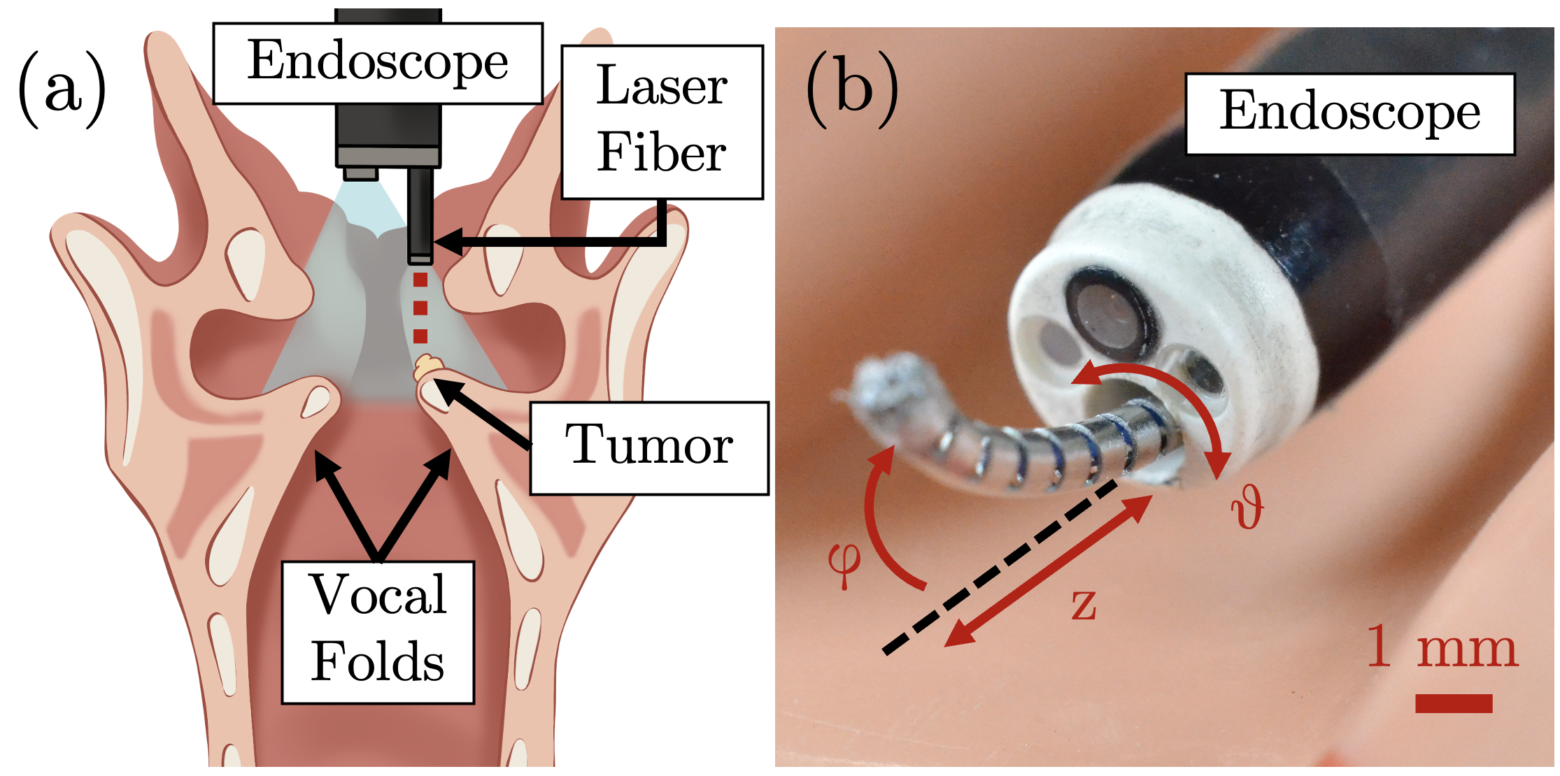
Despite its documented benefits, in-office surgery is still underutilized because of how challenging it can be to perform. One of the key limitations is the lack of articulation in the optical fibers used for laser delivery: it is only possible to control the laser aiming indirectly, i.e., bending the endoscope’s distal tip. This greatly limits anatomical access [3], and it also makes the procedure disorienting for the operating physician due to the inability to control the laser aiming without also moving the field of vision[4, 5]. Patients who present with a disease in hard-to-reach locations are not good candidates for office treatment; and even if a procedure is attempted, it can result in incomplete treatment, and therefore the need for additional follow-up care [4].
Seeking to overcome these limitations, in this paper, we describe the design, construction, and validation of a new robotic device to enable optical fiber bending during endoscopic office procedures. The device is shown in Fig. 1(b); it is built by installing an off-the-shelf optical fiber into a tendon-actuated Nickel-Titanium continuum notched sheath. The sheath diameter is 1.1 mm, which makes it suitable for trans-luminal deployment through the operating channel of most clinical endoscopes. In addition to bending, the sheath can also be rotated and translated, thus providing a total of three degrees of freedom (DoFs). Actuation is provided by a modular add-on motor unit that mounts on the endoscope handle. We report experimental evidence, obtained in simulation and phantom experiments, documenting the ability of our device to reach and deliver laser pulses to regions within the larynx that are currently inaccessible in-office procedures. This paper is the first report on a surgical robotic device specially designed to be compatible to use with a commercial endoscope for in-office laryngeal surgery.
II Background & Related Work
Several other groups are actively developing robots for laryngeal laser surgery [6, 7, 8, 9, 10, 11, 12], but none of the existing prototypes can be readily used in the office procedures we consider in this study. In the following, we briefly describe the surgical setup and workflow of an office procedure. We then illustrate the challenges that motivate our work and formulate the specifications that guided our design process.
II-A Overview of Office Procedures in the Larynx
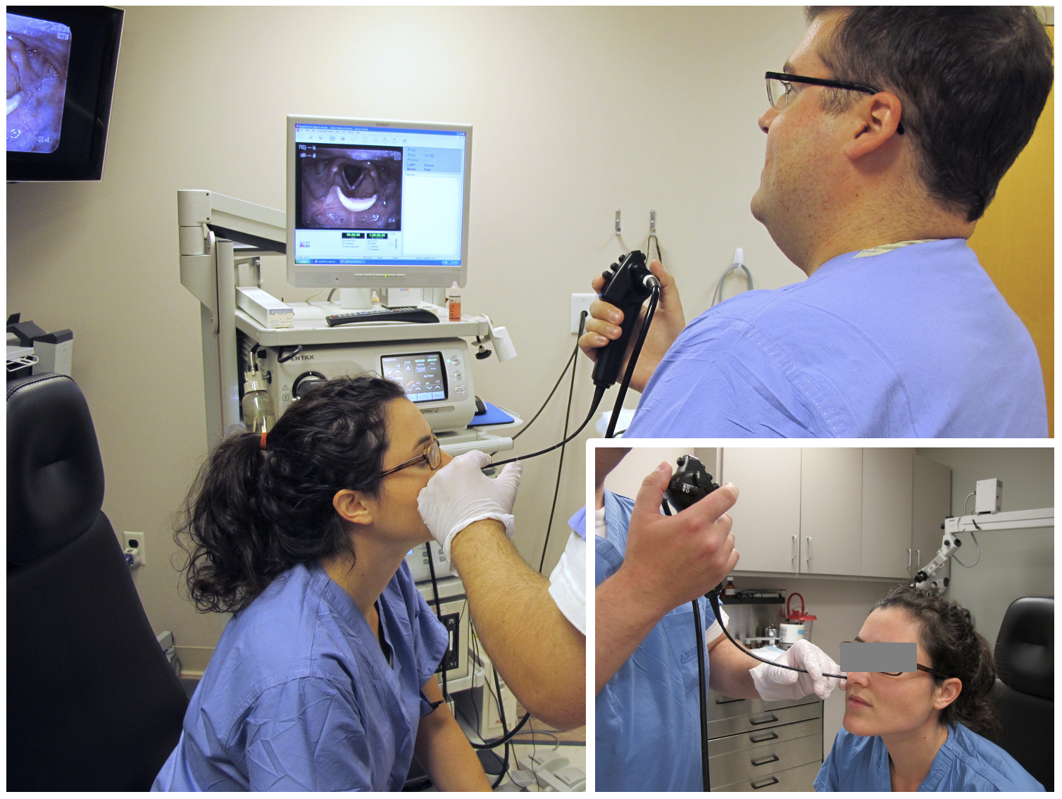
Office-based laryngeal procedures are performed as shown in Fig. 2. Patients receive the procedure awake while sitting on an examination chair. To visualize the larynx, the operating physician introduces a flexible endoscope through the nose, prior to the administration of a topical anesthetic. In principle, it would be possible to pass the endoscope through the mouth, but this approach is generally avoided as it can easily trigger the gag reflex [13]. The endoscope needs to be sufficiently small to pass through one of the nostrils, and ideally as small as possible to minimize patient discomfort. The typical endoscope diameter for these procedures is 5 mm [14, 5]. Endoscopes are equipped with a working channel, typically 2 mm in diameter, which enables the passage of optical fibers for laser delivery.
The goal of a procedure is to thermally destroy diseased tissue via the application of laser pulses. Benign tumors of the voice box (e.g., cysts and nodules) are ideal targets, as they are known to respond well to laser treatment [15]. Laser application is halted by the operating physician when visible blanching (i.e., whitening of the tissue, which signals thermal necrosis [4]) is observed; at this point, the endoscope is retracted and the procedure is concluded. It is important to note that no tissue is excised in the course of an office procedure: Necrotized tumors are left in place, where they spontaneously involute (i.e., necrotized tissue is re-absorbed and eliminated as part of the body’s own healing processes) over the course of a few weeks [14].
II-B Challenges of Office Procedures
While office procedures have been shown to be generally safe and effective, recent clinical studies revealed that there exist several hard-to-reach locations inside the larynx where laser treatment cannot be delivered [4, 5]. This issue can be attributed to the limited dexterity of clinical instruments: the laser fibers used in office procedures can only emit light forward in a line-of-sight fashion, making it hard to reach tumors that lie off the longitudinal axis of the fiber (refer to Fig. 1). Physicians can control the laser aiming by bending the distal tip of the endoscope; however, this does not provide sufficient anatomical coverage [4, 5]. In recent work, our group characterized the reachable workspace of laryngeal endoscopes and identified the regions within the larynx where access is problematic [3]. These regions include, among others, the two cavities immediately above the vocal folds and the inferior surface of the vocal folds (see Fig. 1). Patients who develop tumors in one of these areas are not suitable candidates for office surgery and have to resort to the traditional (and more expensive) surgical treatment in the operating room. Reachable workspace maps from our earlier study [3] are reproduced in this paper (sec. IV) and compared to the reachable workspace of the new steerable fiber we propose in the following.
II-C Design Specifications
To overcome the kinematic limitations of current clinical instruments, and thus amplify a physician’s reach into the larynx, in this paper we propose a robotic steering mechanism to enable the controlled bending of the optical fibers used for laser delivery. To guide the design of our device, we used the following specifications:
II-C1 Range of Motion
Based on our prior analysis of the laryngeal workspace in [3], we anticipate that a mechanism able to bend the optical fiber by at least 90° would double the extent of reachable anatomy and enable access to several challenging areas, including those immediately above and below the vocal folds mentioned earlier.
II-C2 Miniaturization
The steering mechanism should be sufficiently small to permit deployment of the fiber through the working channel of the operating endoscope. Meeting this specification is important to minimize patient discomfort: a larger mechanism would have to be deployed separately from the endoscope, either through the mouth or the other nostril. While several miniaturized laser steering mechanisms have been proposed in recent years [16, 17], none of them is sufficiently small to pass through the 2 mm lumen of a laryngeal scope.
II-C3 Ease of Integration in the Surgical Workflow
Introducing the robotic steering mechanism should not fundamentally alter the surgical setup or workflow. Ideally, physicians should be able to continue to perform the procedure using the instrumentation they are already familiar with and a setup as close as possible to the one illustrated in Fig. 2.
III System Overview
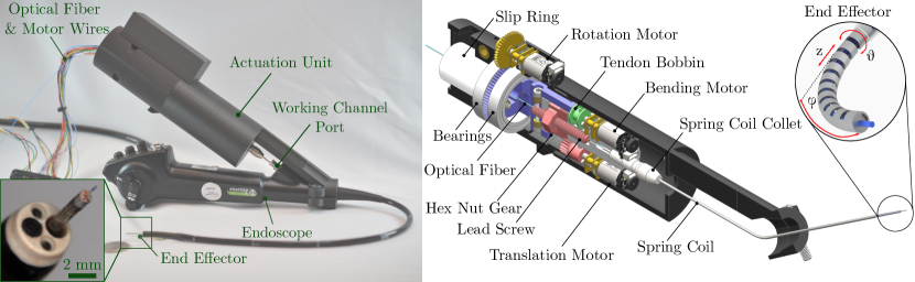
Our proposed robotic steerable fiber is shown in Fig. 3. In this section, we provide an overview of the two main components of the device, namely the end effector and its actuation unit.
III-A End Effector
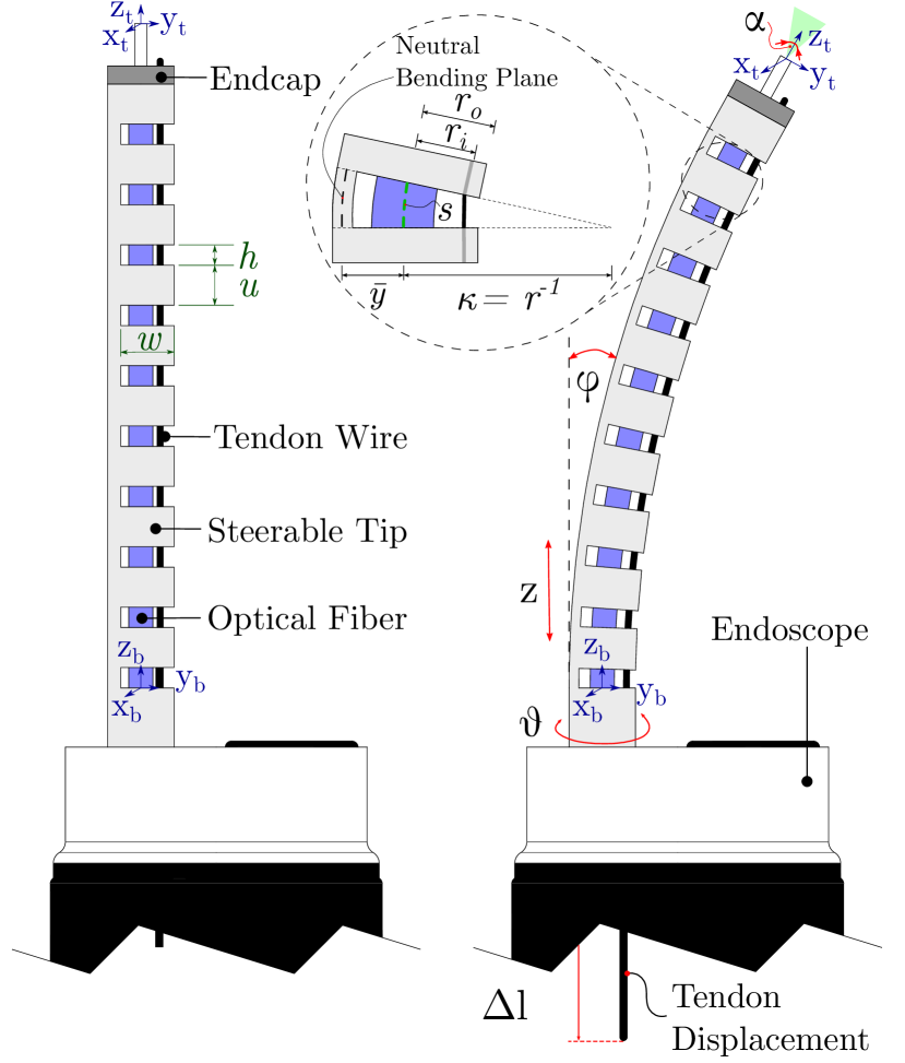
A schematic of the end effector, illustrating its components and dimensions, is shown in Fig. 4. It consists of an off-the-shelf optical fiber installed into a tendon-actuated Nickel-Titanium (Nitinol) notched continuum sheath. The optical fiber is the FP200ERT (Thorlabs, Newton, NJ, USA), a multimode fiber with a diameter of 0.225 mm, capable of withstanding bending radii as tight as 6 mm [18]. The distal end of the Nitinol sheath is outfitted with an aluminum end cap, which is installed by press-fitting. The end cap has three holes (see Fig. 3): the center one, 0.3 mm in diameter, holds the optical fiber, while the other two, 0.2 mm in diameter, are used as attachment points for the actuation tendon. Fabrication of the end cap was carried out with a Super Mini Mill CNC machine (Haas Automation, Oxnard, CA, USA).
The steerable sheath uses the asymmetric notch pattern proposed by Swaney and colleagues in [19]. Compared to other continuum mechanisms, this solution facilitates miniaturization, as bending only necessitates a single pull wire. A potential disadvantage of asymmetric notches is that they only permit unidirectional bending, though this is not a major concern as long as the sheath can also be rotated.
The notched sheath is fabricated starting from a solid Nitinol tube wherein notches are then cut with a femtosecond laser. To build our prototype, we purchased Nitinol tubing from Johnson Matthey (West Chester, PA, USA), while laser cutting was outsourced to Pulse Systems (Concord, CA, USA). Custom-sized Nitinol tubing can be expensive for initial prototyping, therefore we used the smallest tube diameter available in stock at the time of purchase that also had a sufficiently large lumen to accommodate the optical fiber. For our prototype shown in Fig. 3, we used a Nitinol tube with an outer diameter of 1.1 mm and a wall thickness of 0.1 mm. The notch dimensions are illustrated in Fig. 4 and their values are listed in Table I; these are the notch height , width , and the spacing between each pair of consecutive notches.
| Name | Symbol | Value (mm) |
|---|---|---|
| Notch Width | 0.94 | |
| Notch Spacing | 1.31 | |
| Notch Height | 0.19 |
As we shall see in the following paragraph, the notch dimensions play directly into the kinematics of the sheath; the notch dimensions listed in Table I guarantee the desired minimum fiber bending of 90°, and at the same time ensure that the bending radius of the device never goes below 6 mm, which could lead to fiber breakage. To describe the kinematics of the end effector, we use the model from [19]. This model tracks the sheath’s bending as a function of the tendon displacement (refer to Fig. 4). Briefly, the steerable sheath can be considered as an open kinematic chain composed of a sequence of interleaving cut and uncut segments. Uncut sections are assumed not to undergo any deformation; therefore, their contribution to the kinematics is a simple translation along the local axis:
| (1) |
where is the notch spacing. The operator ^ in Eq.(1) maps twists from to elements of (3), i.e. the Lie Algebra of the special Euclidean group . Evaluating the exponential on the right-hand side of the equation yields the corresponding homogeneous transformation matrix . For the notched sections, the kinematics model in [19] assumes bending in the shape of a constant curvature arc. The corresponding homogeneous transformation matrix can be expressed in terms of the arc curvature and length (shown in the inset in Fig. 4).
| (2) |
The notch arc parameters and are related to the tendon displacement , as it was shown in [19]:
| (3) |
where is the inner radius of the sheath and is the location of the neutral bending plane with respect to the center axis of the sheath. This latter quantity can be calculated using the relations in [19]. Finally, the transformation matrix between the base of the steering section and the tip of the robot (i.e., frames b and t in Fig. 4) is given by:
| (4) |
where = 10 is the total number of notches used in our design and represents an offset along the local axis that accounts for the presence of the end cap and the optical fiber at the tip of the end effector.
The maximum sheath bending angle is achieved when all the notches are closed. From simple geometry, this quantity is given by [19]:
| (5) |
By replacing the parameter values from Table I in the equation above, and calculating the neutral bending plane location using the relations in [19], it can be verified that our steerable sheath can bend up to 107.15°, thus satisfying the first of the design specifications listed earlier in sec. II. Furthermore, one can use the relations in [19] to verify that the minimum bending radius of the sheath is 6.9 mm. This ensures that the internal optical fiber (which, as noted earlier, can bend down to a radius of 6 mm) will not break due to excessive bending.
III-B Actuation Unit
The actuation unit includes three 6 volt brushed DC micro-motors (Pololu Corp., Las Vegas, NV, USA). The motors and their respective transmission units are arranged within a 3D-printed cylindrical housing, 45 mm in diameter and 165 mm in length. The unit is rigidly attached to the endoscope handle via a custom mount, so that, during a procedure, a physician could hold both the endoscope and the robot with the same hand. The weight of the actuation unit is 250 grams.
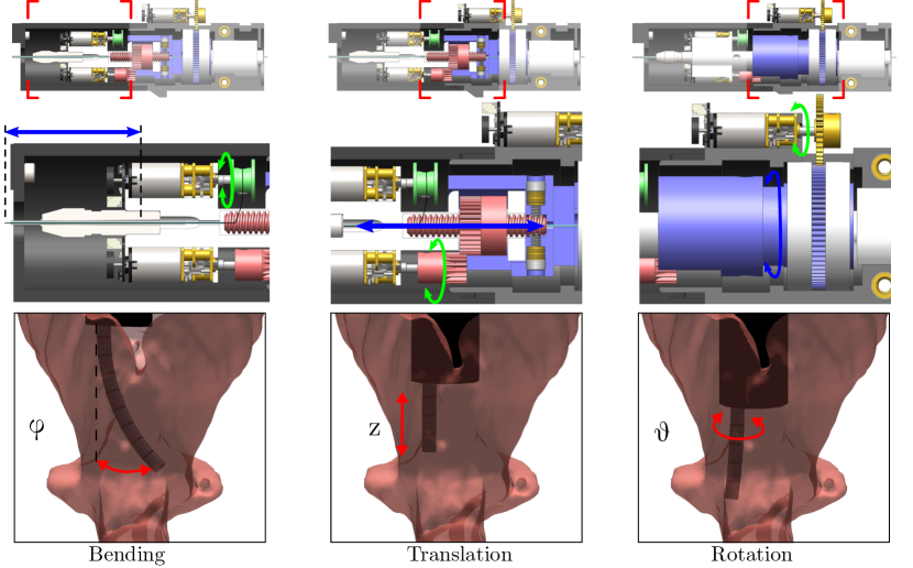
The operation of the actuation unit is illustrated in Fig. 5. Connection to the end effector uses a stainless steel spring coil, the ACT ONE Standard (Asahi Intecc, Seto, Japan), which acts as a flexible transmission shaft for rotation and translation. The hollow lumen of the spring coil is used to pass the optical fiber and the actuation tendon to the notched sheath at the end effector. The spring coil has an outer diameter of 1.37 mm and an inner diameter of 0.81 mm.
III-B1 Bending
End effector bending is created by pulling its actuation tendon. The tendon is wound up on a bobbin (shown in green in Fig. 5) which is directly attached to the shaft of one of the motors.
III-B2 Translation
Translation is created via a lead screw and nut mechanism that converts the rotary motion of another DC motor to linear translation. The lead screw is hollow to allow the insertion of the laser fiber. The encased hex nut moves linearly along the stationary lead screw, at a rate of 1.60 mm per turn. To maintain independence between bending and linear translation of the end effector, the bending transmission travels with the translation mechanism as to not affect the tension of the actuation tendon. The guiding rails built into the design act as a mechanical limit for the translation distance. The total travel distance is 17.0 mm.
III-B3 Rotation
Rotation uses a motor connected to a brass gear, which interfaces with a custom gear (shown in blue in Fig. 5). The gear ratio between the motor shaft and the spring coil collet is 7:4. To prevent twisting in the optical fiber and entangling of electrical cables, the actuation unit uses a through-hole slip ring to transmit power and signals from the static to the moving portion of the unit.
IV Reachable Workspace Characterization
This section reports the studies we performed to characterize the reachable workspace of our new steerable fiber. These studies used the same computational simulation framework we previously developed in [3]. Briefly, we first let a computer program manipulate the endoscope and the laser fiber in simulation, and perform an extensive exploration of the reachable workspace with a sampling-based motion planning algorithm. A ray casting procedure is then used to simulate the application of laser pulses from the fiber tip, as well as to simulate the field of view of the endoscope camera. The output of this process is a three-dimensional map indicating what tissue can simultaneously be reachable by the laser beam and visible by the endoscope camera within a given anatomical model.
The endoscope we simulate is the Pentax VNL-1570STK14 (same make and model shown in Fig. 3). The kinematics of this endoscope and its range of motion were previously determined experimentally by our group in [3]. The motion of the steerable wrist is simulated using the kinematics model previously described in sec. III-A.
To simulate the larynx anatomy, we use two high-resolution three-dimensional larynx models obtained from micro-tomography scans of cadavers [20]. The scans were processed with a MATLAB (The Mathworks, Natick, MA, USA) script to generate three-dimensional stereolithography (STL) models. Reachability maps are calculated via the following procedure: First, we generate 10,000 random endoscope+fiber configurations using the Rapidly-Exploring Random Trees (RRT) algorithm. From each of these reachable configurations, we run a ray casting algorithm to simulate the application of laser pulses. We generate 1,000 virtual rays from the tip of the fiber in a cone that mimics the laser beam. With each of these rays, we use the Möller-Trumbore ray-triangle Intersection algorithm to detect what faces of the STL larynx model are visible in a direct line of sight. Results are shown in Fig. 6. To evaluate the benefits of adding steering to laser fibers, we compare our results with reachable tissue maps previously calculated by our group in [3] for clinical non-steerable laser fibers (”Traditional Fiber” in Fig. 6). Our new steerable fiber was found to provide significantly more extensive access to the larynx anatomy, compared to traditional clinical fibers. Enhanced coverage is observed particularly in the area surrounding the vocal folds, which as was noted earlier, can be challenging to reach with current clinical fibers. Table II shows numerical results, indicating that being able to bend laser fibers more than doubles the amount of accessible tissue.
| Traditional Fiber | Steerable Fiber | |
|---|---|---|
| cm2 | cm2 | |
| Larynx 1 | 8.99 | 20.65 |
| Larynx 2 | 8.51 | 19.30 |
V Experiments
V-A Kinematics Verification
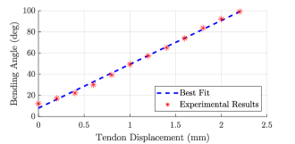
To verify that the robot can be controlled using the kinematic model [19], we performed an experiment wherein the actuation tendon was pulled in 0.2 mm increments until all the notches were observed to be fully closed. For tendon pulling, we used a manually-actuated linear slider (Velmex, Bloomfield, NY, USA), which has a resolution of 0.01 mm. After each increment, we took a photograph of the end effector with a digital single-lens reflex camera outfitted with a macro objective (Nikkor 40mmf/2.8 G, Nikon Corporation, Tokyo, Japan) and performed image processing with a custom MATLAB script to measure the bending angle . The pixel resolution of each photograph was 4928 3624, with a mm-per-pixel ratio of 0.007 mm/pixel.
The experiment was repeated five times. After each trial, we reset the position of the steerable fiber without recording the unbending motion. The average bending angle for a given amount of tendon displacement is displayed in Fig. 7. The standard deviation among the 5 trials was 1°for all values of . As can be seen in Fig. 7, there is a linear relationship between the tendon displacement and the bending angle of the steerable fiber. This result is consistent with the modeling work in [19]. By fitting a linear model, we can map the tendon displacement to the bending angle of the steerable fiber to control its position.
V-B Phantom Experiments
To verify the robot’s ability to access hard-to-reach locations inside the larynx, we performed a set of experiments using a 3D-printed phantom model of the human larynx.
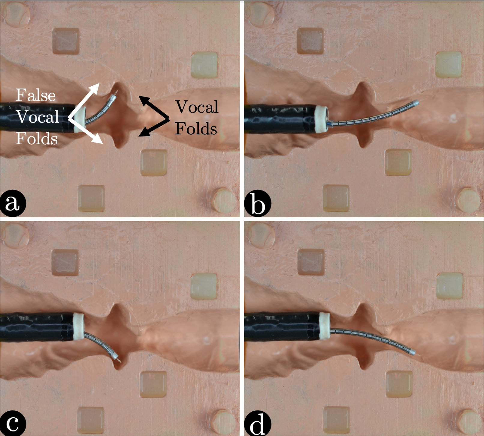
The phantom model, pictured in Fig. 8, was printed with a Form 2 printer (Formlabs, Somerville, MA, USA). This is the same anatomical model showed earlier in Fig. 6 and labeled ”Larynx 1.” The model was printed as a two-piece phantom, so that we could open it and take pictures to document the robot’s deployment (see Fig. 9).
To enable registration between the 3D-printed phantom and its STL model, we created four fiducial points, as shown in Fig. 8.

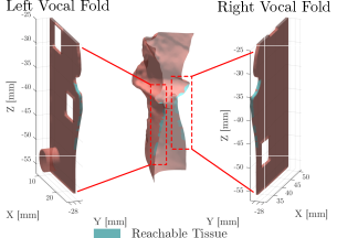
The experiments were carried out as follows: first, the endoscope was deployed into the phantom model so that the steerable fiber probe would navigate in plane with the phantom surface. With the endoscope stationary, we deployed the robotic steerable fiber into the phantom model and visually aligned it with the surface of the model. The robot was controlled using a bench-top control panel with buttons for each of the degrees of freedom described earlier in sec. III. The steerable fiber was maneuvered to follow the profile of the tissue surface, scanning from above the vocal folds to the region immediately below, as shown in Fig. 9. Throughout each experiment, we tracked the location and orientation of the end effector’s tip from images (using the same camera and lens previously used in the kinematics verification experiments), and then used the registration between the phantom and its STL model to project a virtual model of the robot in the STL space. This enabled us to use the same ray casting technique described earlier in sec. IV to identify the tissue accessed by the fiber. Results are shown in Fig. 10, and they show our robot’s ability to reach the regions immediately above and below the vocal folds, which are currently out of reach with traditional clinical fibers.
VI Discussion
Experimental results indicate that the proposed robotic steerable fiber has the potential to substantially enhance surgical access during office procedures in the larynx. There are two particularly hard-to-reach regions within the larynx, i.e., the set of cavities immediately above the vocal folds and the under-surface of the vocal folds. Our robot enables access to both of these regions, as can be seen in Figs. 6 and 9. As of today, patients who present with tumors in these locations are not eligible for office surgery and have to resort to traditional surgical treatment in the operating room. We expect that the robot we propose in this paper will help overcome these difficulties and help move surgeries out of the operating room and into the doctor’s office. In separate work [18], we developed an optical coupling system to connect our robot to a surgical laser station, and we demonstrated the ability of the system to deliver sufficient laser energy to produce heating and ablation of tissue.
One limitation of the present work is that surgical access was only demonstrated in a limited number of larynx models. Since this is an initial proof-of-principle study, inter-patient variability is not a factor that was accounted for, and it is something that we plan to investigate further in the future. Finding high-definition three-dimensional larynx models has traditionally been difficult (the larynx anatomy contains tiny structures that are not straightforward to capture with clinical medical imaging protocols); however, recent years have seen the appearance of a number of medical image sets, like the one recently posted by Bailly et al. in [20] that could be used for our purpose. In future work, we will explore methods to optimize the design of the steerable sheath to further increase anatomical coverage. More complex designs, such as those recently presented in [21, 22], may allow more comprehensive surgical access than the simple unidirectional design we describe in this paper. Further studies will be needed to translate our device to clinical practice. We designed our robot so that it could be operated by the operating physician without the need for an assistant or a supporting arm. For the purpose of this study, the robot was controlled with a bench-top control interface. While this is useful for initial verification and validation, in-office use dictates placing the user interface on the actuation unit for single-handed control of the device, so the operating physician may control the steerable fiber without disrupting the surgical workflow. A simple solution would be to integrate control buttons on the outside shell of the actuation unit, within reach of the physician’s fingers. Ultimately, we plan to conduct a study where we collect inputs from multiple physicians and study the ergonomics of different control interfaces.
VII Conclusion
This paper introduced a novel steerable laser fiber for in-office laser surgery in the voice box. We reported evidence, obtained in simulations and phantom experiments, documenting the ability of our robot to substantially enhance surgical access within the larynx. To the best of our knowledge, this paper is the first report of a surgical robot developed specifically for office procedures in the larynx. To design our robot, we explicitly took into account the surgical setup and workflow of these procedures, and propose a set of specifications that attempt to facilitate the integration of the robot in the surgical setup. Future work will focus on the development of a user interface to provide single-handed manipulation.
References
- [1] A. G. Hantzakos and M. Khan, “Office laser laryngology: A paradigm shift,” Ear, Nose & Throat Journal, vol. 100, no. 1_suppl, pp. 59S–62S, 2021.
- [2] S. Chen, J. Connors, Y. Zhang, B. Wang, D. Vieira, Y. Shapira-Galitz, D. Garber, and M. R. Amin, “Recurrent respiratory papillomatosis office versus operating room: Systematic review and meta-analysis,” Annals of Otology, Rhinology & Laryngology, vol. 130, no. 3, pp. 234–244, 2021.
- [3] I. A. Chan, J. F. d’Almeida, A. J. Chiluisa, T. L. Carroll, Y. Liu, and L. Fichera, “On the merits of using angled fiber tips in office-based laser surgery of the vocal folds,” in Medical Imaging 2021: Image-Guided Procedures, Robotic Interventions, and Modeling, vol. 11598. International Society for Optics and Photonics, 2021, p. 115981Z.
- [4] A. G. Del Signore, R. N. Shah, N. Gupta, K. W. Altman, and P. Woo, “Complications and failures of office-based endoscopic angiolytic laser surgery treatment,” Journal of Voice, vol. 30, no. 6, pp. 744–750, 2016.
- [5] H.-C. Hu, S.-Y. Lin, Y.-T. Hung, and S.-Y. Chang, “Feasibility and associated limitations of office-based laryngeal surgery using carbon dioxide lasers,” JAMA Otolaryngology–Head & Neck Surgery, vol. 143, no. 5, pp. 485–491, 2017.
- [6] A. Bajo, L. M. Dharamsi, J. L. Netterville, C. G. Garrett, and N. Simaan, “Robotic-assisted micro-surgery of the throat: The trans-nasal approach,” in 2013 IEEE International Conference on Robotics and Automation. IEEE, 2013, pp. 232–238.
- [7] A. Acemoglu, N. Deshpande, J. Lee, D. G. Caldwell, and L. S. Mattos, “The calm system: New generation computer-assisted laser microsurgery,” in 2019 19th International Conference on Advanced Robotics (ICAR). IEEE, 2019, pp. 641–646.
- [8] M. Zhao, T. J. O. Vrielink, A. A. Kogkas, M. S. Runciman, D. S. Elson, and G. P. Mylonas, “Laryngotors: A novel cable-driven parallel robotic system for transoral laser phonosurgery,” IEEE Robotics and Automation Letters, vol. 5, no. 2, pp. 1516–1523, 2020.
- [9] L. S. Mattos, A. Acemoglu, A. Geraldes, A. Laborai, A. Schoob, B. Tamadazte, B. Davies, B. Wacogne, C. Pieralli, C. Barbalata et al., “ralp and beyond: Micro-technologies and systems for robot-assisted endoscopic laser microsurgery,” Frontiers in Robotics and AI, p. 240, 2021.
- [10] R. Renevier, B. Tamadazte, K. Rabenorosoa, L. Tavernier, and N. Andreff, “Endoscopic Laser Surgery: Design, Modeling, and Control,” IEEE/ASME Transactions on Mechatronics, vol. 22, no. 1, pp. 99–106, 2 2017.
- [11] D. Kundrat, R. Graesslin, A. Schoob, D. T. Friedrich, M. O. Scheithauer, T. K. Hoffmann, T. Ortmaier, L. A. Kahrs, and P. J. Schuler, “Preclinical Performance Evaluation of a Robotic Endoscope for Non-Contact Laser Surgery,” Annals of Biomedical Engineering, pp. 1–16, 8 2020. [Online]. Available: https://doi.org/10.1007/s10439-020-02577-y
- [12] G. Fang, M. C. Chow, J. D. Ho, Z. He, K. Wang, T. Ng, J. K. Tsoi, P.-L. Chan, H.-C. Chang, D. T.-M. Chan et al., “Soft robotic manipulator for intraoperative mri-guided transoral laser microsurgery,” Science Robotics, vol. 6, no. 57, p. eabg5575, 2021.
- [13] M. Zheng, N. Arora, N. Bhatt, K. O’Dell, and M. Johns III, “Factors associated with tolerance for in-office laryngeal laser procedures,” The Laryngoscope, 2021.
- [14] K. M. Tibbetts and C. B. Simpson, “Office-based 532-nanometer pulsed potassium-titanyl-phosphate laser procedures in laryngology,” Otolaryngologic Clinics of North America, vol. 52, no. 3, pp. 537–557, 2019.
- [15] H. Shoffel-Havakuk, B. Sadoughi, L. Sulica, and M. M. Johns III, “In-office procedures for the treatment of benign vocal fold lesions in the awake patient: a contemporary review,” The Laryngoscope, vol. 129, no. 9, pp. 2131–2138, 2019.
- [16] P. A. York, R. Peña, D. Kent, and R. J. Wood, “Microrobotic laser steering for minimally invasive surgery,” Science Robotics, vol. 6, no. 50, p. eabd5476, 2021.
- [17] O. Ferhanoglu, M. Yildirim, K. Subramanian, and A. Ben-Yakar, “A 5-mm piezo-scanning fiber device for high speed ultrafast laser microsurgery,” Biomedical optics express, vol. 5, no. 7, pp. 2023–2036, 2014.
- [18] M. Zhu, Y. Shen, A. J. Chiluisa, J. Song, L. Fichera, and Y. Liu, “Optical fiber coupling system for steerable endoscopic instruments,” in 2021 43rd Annual International Conference of the IEEE Engineering in Medicine & Biology Society (EMBC). IEEE, 2021, pp. 4871–4874.
- [19] P. J. Swaney, P. A. York, H. B. Gilbert, J. Burgner-Kahrs, and R. J. Webster, “Design, fabrication, and testing of a needle-sized wrist for surgical instruments,” Journal of Medical Devices, Transactions of the ASME, vol. 11, no. 1, p. 014501, 12 2017.
- [20] L. Bailly, T. Cochereau, L. Orgeas, N. H. Bernardoni, S. R. Du Roscoat, A. Mcleer-Florin, Y. Robert, X. Laval, T. Laurencin, P. Chaffanjon et al., “3d multiscale imaging of human vocal folds using synchrotron x-ray microtomography in phase retrieval mode,” Scientific reports, vol. 8, no. 1, pp. 1–20, 2018.
- [21] D. V. A. Nguyen, C. Girerd, Q. Boyer, P. Rougeot, O. Lehmann, L. Tavernier, J. Szewczyk, and K. Rabenorosoa, “A hybrid concentric tube robot for cholesteatoma laser surgery,” IEEE Robotics and Automation Letters, vol. 7, no. 1, pp. 462–469, 2022.
- [22] N. E. Pacheco, J. B. Gafford, M. A. Atalla, R. J. Webster III, and L. Fichera, “Beyond constant curvature: A new mechanics model for unidirectional notched-tube continuum wrists,” Journal of Medical Robotics Research, vol. 6, no. 01n02, p. 2140004, 2021.