Quasiparticle Spectrum in Mesoscopic Superconducting Junctions with Weak Magnetization
Abstract
We theoretically investigate the effects of the weak magnetization on the local density of states of mesoscopic proximity structures, where two superconducting terminals are attached to a side surface of the diffusive ferromagnet wire with a phase difference. When there is no phase difference, the local density of states is significantly modified by the magnetization in both spin-singlet -wave and spin-triplet -wave cases. When the phase difference is , the local density of stets is less modified by the magnetization compared with the in-phase case because of the destructive interference of Cooper pairs.
pacs:
I Introduction
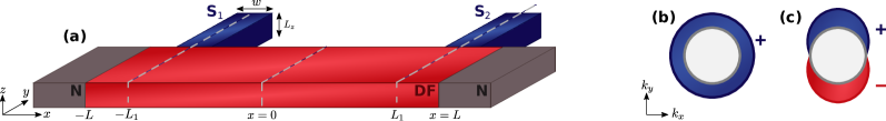
The proximity effect, the penetration of Cooper pairs, is a characteristic phenomenon observed in superconducting junctions. Cooper pairs penetrating into a non-superconducting material show superconducting-like phenomena, for example, the suppression of the local density of states (LDOS) at the Fermi level (zero energy) and the screening of magnetic fields. The penetration length of Cooper pairs is limited to with and being the diffusion constant and the temperature. Although is the characteristic length scale of the proximity effect, Volkov and Takayanagi have shown that the conductance of a two-superconductor (SC) junction [see Fig. 1(a)] depends on the phase difference between the two SCs even when the distance between two SC is much longer than VT . This effect is named the long-range phase-coherent effect.
The theory of the phase-coherence effect has been extended to spin-triplet -wave junctions Suzuki_PRB_2019 . The -wave SC is known to host Majorana bound states which is essential to realize the quantum computation. The so-called Tanaka-Nazarov boundary condition enables to study the energy spectrum of junctions with an unconventional pairing Tanaka_Nazarov . The Majorana zero-energy peak (ZEP) in the LDOS has been found to vanish when the phase difference is because of the destructive interference of Cooper pairs.
The ZEP can appear also in the junction of a diffusive weak-ferromagnetic metal (DF) and an -wave SC. The energy shift due to the magnetization can result in an accidental ZEP when is comparable to the minigap size Zareyan_PRL ; Bergeret_PRB ; Golubov_JETP ; Yokoyama_PRB_2006 . In the -wave case, the magnetization known to change the Majorana ZEP to the V-shaped LDOSYokoyama_PRB_2007 . However, we have not known how the accidental ZEP for the -wave junction and the V-shaped LDOS are modulated by the interference of Cooper pairs. The interplay between the magnetization and the phase coherence has not been elucidated yet.
In this paper, we study the LDOS in a DF wire by solving numerically the quasiclassical Usadel equation. We consider the Volkov-Takayanagi (VT) junction as shown in Fig. 1(a), where two SCs are attached to the side surface of the DF with the phase difference . The order parameter is assumed the spin-singlet -wave and triplet -wave. The magnetization is assumed with . In the -wave case, the accidental ZEP caused by is flattened when due to the destructive interference among Cooper pairs injected from different SC wires. In the -wave junction with , the LDOS is modified by from the ZEP to the V-shaped. When , on the other hand, the LDOS is less modified by because the LDOS structure is less prominent due to the destructive interference.
II System and Formulation
II.1 Usadel equation
In this paper, we consider the junctions of a DF where two superconducting (S) wires are attached to a side surface of the DF as shown in Fig. 1 [i.e., Volkov-Takayanagi (VT) junctions]. Narrow S wires with the width are attached to the DF wire at and with an interface resistance , where with . The DF is connected to clean normal-metal wires at which are sufficiently narrow and thin in the and directions (i.e., ).
The Green’s function in the DF obeys the Usadel equationUsadel :
| (1) | |||
| (4) |
where is the diffusion constant in the DF, with , and are the retarded and advanced components of the Usadel Green’s function, and is the Hamiltonian-like matrix. In this paper, the accents and means matrices in particle-hole space and spin space. The identity matrices in particle-hole and spin space are respectively denoted by and . The Pauli matrices are denoted by and with . The Usadel equation is supplemented by the so-called normalization condition: . Assuming the width of the DF is much narrower than , we can ignore the spatial variation of the Green’s function in the direction in the DF. Namely, one need to consider a one-dimensional diffusive system where the Usadel equation is reduced to
| (5) |
where the last term represents effects of the S wires and . The source term is reduced from the boundary condition in the directionVT ; Suzuki_PRB_2019 . The function is unity only beneath the S wires; . The LDOS and its deviation from the normal-state value can be obtained from the and as
| (6) | |||
| (7) |
where is the density of states per spin at the Fermi level in the normal states.
In the presence of the weak magnetization, the matrix is given by Bergeret_RMP_2005 :
| (8) |
where is magnetization of the DF which is assumed much smaller than the chemical potential Note . The factor depends on : and , where and being the energy and the depairing ratio due to inelastic scatteringsDynes01 (i.e., Dynes formulation). In this case, it is convenient to reduce the matrix into one as
| (9) | |||
| (12) |
where the symbol meaning a matrix in spin-reduced particle-hole space, the factor and is for the majority and the minority spin, respectively. Here we assumed or by which one can express in terms of . In what follows, we make explicit only when necessary. The Green’s function can be simplified by the so-called parameterizationVolkov_Physica_1993 ; Golubov_JLT_1988 ; Golubov_PRB_1997 : , where we omit the index from . The Usadel equation is reduced to
| (13) |
The Usadel equation (13) is supplemented by the boundary conditions. The boundary conditions for is given by and , whereas that for is and .
II.2 Effects of superconducting terminals
The source term in Eq. (13) represents the effect of the S armsVolkov_Physica_1993 ; Golubov_PRB_1997 . The typical boundary conditionsZaitsev_1984 are no longer available for unconventional pairings. Therefore, one must employ the so-called Tanaka-Nazarov condition Tanaka_Nazarov , an extension of the circuit theory Nazarov_PRL_1994 . The boundary condition in the direction is reduced to the source term :
| (14) | |||
| (15) |
where , and are the specific resistance of the DF and the interface resistance at the DF/S interface, , and . The angle-dependent function is the transmission coefficient of the N/N interface with the -function barrier potential , is the angle of the momentum measured from the axis, and . The angular bracket means the angle average: The functions and can be obtained from the Green’s functions in a homogeneous ballistic SC:
| (16) | |||
| (19) |
where , , , the symbol has been omitted, and . The pair potential depends on the pairing symmetry of the SC: for an -wave SC and for a -wave one, where characterizes the amplitude of the pair potential and the -vector is assumed . In this paper, the spin-orbit coupling is not taken into account for simplicityNote . The boundary condition (15) is transformed into the source term:
| (20) |
where is the dimensionless parameter. The parameters and are independent. The function is a function of because it determines , whereas determines how strong the proximity effect is.
III Numerical results
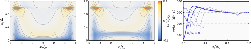
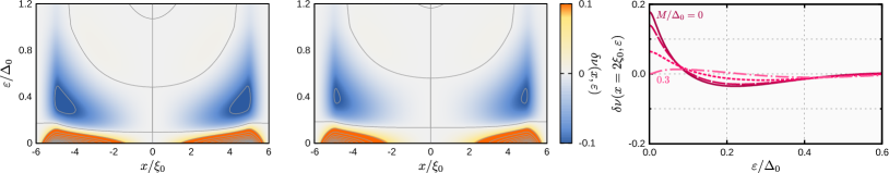
We first show the results for the spin-singlet -wave junctions in Figs. 2 and 3 where the phase difference is set to and respectively. The parameters are set to , , , and throughout this paper. Beneath the S wire, the proximity effect results in the peaks at and (i.e., the coherence peak) and the zero-energy dip. As shown in the left panel of Fig. 2, the zero-energy dip appears between the two SC terminals when and . On the other hand, the low-energy spectrum is a peak Yokoyama_PRB_2006 when as in the center panel of Fig. 2. The peak becomes higher as with increasing the distance from the SC terminal. The energy shift by , which depends on the quasiparticle spin, results in this accidental ZEP as shown in the right panel of Fig. 2, where we show at .
When , the Cooper-pair interference is destructive. Therefore the pair amplitude from each SC terminal perfectly compensate each other, leading as shown in the left and center panels of Fig. 3. Moreover, comparing Figs 2 and 3, we see that the zero-energy dip and ZEP become less prominent compared with those with . Therefore, the destructive interference is concluded to diminish the zero-energy dip and the ZEP by in the DF.
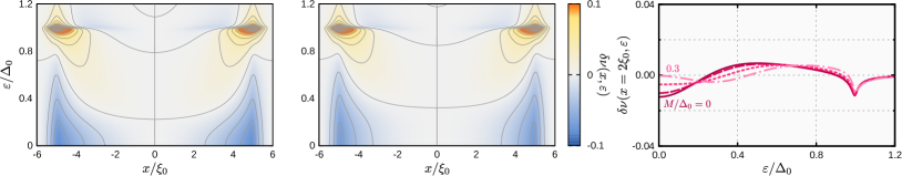
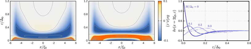
The results for the spin-triplet -wave junctions are shown in Figs. 4 and 5, where the phase difference is set to and respectively. The topologically-protected ZEP characterises the spin-triplet -wave junction as shown in the left panel of Fig. 4 RG ; SIS_Majo . This ZEP is caused by the induced odd-frequency Cooper pairs Tanaka_PRL_2007 ; Suzuki_PRB . The ZEP is robust against the weak magnetization beneath the SC wire (i.e., ) but fragile between them as shown in the center panel of Fig. 4. The LDOS deviation at is shown in the right panel of Fig. 4. The LDOS changes from the peak to the dip with increasing because of the spin-dependent energy shift. The split LDOS peak appears V-shaped at the low energy when and . In the limit, reaches to zero.
When , the ZEP around vanishes due to the deconstructive interference as discussed in Suzuki_PRB_2019 . As a result, the peak splitting becomes much less prominent as shown in the center panel of Fig. 5, where the peak height is less than 0.2. The LDOS deviation at is shown in the right panel of Fig. 5. Even when , the LDOS peak is much smaller compared with that for . The magnetization makes this LDOS peak much smaller.
IV Summary
We have investigated the effects of the weak magnetization on the LDOS of mesoscopic proximity structures, where two SC terminals with a finite phase difference are attached to the side surface of the DF.
In spin-singlet -wave junctions with , the accidental ZEP of the LDOS appears due to the energy shift by the magnetization, whereas the LDOS structures become less prominent when the phase difference is because of the destructive interference of Cooper pairs injected from different SC terminals.
In spin-triplet -wave junctions are characterised by the topologically-protected ZEP in the LDOS, corresponding to the Majorana bound state. When , the LDOS is split and becomes V-shaped at the low energy by the magnetization. On the contrary, when , the effects of the magnetization is not significant because the ZEP is much smaller even when due to the destructive interference.
Acknowledgments
This work was supported by Grants-in-Aid from JSPS for Scientific Research on Innovative Areas “Topological Materials Science” (KAKENHI Grant Numbers JP15H05851, JP15H05852, JP15H05853 and JP15K21717), Scientific Research (B) (KAKENHI Grant Number JP18H01176), Japan-RFBR Bilateral Joint Research Projects/Seminars number 19-52-50026, JSPS Core-to-Core Program (A. Advanced Research Networks). A. A. G. acknowledges supports by the European Union H2020-WIDESPREAD-05-2017-Twinning project “SPINTECH” under grant agreement Nr. 810144.
References
- (1) A. F. Volkov and H. Takayanagi, Phys. Rev. Lett. 76, 4026 (1996); A. F. Volkov and H. Takayanagi, Phys. Rev. B 56, 11184 (1997).
- (2) S.-I. Suzuki, A. A. Golubov, Y. Asano, and Y. Tanaka, Phys. Rev. B 100, 024511 (2019).
- (3) Y. Tanaka, Yu. V. Nazarov, and S. Kashiwaya, Phys. Rev. Lett. 90, 167003 (2003); Y. Tanaka, Yu. V. Nazarov, A. A. Golubov, and S. Kashiwaya, Phys. Rev. B, 69, 144519 (2004); Y. Tanaka and S. Kashiwaya, Phys. Rev. B 70, 012507 (2004). M.
- (4) M. Zareyan, W. Belzig, and Yu. V. Nazarov, Phys. Rev. Lett. 86, 308 (2001); Phys. Rev. B 65, 184505 (2002).
- (5) F. S. Bergeret, A. F. Volkov, and K. B. Efetov, Phys. Rev. B 65, 134505 (2002).
- (6) A. A. Golubov, M. Yu. Kupriyanov, and Ya. V. Fominov, JETP Lett. 75, 223 (2002).
- (7) T. Yokoyama, Y. Tanaka, and A. A. Golubov, Phys. Rev. B 73, 094501 (2006).
- (8) T. Yokoyama, Y. Tanaka, and A. A. Golubov, Phys. Rev. B 75, 134510 (2007).
- (9) K. D. Usadel, Phys. Rev. Lett. 25, 507 (1970).
- (10) F. S. Bergeret, A. F. Volkov, and K. B. Efetov, Rev. Mod. Phys. 77, 1321 (2005).
- (11) Although odd-parity superconductivity is often found in -electron systems such as uranium compounds where the spin-orbit coupling (SOC) plays roles, we ignore the effects of SOC for simplicity. Therefore, in this paper, the magnetization is assumed to interact simply with electron spin.
- (12) R. C. Dynes, V. Narayanamurti, and J. P. Garno, Phys. Rev. Lett. 41, 1509 (1978); A. A. Mikhailovsky, S. V. Shulga, A. E. Karakozov, O. V. Dolgov, and E. G. Maksimov, Solid state commun. 80, 511 (1991).
- (13) A. F. Volkov, A. V. Zaitsev, and T. M. Klapwijk, Physica C: Superconductivity 210, 21 (1993).
- (14) A. A. Golubov and M. Yu. Kupriyanov, Journal of low temperature physics, 70, 83 (1988).
- (15) A. A. Golubov, F. K. Wilhelm, and A. D. Zaikin, Phys. Rev. B 55, 1123 (1997).
- (16) A. V. Zaitsev, Zh. Èksp. Teor. Fiz. 86, 1742 (1984) [Sov. Phys. JETP 59, 1015 (1984)]; M. Yu. Kuprianov and V. F. Lukichev, Zh. Èksp. Teor. Fiz. 94, 139 (1988) [Sov. Phys. JETP, 67, 1163 (1988).
- (17) Yu. V. Nazarov, Phys. Rev. Lett. 73, 1420 (1994); Yu. V. Nazarov, Superlattices and microstructures, 25, 1221 (1999).
- (18) N. Read and D. Green, Phys. Rev. B 61, 10267 (2000).
- (19) S.-I. Suzuki, Y. Kawaguchi, and Y. Tanaka, Phys. Rev. B 97, 144516 (2018).
- (20) Y. Tanaka and A. A. Golubov, Phys. Rev. Lett. 98 037003 (2007); Y. Tanaka, Y. Tanuma, and A. A. Golubov, Phys. Rev. B 76, 054522 (2007); Y. Tanaka, M. Sato, and N. Nagaosa, J. Phys. Soc. Jpn. 81, 011013 (2012).
- (21) S.-I. Suzuki and Y. Asano, Phys. Rev. B 89, 184508 (2014); ibid., 91, 214510 (2015); ibid., 94, 155302 (2016).