Long-Range ICN for the IoT:
Exploring a LoRa System Design
Abstract
This paper presents LoRa-ICN, a comprehensive IoT networking system based on a common long-range communication layer (LoRa) combined with Information-Centric Networking (ICN) principles. We have replaced the LoRaWAN MAC layer with an IEEE 802.15.4 Deterministic and Synchronous Multi-Channel Extension (DSME). This multifaceted MAC layer allows for different mappings of ICN message semantics, which we explore to enable new LoRa scenarios.
We designed LoRa-ICN from the ground-up to improve reliability and to reduce dependency on centralized components in LoRa IoT scenarios. We have implemented a feature-complete prototype in a common network simulator to validate our approach. Our results show design trade-offs of different mapping alternatives in terms of robustness and efficiency.
Index Terms:
Wireless, decentralized Internet, LPWAN, LoRa MAC, ICN, edge communication5pt
{textblock}1(.1,0.02)
If you cite this paper, please use the IFIP Networking reference:
P. Kietzmann, J. Alamos, D. Kutscher, T. C. Schmidt, M. Wählisch.
Long-Range ICN for the IoT: Exploring a LoRa System Design.
Proc. of 21th IFIP Networking Conference, IEEE, 2022.
I Introduction
LoRaWAN is a popular low-power long-range communication system for IoT that is suitable for single-site deployments as well as for larger networks. It consists of LoRa, a PHY layer that allows for radio communication between 2 and 14 km, and higher-layer protocols mainly to upload IoT data to a server-based infrastructure. These characteristics make LoRaWAN a promising option for many urban and rural IoT scenarios.
The LoRaWAN network design incurs, however, four notable shortcomings: (i) LoRaWAN is heavily optimized towards retrieving data from constrained Nodes. Sending data to Nodes is expensive and involves significant latencies. Many networks such as the popular community The Things Network (TTN) thus deprecate sending data to Nodes above a very low message rate, making LoRaWAN unsuitable for most control scenarios. (ii) LoRaWAN has not been designed with the objective to provide a platform for Internet protocols. It is possible to use IP and adaptation layers on top of LoRaWAN, albeit very inefficiently. (iii) The whole LoRaWAN system is a vertically integrated stack that leads to inflexible system designs and inefficiencies. For example, all communication is channeled through LoRaWAN Gateways as well as Application- and Network Servers that interconnect with applications. (iv) The centralization and lock-in into vertical protocol stacks challenge data sharing (between users) and the creation of distributed applications (across LoRa island and the Internet).
In this paper, we aim for a better integration of the LoRa-based Internet of Things into the remaining Internet. We base our system design on the following four requirements: (i) enabling LoRa networks and Nodes in these networks to communicate directly with hosts on the Internet; (ii) empowering LoRa Gateways to act as routers, without the need to employ Network Servers and to tunnel all traffic to or from them; (iii) enabling secure data sharing and wireless Node control; (iv) maintaining the important power conservation and robustness properties of current LoRaWAN systems.
To achieve these goals without abandoning the benefits of the LoRA PHY (i.e., a robust, energy-efficient long-range communication channel) we propose both a complete redesign of the MAC layer and a data-driven layer on top. Our proposal leverages two key building blocks. First, the Deterministic and Synchronous Multi-Channel Extension (DSME) extension to IEEE 802.15.4e [IEEE-802.15.4-16], a flexible MAC layer that consists of contention-access and contention-free periods, and, second, the Information-Centric Networking (ICN) protocol NDN [zabjc-ndn-14], which provides secure access to named data in networks.
Prior work showed that ICN provides clear benefits over traditional IP and CoAP or MQTT stacks in the IoT [gklp-ncmcm-18], its integration into LoRa is missing, yet. We argue that ICN is well-suited for use with LoRa because its hop-wise data replication increases robustness and flexibility while reducing retransmission load. This enhances adaptivity and decreases communication overhead, whereas link capacity is scarce with LoRa. Named and authenticated data access enables location-independence since applications can access named data directly, without resorting to lower-layer addresses. Furthermore, built-in caches in ICN facilitate more efficient LoRa networks. Requests that are satisfied by an in-network cache (i) reduce link utilization, to improve on air time and wireless interference, (ii) facilitate Node sleep, and (iii) reduce long round trips introduced by slow transmissions.
In summary, our main contributions are:
- 1.
-
2.
A complete simulation environment in OMNeT++ that combines ccnSim as an ICN stack, openDSME as a MAC layer, and FLoRa to simulate LoRa-type devices—and a demonstration of our adaptation layers in that system. (§ V)
- 3.
II Background and Challenges
LoRa PHY: Long-range but very low data rates
The LoRa PHY layer defines a chirp spread spectrum modulation which enables a long transmission range (theoretical 2–14 km) using minimal energy. Spreading factor (SF), code rate, and bandwidth can be configured and directly affect the time on air and data rate. As an example, a 50 Bytes frame has an on-air time of 2.3 seconds using SF12, code rate 4/5, 125 kHz bandwidth which leads to a PHY bit rate of 250 bit/s. Varying center-frequencies in the sub-GHz ISM band constrain the duty cycle to 0.1–10 % and further limit the effective throughput. As a consequence, the maximum effective bitrate of the physical layer can be as low as 0.25 bit/s.
While the LoRa PHY provides attractive features, it clearly imposes significant constraints with respect to worst-case latency and throughput, regardless of higher layer protocols such as the MAC layer. It is important to note that LoRa networks are therefore not comparable to IEEE 802.11—instead they provide properties that incur significant challenges to higher-layer protocol design with respect to delay tolerance.
LoRaWAN MAC Layer: Limited communication models
The LoRaWAN MAC layer defines three operation modes: classes A–C. In class A, constrained Nodes send uplink using the ALOHA medium access protocol and can receive downlink traffic within two subsequent slots. This approach has three limitations: (i) ALOHA is susceptible to collisions. (ii) Downlink traffic is fairly limited and cannot be initiated by a Gateway. (iii) It prevents broadcast traffic. Class C works similarly to class A but leaves the radio always on, which enables Gateway initiated (multicast) downlink traffic but comes at high energy cost on constrained Nodes. Class B adds periodic slots which allows for “predictable” downlinks at medium energy consumption. Gateways send beacons every 128 seconds (time-synchronized by GPS). Consequently, hardware requirements are not compatible with current deployments that mostly serve class A. Beacons of neighbored Gateways can collide, for the absence of beacon synchronization. The Network Server arranges MAC schedules, however, downlink slots can overlap or be suspended. Scalability issues of class B have been analyzed in [sak-lcbmc-20]. Furthermore, uplink traffic still uses ALOHA in class B mode, which interferes with downlink traffic, so that communication is still best effort.
LoRaWAN Network Architecture: Gateway and server centric
In the LoRaWAN architecture, radio networks are connected by Gateways to a Network Server that provides over-the-air activation, message deduplication, message routing, adaptive rate control at end devices, and acknowledging messages. Gateways are merely relays that implement timing-relevant aspects of the MAC protocol such as sending beacons. In the upstream direction, Gateways forward (tunnel) frames to the Network Server over the Internet. In the downstream direction, the Network Server sends LoRaWAN messages to LoRa Nodes, which includes Gateways selection.
The LoRaWAN specification does not mandate particular deployment options, and Network Servers could in theory be co-located to Gateways. In practice, e.g., in public networks, such as TTN [ttn], Network Servers are operated in the Internet, and Gateways are peripherals of the Network Server, i.e., they cannot operate without it. While this design decision is practical with respect to ease Gateway operation, it leads to a centralized architecture around the Network Server and additional servers such as Application Servers that provide interfacing to business logic, interconnecting local LoRa networks, and data sharing.
DSME: Reliable and ICN-friendly MAC layer
The 802.15.4 DSME MAC (see [IEEE-802.15.4-16] for further details) enables new LoRa scenarios. A coordinator starts network formation and emits beacons in a pre-defined beacon interval (including beacon collision resolution mechanisms), to initiate a synchronized multi superframe structure. A superframe in the multi superframe consists of: Beacon period (BP), contention-access period (CAP), and contention-free period (CFP); the latter of which provides seven guaranteed time slots (GTS), multiplexed across 16 radio channels. Data is transmitted during the CAP, a pre-allocated slot in the CFP, or in an “overloaded” beacon. Battery-driven Nodes mostly sleep (e.g., during the CAP), which makes them unavailable for the coordinator. DSME provides Indirect Transmission, in which a coordinator indicates pending transactions with a beacon. This triggers the constrained Node to stay awake after the BP.
III Design Goals
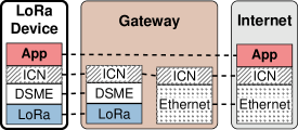
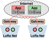
In LoRa-ICN, we are re-imagining the system architecture of long-range IoT communications, aiming to overcome the challenges described in the previous section. In our deployment scenarios, an application consists of the control and data consumer applications in the Internet and a set of LoRa-ICN Nodes (ICN producers and consumers), potentially distributed over multiple individual LoRa radio networks. Each LoRa network is served by one Gateway. The controlling and consuming applications can access all their associated wireless Nodes directly over the Internet, without mediation through application layer Gateways, see Figure 1.
Our design goals are (i) not requiring changes to the rest of the ICN network, (ii) providing a complete set of interaction patterns such as data transmission and Node control, (iii) leveraging the LoRa PHY capabilities optimally. To implement a fully distributed system model, LoRa-ICN Gateways operate as layer 3 routers instead of just bridges as in LoRaWAN. Key functions that are typically implemented by LoRaWAN Network Servers (e.g., routing) are performed by Gateways.
In order to leverage the LoRa PHY capabilities and to support the rich ICN interaction patterns, we replace the LoRaWAN MAC layer with the significantly more powerful IEEE 802.15.4 DSME MAC layer [IEEE-802.15.4-16] that provides better reliability (important for ICN Interests) and reduced latency (important for ICN consumer-publisher communication). In the following, we discuss the most relevant operations that support our deployment scenarios.
Node Registration refers to a Node registering its prefixes with the local Gateway (acting as ICN forwarders), which will install FIB entries and announce the prefixes outside the LoRa network so that Nodes do not need to participate in routing.
Data Provisioning by Nodes on LoRa Nodes includes asynchronously produced sensor data as well as requested data transmission. ICN is a receiver-driven system, so we distinguish two main variants: (i) ICN-idiomatic Interest/Data. (ii) Push Data from Nodes to Gateways. While unsolicited push is not an ICN-idiomatic communication pattern, it is still a useful capability in a resource-constrained environment because IoT Nodes may need to save energy and produce data only occasionally.
Node Control refers to Nodes being reliably controlled by peers in the Internet, e.g., for sensor control and configuration. We use a basic Interest-triggered interaction, and Data as ACK.
Data Retrieval by Nodes is natively enabled as LoRa-ICN Nodes are regular ICN Nodes and may also send Interests to other ICN Nodes hosted by the same LoRa network, other LoRa networks, or any other ICN network.
Downstream Multicast enables large-scale data distribution as needed for example in firmware updates. ICN features multicast via Node-generated Interests and broadcast Data messages from the Gateway.
IV ICN over LoRa
The LoRa PHY exhibits long on-air times (seconds) for transmit long- range (kilometers) at minimum energy consumption (micro-joules) and underlies rigorous duty-cycle restrictions. In order to achieve a robust system design, we proceed in two steps. First, we utilize a proven LoRa PHY configuration to leverage the DSME MAC. Next, we derive a viable mapping of ICN to DSME/LoRa for sending ICN Interest and Data messages from and to LoRa Nodes.
IV-A Mapping DSME to LoRa
We apply the PHY mapping presented by Alamos et al. [aksw-dfml-21] to utilize LoRa below DSME. This includes a spreading factor of 7, a bandwidth of 125 kHz, and a code rate of 4/5. The beacon interval is 125.82 s to align with LoRaWAN class B beacons (128 s). The contention-free period (CFP) defines 16 channels with a 1 % duty-cycle restriction. Beacons and CAP use a common channel of 10 % duty cycle. During CAP, Nodes perform CSMA-CA and incorporate channel activity detection (CAD) of common LoRa devices.
The CFP channels are designed to carry data of high reliability and limited latency demands. The time division of DSME, though, requires a packet queue and hence affects transmission speed. Traffic load determines queue occupation. We want to estimate the average waiting time (i.e., time in queue) for a packet that should be transmitted reliably during the CFP.
Little’s law [l-pqf-61] approximates the average waiting time , using the average number of items (i.e., queued packets) at a given average arrival rate (packet rate). We assume (i) independent, exponentially distributed inter arrival times of packets with an expectation rate of . (ii) Nodes allocate only one transmission slot in CFP and (without loss of generality) (iii) the MAC queue has infinite capacity.
Let be the number of queued packets after the transmission time of the n-th multi superframe. We note that is an ergodic Markov process (positive recurrent and aperiodic), for which the limiting distribution exists (with the number queued packets). This stationary eigenvector can be calculated numerically as a fixed point of a (clipped) high-dimensional transition matrix and yields the stationary mean occupancy prior to starting the new superframe. The actual queue that an arriving packet faces holds also packets which arrived during the current multi superframe (of duration ), i.e.,
| (1) |
As an example, we choose a relaxed packet arrival rate s and compose our multi-frame structure of superframes, i.e., ṡ. This results in an average number of queued packets and an average waiting time of s respectively. This scenario is compatible to the downlink in a common class B configuration, which exhibits an average waiting time of s but suffers from 26% loss [ekbb-elcbe-20]. In contrast, loss is very unlikely in our CFP time division period.
IV-B A MAC for ICN using a LoRa-Proxy
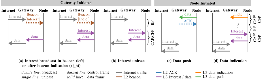
Figure 2 presents options to handle Interest and Data packets between a high throughput network (e.g., the Internet) and a DSME/LoRa network. The left part (Figure 2(a)-(b)) shows Gateway-initiated request-response communication, resembling native ICN primitives. In addition, we present protocol extensions for Nodes to initiate traffic (Figure 2(c)-(d)) to Gateways that act as proxies for constrained Nodes during sleep time.
LoRaInternet. Broadcast
Beacons are regularly broadcast by Gateways and can carry Interests without message overhead. This maximizes sleep cycles, but the limited beacon intervals reduce throughput. Using beacons to transfer Interests provides two options (see Fig. 2(a)). (i) beacons carry payloads up to a frame size of 127 Byte minus metadata, i.e., 100 Bytes/frame. Using ICNLoWPAN encoding [gksw-innlp-19] this is sufficient to aggregate 4–6 Interest packets. (ii) Gateways utilize indirect transmission (see section II) to broadcast an Interest, which involves the indication of a pending transaction within the beacon, and subsequent Interest broadcast during the CAP.
LoRaInternet. Unicast
Interest and Data messages can be sent via unicast within the CAP or CFP (see Fig. 2(b)). Sending Interests in best effort CAP frames enables requests at higher rates than in beacons. Nevertheless, this prevents Nodes from sleeping during the CAP. Note that individual Interests increase the number of downlink packets from the Gateway; for growing wireless networks this conflicts with duty cycle restrictions at the Gateway. Using the CAP for Data instead is less critical since transmissions are initiated in the low-power Node. The CFP provides exclusive resource access but adds the overhead of a preceding cell negotiation, and is limited within the superframe structure. Hence, a full CFP Interest-Data exchange requires two cell allocations per Gateway-Node pair.
LoRaInternet. Data indication
Nodes can offload the Gateway by removing the need for polling. This is done indicating names for subsequent Interests from the Gateway (see Fig. 2(d)). The indication packet, however, adds wireless traffic. Since Nodes do not emit beacons, indication packets utilize unicast traffic in the CAP or CFP. Interest and Data packets follow as outlined in Figs. 2(a) or (b). Hence, an indication and the following Interest broadcast must wait for the next beacon period. Instead, Interest unicast in CAP or CFP keeps the latency for producer-initiated traffic minimal.
LoRaInternet. Local Data push
A link-local Data push from producers to the Gateway reduces radio access and maximizes device sleep times, similar to LoRaWAN class A deployments (see Fig. 2(c)). An optional link layer ACK with retransmissions from the Node increases reliability in the CAP; the exclusive CFP slots can omit the ACK.
InternetLoRa. Unicast
Nodes request data from a Gateway by sending Interests within CAP or CFP frames (Figure 3 (a)). Data returns in a CFP cell pre-allocated for every consumer Node. This provides high reliability but becomes challenging in larger networks, since the amount of downlink cells is limited by the multi superframe.
InternetLoRa. Broadcast
Multiple Interests for the same content item arrive at the Gateway that responds with a Data broadcast message (see Figure 3(b)) using an overloaded beacon. This can help with observing duty cycle restrictions on the Gateway; however the data throughput is limited by the beacon interval.
V Simulation Environment
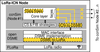
We have developed a simulation environment for LoRa-ICN that is based on OMNeT++ and the INET framework [inet-framework-21]. We integrated ccnSim [crr-chscs-13] for core ICN support and openDSME [kkt-rwmnd-18] for 802.15.4 DSME functionality. Our model uses FLoRa [spd-aclnd-18] and its wireless propagation model and PHY. Figure 4 depicts the simulation environment and our extensions.
Data flows orchestrate ICN Interest/Data exchanges and are adjusted to match IoT use cases as follows: We changed the build-in content popularity model from Mandelbrodt-Zipf to a uniform distribution and initiate one transmission for every content item. We also extended the ccnSim core implementation by two network layer primitives: (i) Indication (see subsection IV-B) and (ii) Push to place a data item in the neighboring content store. In all scenarios, content rates follow a Poisson process.
ICN-to-DSME addresses three main challenges. (i) ccnSim lacks the concept of a link layer. Instead, ICN faces directly connect to I/Os of neighboring Nodes. We include a wireless transmission link. (ii) We add a face-to-MAC module that multiplexes ICN faces to a WirelessInterface and uses MAC addresses for transmission. This module includes all logic for the ICN-to-DSME mapping (see subsection IV-B). (iii) OMNeT++ messages are converted into INET packets that map to openDSME. This step includes tagging of packets and appends control instructions for the MAC layer.
DSME-to-LoRa integrates the LoRa PHY with the DSME MAC implementation. This component bases on related work and we refer the reader to Alamos et al. [aksw-dfml-21]. We further disable dynamic slot allocation for the CFP to exclude negotiation overhead, but implement static scheduling and MAC configurations. In bidirectional communications, each Tx slot is followed by an Rx slot which halves the number of transactions in one multi superframe. Every simulation Node is assigned zero, one, or two slots depending on the MAC mapping. This pattern repeats with a multi superframe – with adjustable structure to simulate different network sizes.
VI Evaluation
We have implemented and tested different options for ICN-to-DSME mappings for the two major use cases Data from Node to Gateway and Data from Gateway to Node.
VI-A Data from Node to Gateway
Mapping Scheme Indication Interest Data Avg. Latency s Max. Latency s Data Loss % Gateway Initiated Interest broadcast Beacon CAP (Not operable at this scale) Beacon CFP Interest unicast1 CAP CAP 8.32 56.56 5.16 CAP CFP 11.67 26.87 0.05 Interest unicast CFP CAP 12.73 28.27 1.72 CFP CFP 17.01 47.24 0.00 Node Initiated Data indication CAP CFP CAP 19.25 75.17 3.13 CAP CFP CFP 14.61 71.61 1.51 CFP CFP CAP 71.62 299.22 2.6 CFP CFP CFP 46.49 241.96 0.89 Data push CAP 7.02 29.88 1.62 CFP 10.63 66.42 0.00 1Nodes must be turned on during CAP, which prevents low-power.
Motivation: Table I presents an overview of the performance for ICN/DSME/LoRa in a network of 14 Nodes, when the Node is a producer, and data flows towards the Gateway. For Gateway-initiated traffic, Interest broadcast reflects a special case which is heavily limited by the beacon interval. With an aggregation of multiple Interests into one broadcast message, the Gateway is able to send 5 Interests encoded in one broadcast packet, every 126 s (beacon interval). Consequently, we can accommodate up to 5 Nodes responding with one Data message each in the same multi superframe.
For the other mappings (see subsection IV-B) in Table I, each of the 14 Nodes produces a content item in one minute intervals (on average), and we disable Interest retransmissions to evaluate the plain ICN performance over LoRa. Interest unicast is separated into Interest-CAP and CFP variants (Interest-CAP prevents Nodes from sleep and is not feasible for battery powered devices). Interest-CAP provides short completion times of 8–12 s on average, due to frequent CAP intervals. Interest-CFP is slower by a factor of 1.5. However, sending data in the CAP increases the probability for data loss, which is most notable when Interest and Data messages share the CAP. The maximum latency increases up to 56 s as a consequence of CSMA retries. Conversely, sending Data messages in the CFP improves reliability at moderate overhead for the maximum latencies, despite less frequently available GTS for sending.
For Node-initiated traffic, we compare Data indication (a dedicated indication messages is triggering an Interest by the consumer) and Data push. In the indication case, we only consider energy-efficient options in which the Gateway uses the CFP for Interests. Our results clearly show an overhead for the three-way handshake with Data indications. Maximum latencies increase to over 70 s using the CAP for indication, and to over 240 s using the CFP, even in this unstressed scenario. Hence, we ignore Data indication for the remainder of our evaluation. In contrast, Data push can obviously be completed in a single message transmission and reduces the average completion time to 7–11 s, depending on the CAP/CFP mapping variant. Sending Data in the CAP is affected by collisions and CSMA retries. Sending Data in the CFP surprisingly reveals a maximum latency of over 60 s. We ascribe this to the randomized content creation interval that leads to occasional synchronized medium access of several Nodes and then consequently to MAC layer queue processing delays that last for multiple multi superframes (here 2) with static slot assignment.
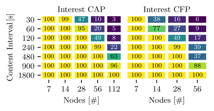
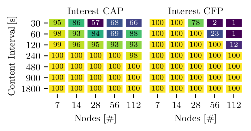
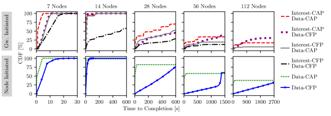
Figure 5 presents completion times for Data retrieval from LoRa Nodes in a high data rate scenario (30 s Data production intervals, 5a) and a more relaxed scenario (900 s Data production intervals, 5b) including ICN retransmissions. Data losses result in infinite completion times, hence, the end value of each graph also reflects its success ratio.
Performance at high data rates: The Gateway-initiated requests finish in less than 20 s, in a small network of 7 Nodes. The performance degrades with increasing networks. In the 14 Nodes case, 90 % of the requests are satisfied in less than 30 s except for the fully CFP-based mapping. Missing Data triggers an Interest retransmission (step at 126 s) which reflects our retransmission timeout that aligns with the beacon interval. The Interest-CFP/Data-CFP mapping, however, finishes after 600 s with 50 % loss, which is the effect of MAC queue utilization that has a service rate at the order of one superframe (). Network sizes 28 increase the completion time to the order of hundreds and thousands of seconds at high loss rates, which then becomes unusable for ICN communication.
Operating in a full CAP mapping exhibits the highest ratio of transactions successful at the first attempt but it inhibits Nodes sleeping. Furthermore, 112 Node networks reduce the delivery rate to 25 % due to collisions and denied channel access. Conversely, Interest-CAP/Data-CFP efficiently combines the “reactive” contention-based access for Interests with reliable contention-free media access for Data. Interest-CFP/Data-CFP with 112 Nodes is not possible with our current CFP scheduling approach (see Section V).
Node-initiated Data push reveals faster completion and higher reliability in comparison to the request-based pattern. Networks 28 Nodes show similar behavior for Data-CAP and -CFP transmissions. Conversely, networks 28 show the effect of MAC over-utilization for Data-CFP. The multi superframe period increases with the number of Nodes, hence, the average service rate of the MAC decreases. CAP reduction [IEEE-802.15.4-16] can mitigate this effect and will be evaluated in future work. In contrast to Data-CFP, Data-CAP performs comparably smooth and transmits 50 % of the messages within 30 s even under these stressful conditions.
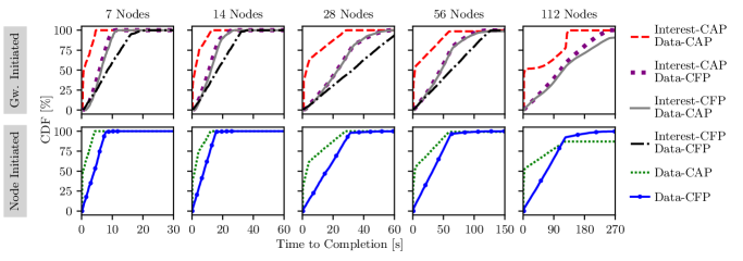
Performance at low rate: In the relaxed scenario (Figure 5b), Gateway-initiated requests perform mostly reliable for all mappings and complete with 100 % success after less than 126 s in networks 112 (note the change of the x-axis scale in comparison to Figure 5a). For 112 Node networks, Interest-CAP/Data-CAP clearly shows the effect of CSMA retries.
For Node-initiated traffic, Data-CFP is now on-par with Data-CAP and exhibits the best performance due to the contention-free media access. In the 112 Node network, the unidirectional push with Data-CAP faces collisions that cannot be compensated due to the absence of Interest retransmissions (in contrast to the Gateway-initiated case). Consequently, Data-CFP is the better option for large networks.
VI-B Data from Gateway to Node
Data unicast: Figure 6a depicts success rates for Nodes sending Interests to the Gateway with Interest-CAP and Interest-CFP mappings. Latencies are less crucial in this case since Nodes are aware of the constrained regime and sleep during long round trips. A retransmission will likely be answered by the Gateway if the requested Data has arrived in the meantime. Here, we apply Data-CFP to enable maximum sleep times. Interests are sent in the CAP or CFP and experience similar challenges as described in Section VI-A. Again, fully CFP-based mappings are not available for 112 Node networks with the current scheduler.
Figure 6a clearly shows the network operation boundaries by a diagonal in the heatmap at 30 s/28 Nodes–240 s/112 Nodes for Interest-CAP, and 30 s/14 Nodes–120 s/240 Nodes for Interest-CFP. In relaxed scenarios, both options perform similarly well. Surprisingly, Interest-CAP outperforms the reliable CFP alternative for larger networks, despite its best-effort limitation. Hence, Interest scheduling in a GTS is more susceptible to losses than concurrent channel access, however, there is a crucial caveat that our measurements cannot exhibit: In a deployment with multiple Gateways (in reach), other stub networks share the CAP which increases the collision probability. In contrast, CFP slots follow a channel hopping scheme to avoid interfering Nodes. Furthermore, neighboring LoRa networks can assign the same GTS on orthogonal channels, which increases the overall throughput. We will focus on multi Gateway scenarios in future work.
Data broadcast: Figure 6b depicts success rates for Interests in CAP or CFP and subsequent Data broadcasts with indirect transmission, triggered by the beacon sent by the Gateway. Similarly to Interest broadcast (see Section VI-A), the maximum throughput of broadcast Data packets is limited by the beacon interval. In contrast, however, Data broadcast can satisfy many pending Interests that have been aggregated during the beacon period with a single downlink packet. Applying the ICNLoWPAN encoding, our approach concatenates up to six data items into one packet. This requires a fixed Interest window size for all Nodes within one beacon interval and homogeneous content requests during this period.
Figure 6b depicts that the best broadcast performance can be achieved without Interest retransmissions with request intervals at the order of 120 s or greater, which is in line with the beacon period. The impact of the network size is less significant in comparison to Figure 6a, which emphasizes the advantage of Data broadcast. Success rates for short request intervals 120 s exhibit the advantage of Interest-CFP over CAP. Exclusive uplink resources are less susceptible to interference, whereas the shared media access during CAP suffers from limited media access and collisions.
Interest retransmissions worsen the success rate for networks 56 Nodes in this scenario, for two reasons: (i) delayed request of “old” Data occupies the limited downlink resources of the Gateway, whereas neighbor Nodes simply have to drop duplicate Data. (ii) additional transmissions increase media access contention during CAP and stress the MAC queue during CFP.
VII LoRa-ICN Convergence Layer
Our simulation results revealed that for both upstream and downstream messages the CFP variants generally provide the best compromise between low-latency and overall throughput across the wide range of scenarios we investigated. This leads us to the following approach for ICN Interest/Data exchanges. We include the operations described in section III.
Interests from consumers reach LoRa-ICN producers via the Gateway as per regular ICN forwarding. The Gateway forwards each Interest that matches a registration in a CFP slot and sets the expiration timeout to seconds, with set to the number of registered Nodes. The Gateway should perform Interest aggregation, i.e., suppress duplicate Interests with the same name. Interests with unknown prefixes are NACKed. Nodes reply to these Interests with a Data (or a NACK) message in their assigned CFP slot. This message consumes the Interest on the Gateway as per regular forwarding behavior. Gateways cache the content objects in their content store. Depending on the LoRa network utilization, Interests may expire at the original consumer or at on-path forwarders. In such cases, consumers should re-issue the Interest, possibly increasing the Interest expiration time.
Node Registration is built on Interests that are transmitted from the Node to the Gateway and adopt NDN prefix registration [laszz-napp-18]. Gateways propagate their registered prefixes to adjacent routers, unless scenarios demand otherwise. Registration state needs to be refreshed every 60 minutes. Similar mechanisms could be used to install per-Node filters to have more fine-granular control over Interests that are forwarded to the Node.
Data Provisioning by Nodes uses unsolicited push (Data messages) as the primary upstream Data communication primitive, thereby, utilizing a CFP slot. Gateways will accept unsolicited Data messages from Nodes that fall under the registered prefix and act as a custodian, i.e., they will keep corresponding Data objects in their content store and satisfy matching Interests from the Internet. Gateways should store these objects for several minutes.
For Interests that cannot be satisfied from the content store, the Gateway performs normal forwarder operations, i.e., it forwards the Interest to matching Nodes following the prefixes obtained from Node registrations.
Node Control actions are triggered by Interests from the Internet that are intended as a Remote Method Invocation (RMI). They use the same mechanism as other Interest from Internet consumers (see above). While this enables basic Node control, it has the usual problems of using Interest-Data for RMI as described in [khokp-rrmii-18].
Data Retrieval by Nodes is implemented by Nodes sending Interests in their CFP slot, setting their local expiration time to 600 seconds. Gateways either consume or forward the Interest as per regular ICN forwarding. Corresponding Data objects are cached so that potential Interest retransmission can be satisfied by the Gateway.
Downstream Multicast can be used for synchronized downloads in a radio resource-efficient way. We assume that this would be triggered by a control command, possibly referring Nodes to a Manifest pointing to the actual Data objects. Possible optimization (e.g., Gateway-controlled Data rates) will be studied in future work.
VIII Related Work
ICN and the IoT
Our work is based on four observations of prior work. (i) the IoT benefits from ICN [bmhsw-icnie-14]. (ii) ICN should not ignore the MAC [kgshw-nnmam-17], to comply with constrained resources. (iii) to allow for periodic sleeping of devices without sacrificing performance, aligning ICN principles to lower layer frequency- and time division provides a unique opportunity. In contrast to prior work, which presented a design for ICN and 802.15.4 TSCH mode [IEEE-802.15.4-16], we focus on LoRa and DSME.
Analysis of 802.15.4-based Standards
Comparing TSCH and DSME based on simulations is common [apmb-saidt-15]. Choudhury et al. [cmml-paimm-20] deploy DSME on constrained Nodes and found that TSCH obtains lower latency and higher throughput for small networks. DSME outperforms TSCH for higher duty cycles and an increasing number of Nodes, though.
Tree-based routing over DSME [kskt-srasd-20] has been proposed. Our topology choice is also supported by the IEEE 802.15 group which suggests long-range radios operating in star topologies.
Analysis of LoRa and LoRaWAN
Liando et al. [lgtl-kufle-19] provide real-world measurements of LoRa and LoRaWAN. Saelens et al. [shsp-iedct-18] add listen-before-talk techniques to overcome band-specific duty cycle restrictions. Orfanidis et al. [ofjg-cccal-19] find cross-technology interference between LoRa and 802.15.4 sub-GHz radios and propose an advanced CCA mechanism for mitigation. Mikhaylov et al. [mfpmm-ealev-19] reveal energy attack vectors in LoRaWAN, and Shiferaw et al. [sak-lcbmc-20] present scalability issues with LoRaWAN class B. All those results indicate that LoRa and LoRaWAN suffer from scalability issues and are vulnerable to interference—which motivates our work.
Alternative Protocols for LoRa
Multi-hop routing in LoRa systems has been analyzed [ck-lmnrc-20], including a replacement of the LoRaWAN MAC by LoRa and IPv6 to make use of RPL implementations for multi-hop networks [tbs-eticl-17]. Abrardo et al. [aa-mllbm-19] demonstrate a duty-cycling MAC layer to improve sleep time of constrained LoRa devices. Lee et al. [lk-mlisu-18] introduce LoRa mesh-networking that follows a request-response pattern and indicates performance benefits over producer-driven ALOHA. NDN was deployed on LoRa radios [lndd-endna-20] which showed the need for a MAC layer. NDN over WiFi and LoRa [ks-nrclr-17] was proposed to connect ‘isolated regions’, however, nothing was mentioned about the LoRa MAC and how it prevents wireless interference and energy depletion.
For contention-based MAC, experiments with CSMA and CAD in LoRa-type networks indicate performance gains [p-iecca-18], without providing specific LoRa measurement results, though. Logical channel LoRa PHY configurations may assist frequency- and time division multiple access protocols [gbv-slpld-18]. Listen-before-talk in sub-GHz bands [lbbp-calma-20] performs better than ALOHA in LoRaWAN, and unconfirmed messages perform better in dense deployments.
Adaptations for time-slotted [zakp-ttlii-20] LoRa have been presented in [rffsg-uliwn-17, hoof-tlrri-20] but consist of only three Nodes and limited traffic (12 packet/h). Alamos et al. [aksw-edmls-22] introduce DSME-LoRa and deploy 15 nodes. In this paper, we close the gap by analysing reliability in larger networks.
IX Conclusions and Outlook
The LoRa PHY is a radio layer that caters to many long-range, low-power communication scenarios. Unfortunately, the commonly used upper layer, LoRaWAN, is a vertically integrated communication system that cannot provide direct Internet connectivity and direct data sharing, but leads to centralized system architectures of limited scalability.
We introduced LoRa-ICN to overcome these limitations. We designed a new LoRa system from the ground up, leveraging the existing LoRa PHY but employing IEEE 802.15.4 DSME as a MAC layer and ICN as a network layer. To that end, we have defined a suitable DSME configuration, specified mappings of ICN protocol messages to DSME mechanisms, and proposed specific ICN extensions and Node requirements. Our DSME implementation provides the benefits of horizontal scalability, deterministic media access, and low-power operations. We could show in simulations for common network sizes that ICN messages gain reliability and reduce latency when mapped to DSME-CFP messages.
To support the current most relevant use case of IoT data transmission from constrained devices to the Internet well, we added a data custodian feature to Gateways. The result is a new LoRa system that supports direct end-to-end communication with LoRa Nodes and that can provide additional features such as downstream multicast natively. We claim that this highlights the versatility of ICN as an IoT network layer: By leveraging and minimally extending standard ICN caching, a LoRa Gateway can connect a delay-prone LoRa network to the Internet, without requiring any application awareness or protocol translation.
Our future work includes investigating other LoRa configurations (mesh networks), large-scale operation, ICN security in LoRa, and using RICE [khokp-rrmii-18] for enhanced Node control.
Artifacts
Our code is available on https://github.com/inetrg/IFIP-Networking-LoRa-ICN-2022