11email: {gauthamsm,willar,jayakumarar,crelks}@vcu.edu 22institutetext: The University of Texas at Austin, Austin, TX USA
22email: bakirtzis@utexas.edu
STPA-driven Multilevel Runtime Monitoring
for In-time Hazard Detection
Abstract
Runtime verification or runtime monitoring equips safety-critical cyber-physical systems to augment design assurance measures and ensure operational safety and security. Cyber-physical systems have interaction failures, attack surfaces, and attack vectors resulting in unanticipated hazards and loss scenarios. These interaction failures pose challenges to runtime verification regarding monitoring specifications and monitoring placements for in-time detection of hazards. We develop a well-formed workflow model that connects system theoretic process analysis, commonly referred to as STPA, hazard causation information to lower-level runtime monitoring to detect hazards at the operational phase. Specifically, our model follows the DepDevOps paradigm to provide evidence and insights to runtime monitoring on what to monitor, where to monitor, and the monitoring context. We demonstrate and evaluate the value of multilevel monitors by injecting hazards on an autonomous emergency braking system model.
Keywords:
dynamic safety management, cyber-physical systems, STPA, runtime verification, runtime monitors, hazard analysis.1 Introduction
Cyber-physical systems (CPS) are increasingly challenging to assess at design time with respect to system errors or hazards that could pose unacceptable safety risks during operation [17]. These challenges lead to the need for new methods allowing for a continuum between design time and runtime or operational assurance [7]. Safety and security assurance at design level must be extendable to the runtime domain, creating a shared responsibility for reducing the risk during deployment. These emerging methods include dynamic safety management [23], DepDevOps (dependable development operations continuum) [3], systematic safety and security assessment processes such as STPA (system-theoretic process analysis) and STAMP (systems-theoretic accident model and processes), and MissionAware [2].
One emerging solution to help with the DepDevOps continuum is runtime monitoring or verification that observes system behavior and provides assurance of safety and security during the operational phase [3, 13]. Runtime verification uses a monitor that observes the execution behavior of a target system. A monitor is concerned with detecting violations or satisfactions of properties (e.g., safety, security, functional, timeliness, to name a few) during the operation phase of a CPS. Execution trace information (i.e., states, function variables, decision predicates, etc.) is extracted directly from the CPS and forwarded to the monitor, where temporal logic expressions, called critical properties, are elaborated with this trace data for an on-the-fly verification of system behavior.
To have effective runtime monitors, identifying critical properties to detect hazards (what to monitor) and efficiently placing monitors where hazards may originate (where to monitor) is crucial. However, most runtime monitoring frameworks for CPS emphasize how to monitor [19]. That is, runtime monitoring languages and tools primarily focus on (1) the expressiveness of the runtime verification language to capture complex properties, and (2) instrumenting a system to extract traces for monitoring, assuming the what to monitor comes from some higher-level safety analysis process or methodology. Integrating system-level hazard analysis processes with runtime monitor design is essential for “end-to-end” functional safety assessment standards such as IEC-61508 and ISO 26262 that require traceable safety assurance evidence from requirements to design to implementation.
Contributions. Our paper develops a well-formed workflow model which connects STPA hazard analysis information to lower level runtime monitoring used to detect hazards at the operational phase. Specifically, our model follows the DepDevOps paradigm to provide evidence and insights to runtime monitoring on: (1) what to monitor, (2) where to monitor, and (3) the context of the monitoring. Our work addresses the gap between safety analysis and runtime monitor formulation.
In particular, we simulate hazard scenarios specified by STPA using model-based design and engineering (MBDE) tools, in our case MathWorks Simulink, to understand the boundary where a system can transition from a safe into an unsafe state. During hazard analysis, simulating hazard scenarios can reveal losses and their causal factors. We can thereby design well-informed context-aware runtime monitors to augment verification and validation (V&V) performed at design time.
Related Work. STPA has been used extensively in avionics and automotive applications to study unsafe interactions among system components and how such interactions can result in unsafe control actions (UCAs) that may lead to system failures [14]. STPA indicates that a UCA may result from multiple causal factors at different layers in a CPS. For efficient detection of these causal factors, we developed a multilevel runtime monitoring framework to support in-time anomaly detection. In-time detection is the ability to detect hazard states before they lead to an accident and provide time for mitigation of the hazard. Multilevel monitoring was inspired by the fact that there is no single monitor type to solve in-time hazard detection problems of CPS. Instead, several types of monitors are usually needed to address this challenge [10].
STPA-driven runtime monitor design to ensure safety (and security) during the operational phase is an important and emerging research area. STPA is used to analyze unsafe system contexts in medical CPS to develop runtime safety monitors [1, 25]. In addition, work in the runtime monitoring domain emphasizes accuracy and integration over formal property development, whether by monitoring CPS [20] or adding safety checking to a pre-existing system, such as monitoring distributed algorithms [15]. Properties for autonomous vehicle monitoring are derived from analyzing prior test results rather than being developed during the design process [24]. Our work, instead, intends to integrate runtime verification into CPS by creating properties through hazard analysis built into system design.
Service-oriented component fault trees are used for property derivation for runtime monitors with safety in mind [18]. Runtime monitors focus on the fault-tolerant qualities [11] rather than emphasizing property generation, whereas property generation is our primary focus. Design-time safety measures that use STPA and model-based system engineering similar to our autonomous emergency braking (AEB) case study could incorporate our methods for runtime assurance [6]. Attacks occur in hardware, communication, and processing levels within complex systems [4], and using monitors at multiple system levels can increase causal factor awareness [5, 8, 9].
2 STPA-driven Runtime Monitor Design
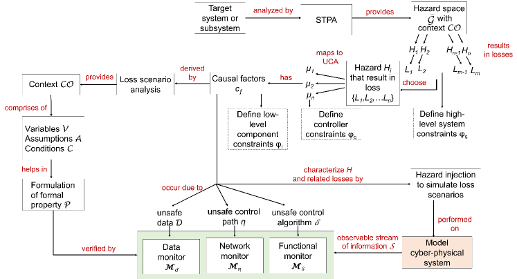
An important motivation for this work is to explore an integrative approach to in-time hazard detection and informed risk that incorporates system level analysis into the design of monitoring architectures. Accordingly, we develop a STPA-driven model-based process for identifying and simulating hazard scenarios for designing multilevel runtime monitors (Fig. 1).
2.1 Losses, Hazards and Unsafe Control Actions
A CPS consists of multiple coordinating components, continuously sensing and processing inputs from the physical domain and human users, and performing software-intensive tasks to produce time-critical outputs. This complex interaction among system components at specific system states increases the possibility of transitioning a system from a safe operating region into an unsafe hazard space . We denote all the identified hazards as . Such hazards can result in losses that include loss of life, damage to property, to name a couple. Higher-level safety constraints (system constraints) are derived from hazard analysis. These safety constraints result in safety requirements that inform the system development stage.
We denote the finite set of all possible control actions with and denote the set of unsafe and the set of safe control actions with . UCAs can drive the system to a hazardous state . Every specific hazard can be related to a finite subset of UCAs denoted by , where . The context, , determines if an action is safe or unsafe. For example, a braking action at a given time may be safe to avoid a collision. Whereas, the same braking action may be unsafe on snowy road conditions as it may be unable to mitigate a collision due to delayed braking. An earlier braking action or a collection of actions may be needed for to be safe in a particular scenario.
Safety constraints (sometimes called controller constraints) and safety requirements are defined at the controller level for all . Although are typically incorporated into a design to prevent a hazard, there can be faults/attacks during operation that can violate the safety requirements imposed by the designer. Furthermore, in some scenarios, cannot be enforced in a system. Runtime safety assurance via monitors is important for promptly detecting safety constraints and requirements violations to prevent a hazard.
2.2 Causal Factors and Relation to Multilevel Monitoring
Finding the possible causes for a specific UCA is an essential step in preventing a hazard . When a violation is detected, providing a timely safe control action can prevent a system from transitioning into the unsafe operating region , consequently avoiding a hazard.
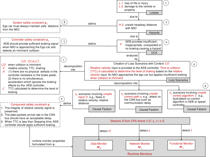
We denote the causes for a UCA as a causal factor . Causal factors are directly related to a given UCA (Fig. 1), where in a given context a causal factor causes the UCA and may lead to the associated hazard . To determine causal factors for each UCA we define loss scenarios, which reveal the context in which hazard may occur. The context has a set of variables which can take multiple values depending on the system state or environment or vehicle conditions, a set of assumptions made on certain variable values, and a set of system conditions of a system based on the variables and assumptions [22]. A unique combination of deviation in values for the variables with a violation of assumptions related to a condition forms the basis for a causal factor for a hazardous control action . Thus, the context can be expressed as a mapping . Once causal factor analysis is complete, low-level component constraints are generated to define the boundary for safe operation at the component level. Components can be both hardware and software, i.e. functional modules such as controllers and other subsystems such as communication buses, sensors etc. in a CPS. Fault/hazard injection approaches are used to strategically inject faults to simulate the deviation in , , and to create loss scenarios and test the boundaries of these constraints.
Further, the causal factors can specifically be related to one of the levels or layers in a multilevel view of the system. STPA provides suggestions for classification of causal factors for hazards that can occur at multiple levels, including controller-based (inadequate control algorithm, flawed control algorithm), input-based (unsafe data from other controllers, failure of sensor inputs), and control path-based (network delays, flaws in data process algorithm in a controller) [14]. For our multilevel monitoring structure, we define the following levels: unsafe data , unsafe processing , and unsafe behavior in the communication path . The causal factors related to unsafe inputs to a controller from sensors, user inputs, or input from another controller as well as unexpected/incorrect data patterns are , where . The causal factors related to flaws in the control algorithm and incorrect functional behavior in the controller are , where . The causal factors related to flaws in the control path through which inputs/outputs are communicated between the subsystems are , where . For timely detection of such causal factors before they result in a UCA , we believe that a viable approach is to employ monitors at these various levels of processing and integration where the vulnerabilities originate.
2.3 Multilevel Runtime Monitoring Framework
Multi-level monitoring extends traditional runtime verification or monitoring by providing a monitor classification or organization schema that maps monitor types to various functions or components in distributed real-time architectures [10]. In this work, we augment a multi-level monitoring framework [9] as it directly addresses monitoring CPS from multiple layer perspectives. A monitor observes streams of time stamped information from a target CPS. A stream, denoted as , where , is a sequence of time-stamped information, from the past instances starting with and ending at the current instance . The subscript denotes a stream associated with a specific part of the system. We denote the set of all streams from different parts of a CPS as , in particular, for all streams .
The streams of information from the CPS that we want to verify as being compliant to safe operation requirements can be represented as a monitorable property derived from component constraints after STPA analysis. The property , also referred to as a monitor specification, is a checking condition that represents the conditions given by a context (Fig. 1), and is most often expressed in temporal logic. Thus, in multi-level monitoring, a monitor of a specific type placed at a specified level detects unsafe or hazardous conditions for the stream it is observing. We classify monitors (and their associated properties) as data, network, or functional monitor types depending on the causal factors and the possible location of emerging hazard states given by STPA. We consider the following three types of monitoring for CPS: input-output (I/O) data-oriented monitors of type , network-oriented monitors of type , functional monitors of type .
-
•
Data Monitor observes streams of data from sensors and actuators that provide an interface to the physical environment, signals behavior of a controller and verifies the data integrity. The causal factors related to , i.e. unsafe input from sensors or from other controllers are verified by .
-
•
Network Monitor verifies the integrity of the data received by the communication layer by observing streams of information from the network layer. They check for signal faults, incorrect signaling protocol, timing delays etc. They observe causal factors related to , i.e. unsafe control path.
-
•
Functional Monitor verifies properties for the system’s functional behavior. For example, the relation between input and output of a controller is verified by a functional correctness property. In particular, observe causal factors related to , i.e., an unsafe control algorithm, by observing streams of information consisting of system states, internal variables, memory read/writes, and event counts.
3 Monitoring an AEB Controller
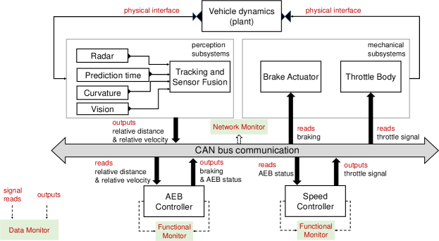
A simplified AEB system model [16] is a representative system for studying the methodology for STPA-driven runtime monitor design (Fig. 2). The output of the AEB controller determines the braking state that decelerates the ego car, which is a car with autonomous features.
A model of the vehicle dynamics module was considered whose output—together with the scenario under consideration—determines the inputs to the radar and vision sensors. The outputs of these sensors are fused to estimate the relative distance and relative velocity between the ego car and the “most important object” (MIO). The MIO is not always the lead car. For example, if a pedestrian comes in front of the ego car, this would be the MIO. Based on these inputs (distance and velocity relative to the MIO), the AEB controller estimates the braking state (Fig. 2). When the ego car is at a safe distance but gets closer required for safe operation, an alert, forward collision warning, is issued. If the driver does not brake or the braking is insufficient, then the AEB engages the “stage I” partial braking (PB1) at a certain critical relative distance. If this does not suffice, “stage II” partial braking (PB2) is applied at a closer relative distance, and then full braking (FB) is engaged. This action decelerates the car to avoid a collision characterized by a minimum headway distance when the velocity of the ego car reaches zero. Runtime monitors of data, network and functional types are placed at different levels in a CPS (Fig. 2).
3.1 STPA for AEB
Losses and Hazards. From our analysis, we consider the losses that must not occur, and the hazards related to the losses are described below. These form the foundation for producing UCAs (Fig. 6). For some of the hazards, we mention sub-hazards to cover different cases. Some illustrative subsets of losses and hazards:
| L-1 | Loss of life or injury due to collision |
|---|---|
| L-2 | Loss via damage to the vehicle or property (repair, fines etc.) |
| L-3 | Loss of reputation |
| H-1 | Unsafe headway distance to the MIO [L-1, L-2, L-3] |
|---|---|
| H-1.1 | Unsafe headway distance to vehicles, pedestrians [L-1, L-2, L-3] |
| H-1.2 | Unsafe headway distance to sidewalks, curb etc. [L-2, L-3] |
| H-2 | Vehicle is traveling at an inappropriate speed. [L-1, L-2, L-3] |
Higher-level system constraints are derived from rephrasing of the hazard statements as a binding mandatory requirement. For example, the system constraint for the hazard H-1 is: “ () The Ego car must always maintain a safe distance to the MIO.”
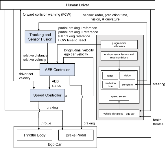
Control Structure Diagram. The STPA control structure diagram shows all the components in the AEB system along with vehicle dynamics and environmental factors. It is a hierarchical control structure with a human driver at the top, brake and throttle controllers in the middle, and mechanical components such as the throttle body and brake pedal at the bottom of the diagram.
Next, we identify UCAs that can occur in the AEB system. This step occurs after loss and hazard determination because UCAs directly cause hazards (Fig. 6). The AEB controller provides a braking signal to the brake pedal, an AEBstatus signal to the speed controller, and forward collision warning (FCW) to the driver (Fig. 3). Braking is a deceleration signal with different braking levels PB1, PB2, and FB (Section 3). Whenever the AEB controller activates the brakes, the AEBstatus signal indicates to the speed controller the braking level applied. AEBstatus 1 indicates “Partial Braking I”, AEBstatus 2 indicates “Partial Braking II”, and AEBstatus 3 indicates “Full Braking”, all as applied by the AEB. Based on the AEBstatus, the speed controller provides or ceases to provide an acceleration signal to the throttle.
Identifying Unsafe Control Actions (UCAs). Based on the control structure diagram analysis, we illustrate a subset of UCAs (Table 1). As an example, we state the controller constraint for UCA 1: “ () AEB must provide a braking signal when MIO is approaching the Ego car and AEB detects an imminent collision [UCA 1].” Here, braking and detection of imminent collision are AEB’s control actions. Finding incorrect or untimely control actions can guide designers towards finding comprehensive loss scenarios and low-level safety requirements for braking and correct detection of imminent collision.
![[Uncaptioned image]](/html/2204.08999/assets/x4.png)
3.2 Loss Scenarios and Causal Factors as Design Guides
for Multilevel Runtime Monitoring
Causal factors for a UCA provide insights on complex subsystem interactions and failure patterns that are critical in developing component-level safety constraints . These low-level component constraints are vital for detection of fault/attack and possible isolation of the causal factors. As a case study, we identify the potential causal factors that result in unsafe braking by the AEB controller and unsafe throttle action by the speed controller. Causal factors for UCAs could be due to a) failures related to the controller, b) inadequate control algorithm, c) unsafe control inputs, and d) inadequate process model as described in the STPA handbook [14]. To determine the causal factors, Fig. 6 explains that we must describe loss scenarios based on each UCA in as to both realize the context and formulate each of the different causal factors . For the AEB system, we describe two scenarios which describe the context for unsafe braking UCA. In each scenario we identify the component level safety constraints based on the illustrated causal factor along with the runtime verification properties used to detect the causal factor . We express the monitor properties using event calculus temporal formal language [21].
Scenario 1: Safe Braking Distance. The vehicle is operating and begins approaching an MIO. The AEB applies braking in accordance with its control algorithm and updates the AEBstatus to a non-zero number corresponding to the level of braking applied. The speed controller applies throttle and ignores the change in AEBstatus. If the speed controller continues acceleration while braking is occurring, the braking components experience undue strain and may fail, leading to potential unsafe headway [H-2] and collision [L-1]. The rationale for simultaneous braking and acceleration from the speed controller’s perspective varies depending on the context in the scenarios. Potential causes include:
- Scenario 1a.
-
The speed controller has an inadequate control algorithm and does not release the throttle when the AEBstatus is non-zero.
- Scenario 1b.
-
The communication between the AEB and the speed controller is delayed. Thus, the speed controller is not aware of the change in AEBstatus, and it keeps the throttle on when the AEBstatus is non-zero.
- Scenario 1c.
-
The AEB does not properly update AEBstatus signal, even after beginning braking [UCA-6,7]. Thus, the speed controller believes the AEB is not braking and keeps the throttle on when the AEBstatus is non-zero.
The context in the scenario can be expressed as a function of , and [22]. For example in scenario 1, throttle and AEBstatus are the variables , the assumption is that the input AEBstatus is accurate and the vehicle is in motion. “Release throttle when AEBstatus is non-zero” is the condition . The component-level safety constraints and their corresponding properties are listed below:
() The Speed Controller should release the throttle when the AEBstatus is non-zero.
Property 1 (Detects inadequate control algorithm in speed controller (Scenario 1a))
“If AEBstatus is equal to 1, 2, or 3, the throttle should be released.” This ensures that the car throttle is not engaged when the brake is engaged by the AEB,
() The data packet’s arrival rate via the CAN bus should have an acceptable delay.
Property 2 (Detects flaw in control path to speed controller (Scenario 1b))
“The time interval between two successive packet arrival via the CAN bus should be less than .” This condition ensures that the consecutive packets and should arrive at time and respectively, where should satisfy the condition ,
() When the AEB controller begins the braking action, the AEBstatus should be updated accordingly.
Property 3 (Detects inadequate control algorithm in AEB (Scenario 1c))
“If deceleration is greater than , the AEBstatus should be non-zero.” This property ensures that the AEBstatus corresponds to the AEB controller’s current braking signal,
Scenario 2: Communication Delay. The vehicle is operating and begins to approach an MIO. There is a communication delay in sending the relative distance and relative velocity signals from the Tracking and Sensor Fusion module to the AEB controller resulting in delayed calculation of Time To Collision (TTC). Because of this, sufficient and timely braking is not applied. The component level safety constraints and runtime property based on this scenario were formulated similar to Scenario 1b to detect delay in communication in the CAN bus.
Hazard Injection and Monitor Detection. Using a model-based fault injection toolbox [12], faults and attacks were injected strategically to simulate the loss scenarios 1 and 2. STPA provides a systematic method to analyze the system and identify loss scenarios. After identifying loss scenarios, we explore adequacy of the causal factor analysis by property-based hazard injection [12].
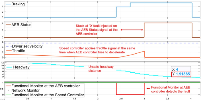
For the first scenario, faults were injected on the AEBstatus signal in the AEB controller (Scenario 1c). Although the AEB controller provides braking action, the speed controller is unaware of the braking and continues to apply throttle due to the fault. This results in simultaneous braking and acceleration of the vehicle, thus causing the unsafe headway distance hazard [H-1]. The headway reduces to 1.9 meters at 4 seconds (Fig. 4) (safe headway distance should be at least 2.4 meters). The functional monitor at the AEB controller detects the fault much earlier than the occurrence of the hazard. This error is detectable only by having a localized monitor at the AEB controller. The functional monitor at the speed controller and the network monitor do not detect such a fault, as a fault on AEBstatus neither changes the functionality of the speed controller nor the network behavior. Thus, having local monitors at each level is beneficial in early detection and isolation of faults/attacks.
For the second scenario, we emulate a malicious node attack where sporadic messages on the CAN bus causes delay in the communication of packets between the tracking and sensor fusion module and the AEB controller. The network-level monitor detects this scenario (Fig. 5). A message injection attack at the network layer also results in violation of a functional property in the AEB controller which verifies the control algorithm at the AEB controller level. The AEB controller decides on the level of braking based on “time to collision” and “stopping time” (time from starting braking to coming to a complete stop). An attack on the network layer results in violation of the functional property when , ego car velocity should be decreasing, thus demonstrating error propagation from one layer to another. While our simulation example confirms that the error is caught both by the network monitor and the functional monitor, the simulation shows that the network monitor detects the error much earlier than the functional monitor at the AEB controller. This use case scenario validates the in-time early detection of the emerging hazard before error propagation reaches the system’s output boundaries. In fact, when a property violation goes unnoticed at one level, they are often detected by another monitor in the hierarchy as effects propagate, thus improving hazard detection coverage.
The workflow integrates requirement elicitation through STPA into the direct creation of runtime monitors by decomposing the causal factors at different system levels on the basis of component safety constraints (Fig. 6). There is an iterative feedback for refinement of safety constraints after hazard injection.
4 Conclusion
We developed an integrative approach to in-time hazard detection that incorporates system-level analysis into the design of runtime monitoring architectures. Integrative approaches to runtime monitoring for hazard detection in CPS are needed to augment the technical basis for DepDevOps style methods. We demonstrated that the systematic nature of STPA hazard analysis is beneficial in deriving and refining multilevel monitoring properties related to causal factors. By developing monitors across multiple system levels, we can accurately detect the origin of a hazard even when it propagates errors across different CPS levels.
In other words, when faults go undetected at their original location, monitors at other system levels can detect propagated errors, thus increasing hazard detection coverage. We also found that MBDE methods and tools significantly improve the productivity of STPA and assist in evaluating runtime monitoring schemes for hazard coverage and refinement.
References
- [1] Ahmed, B.: Synthesis of a Context-Aware Safety Monitor for an Artificial Pancreas System. Master’s thesis, University of Virginia (2019)
- [2] Bakirtzis, G., Carter, B.T., Fleming, C.H., Elks, C.R.: MISSION AWARE: Evidence-based, mission-centric cybersecurity analysis. arXiv:1712.01448 [cs.CR] (2017)
- [3] Combemale, B., Wimmer, M.: Towards a model-based DevOps for cyber-physical systems. In: Proceedings of the 2nd International Workshop on Software Engineering Aspects of Continuous Development and New Paradigms of Software Production and Deployment (DEVOPS 2019) (2019). https://doi.org/10.1007/978-3-030-39306-9_6
- [4] Cui, J., Liew, L.S., Sabaliauskaite, G., Zhou, F.: A review on safety failures, security attacks, and available countermeasures for autonomous vehicles. Ad Hoc Networks (2019). https://doi.org/10.1016/j.adhoc.2018.12.006
- [5] Daian, P., Shiraishi, S., Iwai, A., Manja, B., Rosu, G.: RV-ECU: Maximum assurance in-vehicle safety monitoring. SAE Technical Paper Series (2016). https://doi.org/10.4271/2016-01-0126
- [6] Duan, J.: Improved systemic hazard analysis integrating with systems engineering approach for vehicle autonomous emergency braking system. ASME J. Risk Uncertainty Part B (2022). https://doi.org/10.1115/1.4051780
- [7] Fremont, D.J., Sangiovanni-Vincentelli, A.L., Seshia, S.A.: Safety in autonomous driving: Can tools offer guarantees? In: Proceedings of the 58th ACM/IEEE Design Automation Conference (DAC 2021). IEEE (2021). https://doi.org/10.1109/DAC18074.2021.9586292
- [8] Gautham, S., Bakirtzis, G., Leccadito, M.T., Klenke, R.H., Elks, C.R.: A multilevel cybersecurity and safety monitor for embedded cyber-physical systems: WIP abstract. In: Proceedings of the 10th ACM/IEEE International Conference on Cyber-Physical Systems (ICCPS 2019). ACM (2019). https://doi.org/10.1145/3302509.3313321
- [9] Gautham, S., Jayakumar, A.V., Elks, C.: Multilevel runtime security and safety monitoring for cyber physical systems using model-based engineering. In: Proceedings of the Workshops in Computer Safety, Reliability, and Security (SAFECOMP 2020). Springer (2020). https://doi.org/10.1007/978-3-030-55583-2_14
- [10] Goodloe, A.E., Pike, L.: Monitoring distributed real-time systems: A survey and future directions. Tech. Rep. CR–2010-216724, NASA (2010)
- [11] Haupt, N.B., Liggesmeyer, P.: A runtime safety monitoring approach for adaptable autonomous systems. In: Proceedings of the Computer Safety, Reliability, and Security Workshops (SAFECOMP 2019). LICS (2019). https://doi.org/10.1007/978-3-030-26250-1_13
- [12] Jayakumar, A.V., Elks, C.: Property-based fault injection: A novel approach to model-based fault injection for safety critical systems. In: Proceedings of the International Symposium on Model-Based Safety and Assessment. Springer (2020). https://doi.org/10.1007/978-3-030-58920-2_8
- [13] Leucker, M., Schallhart, C.: A brief account of runtime verification. J. Log. Algebraic Methods Program. (2009). https://doi.org/10.1016/j.jlap.2008.08.004
- [14] Leveson, N., Thomas, J.P.: STPA handbook (2018)
- [15] Liu, Y.A., Stoller, S.D.: Assurance of distributed algorithms and systems: Runtime checking of safety and liveness. In: Proceedings of the 20th International Conference on Runtime Verification (RV 2020). LICS, Springer (2020). https://doi.org/10.1007/978-3-030-60508-7_3
- [16] Mathworks: Autonomous emergency braking with sensor fusion. https://www.mathworks.com/help/driving/ug/autonomous-emergency-braking-with-sensor-fusion.html (2021)
- [17] Redfield, S.A., Seto, M.L.: Verification challenges for autonomous systems. In: Autonomy and Artificial Intelligence: A Threat or Savior? Springer (2017). https://doi.org/10.1007/978-3-319-59719-5_5
- [18] Reich, J., Schneider, D., Sorokos, I., Papadopoulos, Y., Kelly, T., Wei, R., Armengaud, E., Kaypmaz, C.: Engineering of runtime safety monitors for cyber-physical systems with digital dependability identities. In: Proceedings of the 39th International Conference Computer Safety, Reliability, and Security (SAFECOMP 2020). LICS, Springer (2020). https://doi.org/10.1007/978-3-030-54549-9_1
- [19] Sánchez, C., Schneider, G., Ahrendt, W., Bartocci, E., Bianculli, D., Colombo, C., Falcone, Y., Francalanza, A., Krstic, S., Lourenço, J.M., Nickovic, D., Pace, G.J., Rufino, J., Signoles, J., Traytel, D., Weiss, A.: A survey of challenges for runtime verification from advanced application domains (beyond software). Formal Methods Syst. Des. (2019). https://doi.org/10.1007/s10703-019-00337-w
- [20] Schwenger, M.: Monitoring cyber-physical systems: From design to integration. In: Proceedings of the 20th International Conference on Runtime Verification (RV 2020). LICS, Springer (2020). https://doi.org/10.1007/978-3-030-60508-7_5
- [21] Shanahan, M.: The event calculus explained. In: Artificial Intelligence Today: Recent Trends and Developments (1999). https://doi.org/10.1007/3-540-48317-9_17
- [22] Thomas, J.: Extending and automating a systems-theoretic hazard analysis for requirements generation and analysis. Ph.D. thesis, MIT (2013)
- [23] Trapp, M., Schneider, D., Weiss, G.: Towards safety-awareness and dynamic safety management. In: Proceedings of the 14th European Dependable Computing Conference (EDCC 2018) (2018). https://doi.org/10.1109/EDCC.2018.00027
- [24] Zapridou, E., Bartocci, E., Katsaros, P.: Runtime verification of autonomous driving systems in CARLA. In: Proceedings of the 20th International Conference on Runtime Verification (RV 2020) (2020). https://doi.org/10.1007/978-3-030-60508-7_9
- [25] Zhou, X., Ahmed, B., Aylor, J.H., Asare, P., Alemzadeh, H.: Data-driven design of context-aware monitors for hazard prediction in artificial pancreas systems. In: Proceedings of the 51st Annual IEEE/IFIP International Conference on Dependable Systems and Networks, (DSN 2021). IEEE (2021). https://doi.org/10.1109/DSN48987.2021.00058