Time Difference of Arrival Extraction
from Two-Way Ranging
Abstract
Two-Way Ranging enables the distance estimation between two active parties and allows time of flight measurements despite relative clock offset and drift. Limited by the number of messages, scalable solutions build on Time Difference of Arrival (TDoA) to infer timing information at passive listeners. However, the demand for accurate distance estimates dictates a tight bound on the time synchronization, thus limiting scalability to the localization of passive tags relative to static, synchronized anchors. This work generalizes the extraction of Time Difference of Arrival information from a Two-Way Ranging process and enables passive tags to extract distance information from a ranging process, allowing scalable tag localization without the need for static or synchronized anchors. The error due to clock drifts is formally deducted and formulas for the correction of relative clock drifts are derived. The introduced correction formulas reduce the estimation error to the clock drift of one party, resulting in accurate TDoA measurements despite relative clock offset and drift for the Double-Sided Two-Way Ranging and with additional carrier frequency offset estimation, also for Single-Sided Two-Way Ranging.
I Introduction
Measuring the time of flight (ToF) of wireless packets allows devices to estimate their respective distances. The rise of cheap and small ultra-wideband (UWB) transceivers brings this timing-based approach to small and mobile devices, enabling, e.g., indoor real-time location systems in which mobile tags are localized relative to static anchors. Limited by the amount of channel utilization, dense deployments can build upon time differences on arrival (TDoA), allowing the localization of an unlimited number of tags but requiring sufficiently synchronized clocks of static anchors. Hence, scalable solutions like Talla or SnapLoc employ static anchors with a wired backbone for optimal performance [7, 2].
For range estimation in dynamic scenarios, the Two-Way Ranging (TWR) approach allows two active nodes to estimate their distance irrespective of clock offsets by comparing relative time intervals. However, even minor clock deviations challenge the resulting estimation accuracy, with each nanosecond of clock deviation resulting in approximately 30 cm error. In TWR, the relative drift between the active devices remains a major source of error. In case of the traditional Single-Sided Two-Way Ranging (SS-TWR), the carrier frequency offset (CFO) estimation allows a correction of the relative clock drift [1]. Instead of CFO, the Double-Sided Two-Way Ranging (DS-TWR) adds another message to correct relative drifting. With the assumption of a fixed clock drift during the execution of the protocol, both variants can theoretically limit the influence to the drift of one participant.
The TWR and TDoA approaches can be combined to Passive Extended DS-TWR [3] respectively Active-Passive TWR [5]. In these systems, a tag performs TWR with active anchors while additional, passive anchors listen to the exchange. Based on the extracted TDoA values and known distances between anchors, the system then infers the distance between the tag and passive anchors. However, only the CFO estimation reduced the systematic error down to the clock drift of a single device [1]. Further on, tags remain active, thus limiting scalability.
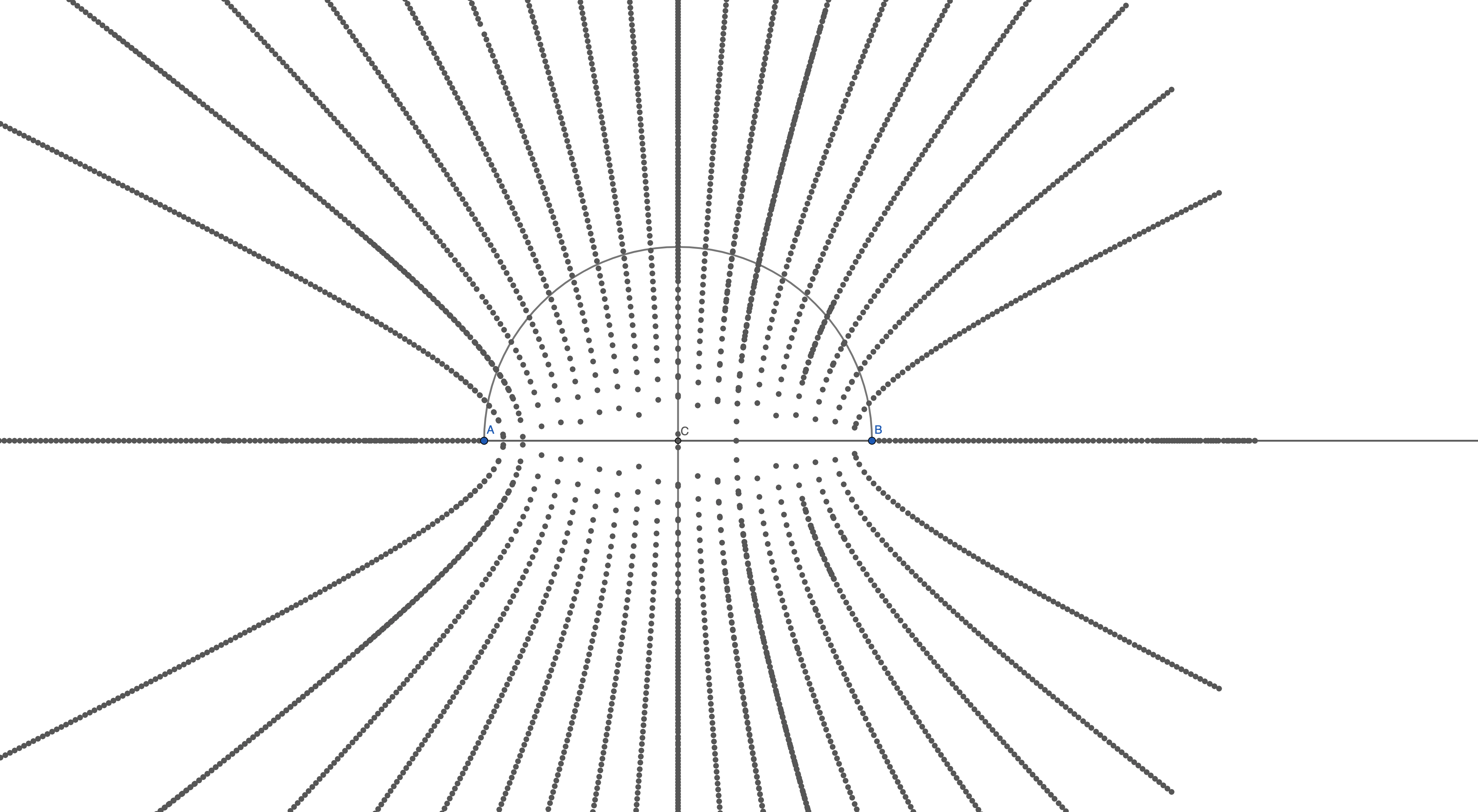
We find that an active TWR exchange allows all listeners to extract the timing difference relative to the active parties, i.e. without the need for known distances. Hence, TDoA extraction can be generalized to passive tags as well. As Figure 1 illustrates, this generalization allows a passive tag to limit its position estimate to a hyperbola relative to the active participants, enabling hyperbolic positioning. In addition, errors due to relative clock drifts can be mitigated even on passive devices. This work therefore revisits and generalizes TDoA extraction from Two-Way Ranging. Covering both the Single- and Double-Sided TWR variant, systematic errors due to relative clock drifts are analyzed and corrected. Overall, this work contributes the following:
-
1.
We introduce a common error estimation and correction formula for SS- and DS-TWR under relative clock drifts.
-
2.
We describe the generalized extraction of TDoA information from listening to a TWR ranging process.
-
3.
We analyze as well as correct the error under relative clock drifts for both SS-TWR and DS-TWR (with and without CFO estimation respectively).
The structure of this work is as follows: Section II introduces the measurement model, the mathematical notation and our unified error analysis and correction for the traditional TWR under relative clock drifts. Then, Section III introduces the passive TDoA extraction with the corresponding error estimation and correction. Section IV summarizes related work. Finally, Section V concludes this work.
II Two-Way Ranging
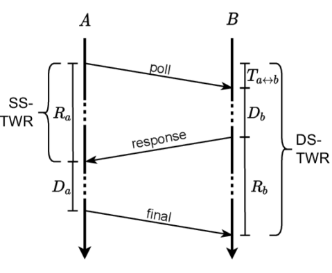
The traditional or Single-Sided Two-Way Ranging (SS-TWR) computes the distance based on one poll and one response message in each direction, measuring the overall round time for the exchange as well as the delay of the other party. Double-Sided Two-Way Ranging (DS-TWR) bases on two interleaved Single-Sided Two-Way Ranging (SS-TWR) rounds: Each side initializes one round with a message while the other responds. As one message is shared between both rounds, three messages are exchanged in total. Figure 2 displays the message exchange for SS-TWR and DS-TWR.
For the ranging of two participants and we denote the respective round time as and the response delays as . Let denote the time-of-flight between participants and . Without loss of generality let initiate the TWR process with and further assume that is computing the distance estimate. Moreover, we assume that messages are timestamped before their transmission. Otherwise, a downstream message could deliver the missing timestamps.
II-A TWR without Clock Drift
Assuming that clocks run with offsets but do not experience different drifts, after the ranging process, can determine the ToF , as it relates to the respective round times as follows:
| (1) |
As both and are durations, both TWR variants can successfully estimate the accurate distance despite clock offsets. Based on Equation (1), for the ToF between and it holds:
| (2) |
However, due to clock imperfections, the clocks tick with different frequencies, probably drifting apart while executing the protocol.
II-B Raw TWR with Clock Drift
We denote the clock drift for as resulting in the factor with and define as the locally measured value of [6]:
For the DS-TWR variant we further define:
We also denote the estimate of as . Plugging our locally measured values directly into Equation (2) yields the raw ToF estimate for TWR:
| (3) |
However, without further correction the clock drifts induce the following error:
| (4) |
Our raw error thus depends on the drifts influencing the components and differently. Note that even in the improbable case of we still get an error in our estimation.
II-C Drift-Corrected TWR
| (5) |
Hence, the error stems from the drift influence on the actual ToF by and the relative drift factor resulting from different clock drifts of and . We can therefore correct our raw ToF estimation with the relative drift factor relative to the clock of :
| (6) |
Comparing this to the actual ToF gives:
| (7) |
So, when we can determine the relative drift factor , we can bring our error down to just the drift during the ToF:
As reordering Equation (1) yields , we can analogously derive the drift corrected ToF for the clock of :
| (8) |
Using for example, Carrier Frequency Offset estimation (CFO) [1], we can determine the relative clock drift factor . As an alternative, the symmetry within DS-TWR can be exploited, requiring an additional message but no CFO estimation. Since assuming that both DS-TWR rounds incorporate the same ToF, it holds that:
| (9) |
Thus, for the actually measured intervals, we derive:
Which can be rearranged to estimate the relative drift factor:
| (10) |
III TDoA Extraction for Two-Way Ranging
Let now be a passive listener to the ranging process, trying to estimate the Time Difference of Arrival (TDoA) between and . This TDoA describes the relative difference of the arrival times as if and sent their messages at the same time, i.e. the difference in ToF to and modeled by . As neither in SS-TWR nor in DS-TWR are and sending at the same time, this TDoA is also called asynchronous (A-TDoA) [1]. Using their ToF and the delays of the TWR process, can relate the respective durations: Assuming that receives the respective messages, it determines as its own experienced time difference between the poll issued by and the response message sent by .
III-A Basic TDoA Extraction
As the poll message from travels simultaneously to and , starts after the initial message from and ends after the response message from . Including the delay , for , the following holds:
| (11) |
thus depends on the ToF between the participants and but also their respective ToF to . Rearranging Equation (11) yields the wanted TDoA:
| (12) |
Replacing with based on Equation (1) gives:
| (13) |
III-B TDoA Relative Drift Correction
Naturally, also the clock of drifts so that determines the local, potentially drifted time :
As before, we can now determine the raw estimate:
| (14) |
And its associated error:
| (15) |
Derived from (15), the error depends on the error in the estimated ToF as well as the relative clock drift between and . However, assuming knowledge of the relative drift factor , we can relate to and correct the relative drift, i.e. based on the clock of :
| (16) |
Obviously, we can also estimate the difference from the perspective of the clock from , also correcting the ToF estimate accordingly:
| (17) |
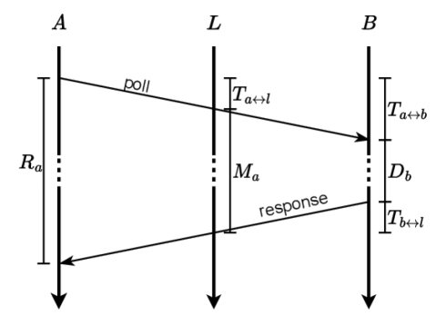
It is important to mention that also can calculate given the necessary measurements as well as and . As with the SS-TWR, could estimate the CFO to approximate the relative drift factors (see Figure 3). Estimating and allows to further compute as follows:
| (18) |
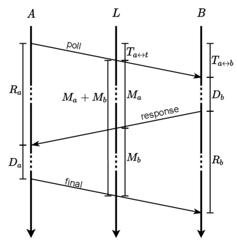
In case that CFO estimation is not possible, the DS-TWR approach includes a second message from , which finishes the second round. As Figure 4 displays, can thus measure the times and for both rounds respectively. Assuming that stays equal during protocol execution, it holds that:
| (19) |
Similarly to Equation (9), can then derive the relative clock drift factor as follows:
| (20) |
Thus, the expected error in the drift-corrected case in times measured by is reduced as follows:
| (22) |
IV Related Work
TDoA measurements constitute the foundation for scalable ranging systems. With its support for an unlimited number of passive devices, TDoA mechanisms are found in Global Navigation Satellite Systems as well as in UWB-based indoor localization [7, 2, 5].
With their Passive Extension to DS-TWR, Horváth, Ill and Milankovich devise a positioning algorithm that employs TDoA measurements from passive anchors [3]. They apply an extended variant of DS-TWR and reduce the influence of relative clock drifts (i.e., the systematic error). Following the multiplication idea of the alternative DS-TWR method [6], Horváth et al. further reduce the systematic error for TDoA measurements [4] but do not decrease it to the drift of a single clock, as shown in this work.
Dotlic, Connell and McLaughlin use the carrier frequency offset estimation within Decawave’s DW1000 module to estimate and mitigate the relative clock offset. They further derive a CFO-based correction formula for TDoA extraction on passive anchors. In comparison, this work extends the TDoA correction to passive tags and further provides the correction for DS-TWR scenarios.
V Conclusion
Using Time Difference of Arrival, listening nodes can increase their positional accuracy or even undertake hyperbolic positioning for fully passiveness, increasing scalability or the frequency of ranging systems. This work described and analyzed the extraction of TDoA information from the TWR process, enabling TDoA measurements without the need for static or synchronized anchors. Using the drift-corrected formulas of Equations (16) and (17), the measurement error can be reduced to the effect of the clock drift from one participant and is thus negligible compared to the accuracy and range of technologies like UWB.
References
- [1] I. Dotlic, A. Connell, and M. McLaughlin, “Ranging methods utilizing carrier frequency offset estimation,” in 2018 15th Workshop on Positioning, Navigation and Communications (WPNC), 2018, pp. 1–6.
- [2] B. Großiwindhager, M. Stocker, M. Rath, C. A. Boano, and K. Römer, “Snaploc: An ultra-fast uwb-based indoor localization system for an unlimited number of tags,” in 2019 18th ACM/IEEE International Conference on Information Processing in Sensor Networks (IPSN). IEEE, 2019, pp. 61–72.
- [3] K. A. Horváth, G. Ill, and Á. Milánkovich, “Passive extended double-sided two-way ranging algorithm for uwb positioning,” in 2017 Ninth International Conference on Ubiquitous and Future Networks (ICUFN). IEEE, 2017, pp. 482–487.
- [4] ——, “Passive extended double-sided two-way ranging with alternative calculation,” in 2017 IEEE 17th International Conference on Ubiquitous Wireless Broadband (ICUWB). IEEE, 2017, pp. 1–5.
- [5] T. Laadung, S. Ulp, M. M. Alam, and Y. Le Moullec, “Active-passive two-way ranging using uwb,” in 2020 14th International Conference on Signal Processing and Communication Systems (ICSPCS), 2020, pp. 1–5.
- [6] D. Neirynck, E. Luk, and M. McLaughlin, “An alternative double-sided two-way ranging method,” in 2016 13th Workshop on Positioning, Navigation and Communications (WPNC), 2016, pp. 1–4.
- [7] D. Vecchia, P. Corbalán, T. Istomin, and G. P. Picco, “Talla: Large-scale tdoa localization with ultra-wideband radios,” in 2019 International Conference on Indoor Positioning and Indoor Navigation (IPIN), 2019, pp. 1–8.