Vortex jets generated by edge defects in current-carrying superconductor thin strips
Abstract
At sufficiently large transport currents , a defect at the edge of a superconducting strip acts as a gate for the vortices entering into it. These vortices form a jet, which is narrow near the defect and expands due to the repulsion of vortices as they move to the opposite edge of the strip, giving rise to a transverse voltage . Here, relying upon the equation of vortex motion under competing vortex-vortex and -vortex interactions, we derive the vortex jet shapes in narrow () and wide () strips [: coherence length, : strip width, : effective penetration depth]. We predict a nonmonotonic dependence which can be measured with Hall voltage leads placed on the line at a small distance apart from the edge defect and which changes its sign upon reversal. For narrow strips, we compare the theoretical predictions with experiment, by fitting the data for m-wide MoSi strips with single edge defects milled by a focused ion beam at distances - nm from the line . For wide strips, the derived magnetic-field dependence of the vortex jet shape is in line with the recent experimental observations for vortices moving in Pb bridges with a narrowing. Our findings are augmented with the time-dependent Ginzburg-Landau simulations which reproduce the calculated vortex jet shapes and the maxima. Furthermore, with increase of , the numerical modeling unveils the evolution of vortex jets to vortex rivers, complementing the analytical theory in the entire range of .
I Introduction
The recent great interest in superconductor thin strips with the critical current approaching the depairing current is caused by the required close-to- bias regime of microstrip single-photon detectors Gol’tsman et al. (2001); Natarajan et al. (2012); Vodolazov (2017); Korneeva et al. (2020); Charaev et al. (2020), ultra-fast vortex motion at large transport currents Puica et al. (2012); Embon et al. (2017); Vodolazov (2019); Kogan and Prozorov (2020); Pathirana and Gurevich (2021); Kogan and Nakagawa (2022), and the phenomena of generation of sound Ivlev et al. (1999); Bulaevskii and Chudnovsky (2005) and spin waves Bespalov et al. (2014); Dobrovolskiy et al. (2021) at a few km/s vortex velocities. In this context, the issue of high is related to blocking of the penetration of vortices via the strip edges Clem and Berggren (2011); Vodolazov (2012); Dobrovolskiy et al. (2020), its control via material and edge-barrier engineering Cerbu et al. (2013); Lösch et al. (2019); Dobrovolskiy et al. (2020), and knowledge of the effects of various edge defects on the penetration and patterns of Abrikosov vortices Buzdin and Daumens (1998); Aladyshkin et al. (2001); Vodolazov et al. (2003, 2015); Sivakov et al. (2018); Budinská et al. (2022).
The penetration of vortices into a superconductor is hampered by various types of surface and edge barriers Brandt (1995), among which the Bean-Livingston Bean and Livingston (1964) and the geometrical Zeldov et al. (1994) barrier are most essential. The former arises due to the attraction of a vortex to its image at distances of the order of the London penetration depth (in bulk superconductors) from the sample surface Bean and Livingston (1964). The geometrical barrier originates from the shape of the superconductor and it appears for samples different from an ellipsoid. In the case of superconductor thin strips with thickness , in which vortices interact mostly via the stray fields in the surrounding space, the vortex-vortex and vortex-image interaction length scale is determined by the noticeably larger effective penetration depth Pearl (1966); Kogan (1994) while effects of the geometrical barrier are not essential Mikitik (2021).
The patterns of moving vortices are determined by their mutual repulsion, interactions with the transport current and structural imperfections in the sample Brandt (1995). For weak-pinning materials – such as amorphous MoSi thin strips used in this work – the effects of volume pinning are not essential. Then, if the Lorentz force [: magnetic flux quantum] exerted on a vortex by the transport current of sheet density exceeds the force of attraction of the vortex to the sample edge, the edge barrier is suppressed. This suppression can be local in the case of a local increase of (current-crowding effect Adami et al. (2013)), and it can be realized, e. g., in strips with an edge defect Buzdin and Daumens (1998); Aladyshkin et al. (2001); Vodolazov et al. (2003); Clem and Berggren (2011); Vodolazov et al. (2015); Dobrovolskiy et al. (2020). In this case, the defect acts as a gate Aladyshkin et al. (2001) for vortices entering into the superconductor strip and crossing it under the competing action of the Lorentz and vortex-vortex interaction forces. If the size of the defect is much larger than the coherence length in the superconductor, the defect can serve as a nucleation point for several vortex chains Embon et al. (2017); Budinská et al. (2022). Such chains form a vortex jet with the apex at the defect and expanding due to the repulsion of vortices as they move to the opposite film edge. If the defect size is , the vortices will be entering into the strip consequentially. However, in the presence of fluctuations and inhomogeneities in the strip, the vortex chain will evolve into a diverging jet because of the intervortex repulsion.
The presence of a vortex velocity component along the superconducting strip gives rise to a transverse voltage , which is also known to appear in the different physical contexts of vortex guiding Niessen and Weijsenfeld (1969); Silhanek et al. (2003); Shklovskij and Dobrovolskiy (2006); Reichhardt and Reichhardt (2008); Wördenweber et al. (2012); Dobrovolskiy et al. (2019) and Hall Vinokur et al. (1993); Lang et al. (2001); Wördenweber et al. (2009); Puica et al. (2009); Zechner et al. (2018); Richter et al. (2021) effects. However, vortex guiding results in an even-in-field transverse voltage while the Hall voltage is odd with respect to magnetic field reversal. The appearance of a non-monotonic was also predicted for the annihilation of a vortex and antivortex entering into the strip via two displaced defects at its edges Glazman (1986) and confirmed experimentally for thin films with a cross-shaped geometry Antonova et al. (1991). The essential differences of appearing because of the vortex jets in the present work is that it is (i) local, i. e., it can only be measured with voltage leads placed rather close to the edge defect, (ii) appears also in zero external magnetic field, (iii) changes its sign with the change of the coordinate of the transverse voltage leads with respect to the edge defect, and (iv) appears because of the repulsion of several (at least two) vortices.
Here, we predict theoretically and corroborate experimentally the appearance of the transverse voltage in the vicinity of an edge defect at zero external magnetic field. We use the dynamic equation for vortices moving under competing vortex-vortex and transport-current-vortex interaction conditions to derive analytically the transverse current-voltage curves . The employed approach is justified at sufficiently large transport currents , i. e., when the edge barrier is suppressed by . The major theoretical results are (i) the nonmonotonicity of as a function of and , and (ii) analytical expressions for the vortex jet shapes in the cases of narrow (, : strip width) and wide () superconducting strips. Furthermore, we use a series of m-wide MoSi strips with artificially created edge defects (notches) milled by a focused ion beam (FIB) at different distances - nm from the transverse voltage leads to experimentally demonstrate the predicted non-monotonicity of . In addition, we augment the analytical and experimental findings with the results of time-dependent Ginzburg-Landau (TDGL) simulations. The obtained vortex patterns reproduce qualitatively the calculated vortex jet shapes and the maxima in and illustrate the evolution of vortex jets to vortex rivers with increase of , complementing the analytical theory in the entire range of transport currents.
The article is organized as follows. The vortex jet shapes and the transverse - curves are derived in Secs. II.2 and II.4 for the cases of narrow and wide strips, respectively. The expression for the vortex velocity in a narrow strip is given in Sec. II.3 and the vortex jet shape in a wide strip in the presence of an external magnetic field is analyzed in Sec. II.5. The evolution of vortex jets to vortex rivers with increase of the transport current is discussed in Sec. II.6 relying upon the TDGL equation modeling. In Sec. III we present the experimental data for thin MoSi strips, discuss them in comparison with the theoretical predictions and the TDGL simulations in Sec. IV, and summarize the major obtained results in Sec. V.
II Theory
II.1 Qualitative consideration
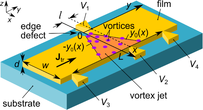
We first consider the problem qualitatively and then proceed to its rigorous theoretical treatment. Our task is to elucidate the appearance of the transverse voltage in a superconducting strip with an edge defect, as schematically shown in Fig. 1. To this end, we consider the following scenario of vortex penetration into the strip with an edge defect. At some current the current density reaches the depairing current density near the defect, the edge barrier vanishes and a vortex enters into the superconductor. The supercurrent circulating around the vortex is directed oppositely to near the defect, resulting in a locally smaller and a recovery of the edge barrier, thereby preventing the penetration of other vortices. The recovery of the edge barrier is temporary since the vortex moves toward the opposite edge of the strip due to the transport current. The vortex motion is accompanied by a redistribution of the transport current such that reaches again and another vortex enters into the strip.
In principle, in a pure uniform strip in the absence of a current density gradient and/or fluctuations, the second vortex should move along the same trajectory as the first vortex since the first vortex does not create a perpendicular component of the driving force acting on the second vortex. Moreover, the first vortex creates a wake behind it, i. e., some track with a suppressed superconducting order parameter, which attracts the second vortex. The strength of the wake is determined by nonequilibrium effects, the time-of-flight of the vortex across the strip and, hence, by the magnitude of the transport current.
However, in the presence of fluctuations and inhomogeneities – which cannot be avoided even in high-quality samples – the second vortex may escape from the wake and the vortex repulsion (which is especially strong in narrow strips) will deflect the trajectory of the second vortex away from the trajectory of the first vortex. This deviation of the vortex trajectories away from the transverse-to-strip direction (-axis) will lead to the appearance of a vortex jet, as depicted in Fig. 1. Accordingly, when the edge defect is located at a distance from the line , the crossing of this line by vortices leads to the appearance of a transverse voltage . In particular, when exceeds by only a small amount, the vortex-interaction-induced longitudinal velocity component, , is relatively large in comparison with the Lorentz-force-induced transverse velocity component . In this regime, since the number of vortices crossing the line per unit of time increases as . By contrast, the Lorentz-force-induced perpendicular velocity component dominates the vortex dynamics at . In this regime, for the line located not too close to the defect, though the velocity of vortices is still increasing with increase of , the number of vortices crossing the line is decreasing faster. The competition between these two contributions leads to the appearance of a maximum in and a decrease of to zero with a further increase of .
In our hydrodynamic approximation with respect to the density of vortices and their velocity field, which allows for analytical expressions for the vortex jet shapes and the transverse - curves, we will keep only the minimal number of essential terms which provide a non-monotonic dependence . Namely, these are the vortex-vortex and transport-current-vortex interactions. In particular, we will neglect the interaction of vortices with the strip edges which could lead to quantitative corrections in the final expression, especially in the case of narrow strips.
II.2 Vortex jet in a narrow strip
In this subsection, we consider the case of a thin narrow superconducting strip with thickness and width carrying a transport current in the absence of an external magnetic field. The geometry of the problem is shown in Fig. 1. The origin of coordinates is associated with an edge defect acting as a place of entry of vortices into the strip. We consider the regime of sufficiently large transport currents , where is the current at which the edge barrier is suppressed.
We assume that the force of interaction of a vortex located at the point () with a vortex located at the origin of coordinates is given by the expression Pearl (1964); de Gennes (1966)
| (1) |
where is the magnetic flux quantum. This force can be expressed as a gradient of the interaction potential Blatter et al. (1994) . For an ensemble of vortices located at points , the total interaction potential is given by
| (2) |
With the two-dimensional vortex density the interaction potential can be expressed as
| (3) |
A stationary flow of vortices in the strip implies . The vortex trajectory can be found from the equation of the balance of forces acting on the vortex
| (4) |
where is the two-dimensional transport current density, the unit vector perpendicular to the strip plane, the viscosity coefficient, and the vortex velocity. Note that in the considered case of a narrow strip with the transport current density is constant over the width of the strip. The width of the vortex jet depends on the coordinate and is equal to .
We assume that the vortex density is constant over the jet cross-section, that is . In this case, the flux of vortices, which coincides with their frequency of penetration into the strip, is given by
| (5) |
where . In what follows we consider rather large transport currents which result in large vortex velocity components along the -axis. This allows us to limit our consideration by the case of narrow jets with and to simplify Eq. (3) as
| (6) |
from where
| (7) |
The equations of motion of the vortex and yield the equation for the vortex trajectory
| (8) |
The trajectories of the vortices at the edges of the jet are determined by the condition , from where one obtains
| (9) |
where is the divergence angle of the jet. The integration constant is taken equal to zero since the size of the edge defect is assumed to be much smaller than the width of the vortex jet at (see Fig. 1). It can be shown that the vortices inside the jet move along straight lines with slopes . The above assumption is justified in the case of a narrow vortex jet, that is, when .
Let the voltage leads and be located in such a way that their -coordinates are equal to , and is larger than the -size of the edge defect, see Fig. 1. Then, if the trajectories of vortices in the jet cross the dashed line , the transverse voltage is induced between the leads and . The appearance of the transverse voltage follows from the following considerations. The longitudinal voltage on the strip is determined by the average rate of change of the phase difference of the order parameter at its edges
| (10) |
As one vortex passes through the strip, the phase difference of the order parameter taken at two points located on both sides of the row of moving vortices evolves by . Thus, the longitudinal voltage is proportional to the vortex flux . Accordingly, the transverse voltage is determined by the part of the flux of vortices that crosses the line , namely, , where and . For the calculation of we make use of the dependence observed experimentally Embon et al. (2017) for an edge defect in the form of a narrowing of the film. Using Eq. (9) for and substituting , we obtain the sought-for expression
| (11) |
where is the coefficient of proportionality between and for sufficiently large .
II.3 Vortex velocity in a narrow strip
In recent years, thin strips in which vortices can move at high velocities have attracted great attention Embon et al. (2017); Dobrovolskiy et al. (2020); Leo et al. (2020); Ustavschikov et al. (2020); Kogan and Prozorov (2020); Pathirana and Gurevich (2020, 2021). This raises the problem of measuring the velocity of vortices moving under the action of the Lorentz force. We note that in a narrow strip, the -component of the vortex velocity is inversely proportional to the divergence angle of the jet . In experimentally measured quantities, the expression for the vortex velocity reads
| (12) |
where is the longitudinal voltage on the strip and is the current value at which vanishes.
The vortex velocity in a narrow strip can, therefore, be estimated from measurements of the transverse voltage . Indeed, if a pair of voltage leads is located at a distance from the axis , then with an increase of the transport current, will become zero for a given . By substituting and into Eq. (12) the velocity can be calculated.
II.4 Vortex jet shape in a wide strip
In this section, we consider the case of a thin wide superconducting strip with thickness and width carrying a transport current in the absence of external magnetic field. Instead of re-deriving all the expressions completely, we rather outline the modifications of the results presented in Sec. II.2 for the case of wide strips.
The distribution of the transport current density over the width of a wide strip has the well-known form Rhoderick and Wilson (1962); Larkin and Ovchinnikov (1971)
| (13) |
where is the total transport current flowing in the strip. Equation (13) is inapplicable at distances of the order of from the strip boundaries. However, this drawback is insignificant for the subsequent analysis of strips with .
In the case of wide strips, the velocity in Eqs. (5)–(8) is replaced by , where (not too close to the strip edges)
| (14) |
Since the -component of the vortex velocity in wide strips depends on the coordinate , , one obtains the following equation for the vortex trajectory
| (15) |
As in the case of narrow strips, the jet boundary is determined by the condition , from where one obtains
| (16) |
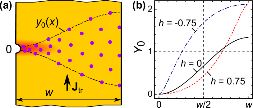
The shape of the vortex jet is largely determined by the Lorentz force. Near the edges of a wide strip, where the current density and, hence, the Lorentz force are relatively large, the curve has a low inclination. Near the center of the strip, where the Lorentz force decreases, the dependence becomes steeper. Thus, in a wide strip, the diverging jet of vortices is bounded by the curves with inflection points at . The vortex jet shape determined by Eq. (16) is in qualitative agreement with the shape of the vortex patterns observed by scanning SQUID-on-tip microscopy Embon et al. (2017) in Pb bridges with a narrowing, see Fig. 2(a) and the inset in Fig. 3(b) in Ref. Embon et al. (2017).
Note that in the approach used it is hardly possible to obtain perfect agreement between theory and experiment, since we use Eq. (1) which quantitatively describes the interaction of vortices in a narrow strip where the distance between vortices . At the same time, the use of our approach is not unreasonable for the description of wide strips. An argument in its favor is the small width of the vortex jet, since in a jet with a width of less than , its expansion is mainly caused by the repulsion between vortices located at distances less than . Equation (15) implies that the trajectories of vortices inside the jet are given by the equality , where parameter .
In the case of a wide strip, the transverse voltage is given by
| (17) |
It is seen that has, again, a nonmonotonic behavior. At large currents , such that , is equal to zero.
II.5 Vortex jet shape in a wide strip in a magnetic field
In this subsection we analyze the evolution of the vortex jet shape in a wide strip in the presence of an external magnetic field. Namely, when a magnetic field is applied perpendicular to the plane of a wide strip, a Meissner screening current is induced in the superconductor, modifying the shape of the vortex jet. In this subsection, for convenience, we assume that the strip occupies the region , where is the dimensionless coordinate . Then, in the Meissner state, the current density has the form Larkin and Ovchinnikov (1971)
| (18) |
where is the projection of the applied magnetic field onto the -axis. If one introduces the dimensionless magnetic field , then the dependence reads
| (19) |
Figure 2(b) shows the coordinate dependence at three values of the reduced magnetic field . Note that the shape of the vortex jet strongly depends on the polarity of the applied magnetic field. Indeed, at , the direction of the screening current coincides with the direction of the transport current in the region , which increases the Lorentz force acting on the vortex. By contrast, the same currents are oppositely directed at , which leads to a decrease of the Lorentz force. When , the situation changes to the opposite, since now the currents flow in the same direction when and in the opposite directions when .
II.6 Vortex jet in the TDGL model
The theoretical consideration in Secs. II.2-II.5 is based on a hydrodynamic approach, wherein the vortex distribution is described in terms of the vortex density. This model allows for the analytical expressions for the vortex jet shapes and the transverse - curves. However, the hydrodynamic approximation is connected with the unknown condition for the vortex entry frequency via the edge defect. Besides, it is difficult to take into account nonequilibrium effects associated with the fast vortex motion at large transport currents.
As a complement to the analytical model introduced above, one can take a discrete approach in which vortices enter the strip via the defect one by one. This approach is based on the TDGL equation which is solved in conjunction with the heat conductance equation. Though no analytical expressions are available for the vortex jet shapes and the transverse - curves in this model, it takes into account both, the condition for the vortex entry frequency and nonequilibrium effects Budinská et al. (2022). In addition, it allows for analyzing the vortex patterns relying upon the spatiotemporal evolution of the superconducting order parameter .
Our model is valid at and for short electron-electron scattering times . The latter condition implies that at any time instant, electrons are thermalized among themselves and one may introduce an electron temperature differing from the phonon temperature and the substrate temperature . However, if is comparable with the inelastic electron-phonon scattering time (even if is reduced due to the electron-electron interaction) the used model can give only qualitative predictions.
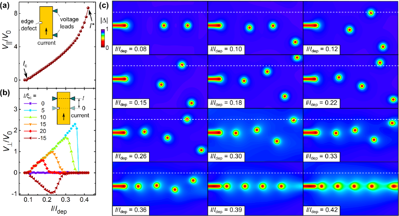
In the TDGL simulations, we consider a superconducting strip with dimensions () where nm for MoSi thin strips. Here, is the electron diffusion coefficient and is the superconducting transition temperature. We use the normal metal-superconductor boundary conditions at the ends of the strip (along the -axis), which allow us to employ a simple method for injecting the current into the superconductor, and the boundary conditions with vacuum along the -axis. Details on the considered equations and the numerical procedure were reported elsewhere Budinská et al. (2022). The edge defect was modeled as a region (slit) with a local suppression of . The size of the defect was chosen as (), as shown in Fig. 3.
Figure 3(a) and (b) show the calculated and curves for the superconducting strip in a weak magnetic field , where . This magnetic field is slightly below the field , at which there is one sparse row of vortices at for a strip of length while for a strip of length there are two vortices, see Fig. 3. The physical meaning of is half of the magnetic field magnitude at which the edge barrier for vortex entry is suppressed at . In the simulations, the weak magnetic field is applied to increase the number of vortices in the sample in the resistive state and to expand the range of currents () of the low-resistive regime which precedes the transition of the strip to the normal state. The application of this small magnetic field allows us to illustrate better the main results.
The evolution of the vortex patterns with increase of the transport current is presented in Fig. 3(c). Namely, we find that at two vortex rays are formed – one is deflected toward positive values and another one in the direction of negative values with respect to the edge defect. With an increase of the points, where vortices exit the strip at the opposite edge, are displaced toward so that the two vortex rays approach each other. Once the vortex ray stops passing through the line , decreases to zero. Overall, the most essential features of the transverse - curves in Fig. 3(b) can be summarized as follows: for . The curve exhibits a maximum in the current range . The magnitude of the maximum in decreases with increase of . The voltage changes its sign upon reversal.
Qualitatively, the same results were obtained for smaller and zero magnetic fields. The only quantitative difference is that the number of vortices and the divergent angle between the vortex rays is smaller than that shown in Fig. 3. For instance, at only two vortices (one in each ray) are in the strip, but the shape of is similar to that shown in Fig. 3(b). By contrast, with increase of the magnetic field, the number of vortices increases, which leads to a wide vortex jet instead of just two vortex rays. In this regime, the vortices may exit at different points on the opposite edge of the strip and this regime is realized already at . At larger magnetic fields, when exceeds some further threshold value, vortices may enter not only via the edge defect but also at other points along the sample edge because of the suppression of the edge barrier. This regime requires further investigations which are beyond the scope of the present work.
III Experiment
III.1 Samples
The theoretical predictions for narrow strips were examined for a series of 15 nm-thick m-wide MoSi strips differing by the location of an artificially-created edge defect (notch) with respect to the perpendicular voltage leads, see Fig. 1 for the geometry. MoSi was chosen as an amorphous superconductor with a high structural uniformity and a very weak intrinsic (volume) pinning, as previously concluded from the structural characterization of the strips by transmission electron microscopy and the magnetic-field dependence of the critical current Budinská et al. (2022). The MoSi films were deposited by dc magnetron co-sputtering of Mo and Si targets onto Si/SiO2 wafers, on top of a nm-thick Si buffer layer, and covered with a nm-thick Si layer to prevent the strip oxidation.
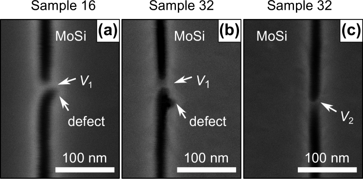
For electrical resistance measurements the films were patterned into six-probe geometries (Fig. 1), with a strip length m and width m. The voltage leads, with a width of about nm, were milled by FIB in a dual-beam high-resolution scanning electron microscope (SEM: FEI Nova NanoLab 600). FIB milling was done at kV/ pA with a pitch of nm. In our previous study of the edge-barrier effects on the vortex dynamics in wide MoSi strips Budinská et al. (2022) we revealed that FIB milling allows for the realization of very smooth strip edges. Specifically, the rms edge roughness in the -direction was less than nm, as deduced from the inspection of the strips by atomic force microscopy over a distance of nm along the edge. The milling of the edges was accompanied by stopping of Ga ions within a region of width nm along the edges, as inferred from SRIM simulations and seen as lighter regions along the strip edges in the SEM images in Fig. 4.
The strips have a superconducting transition temperature K, resistivity cm, upper critical field T, and T/K near , yielding the electron diffusion coefficient cm2/s, the coherence length nm, the penetration depth nm, and m. Thus, the investigated strips are thin and narrow, with and . With the temperature dependence of the effective penetration depth Tinkham (2004), we make an estimate for m in our experiments at K. Hence, the large in conjunction with the weak intrinsic pinning ensures that the dynamics of vortices entering via the edge defects is dominated by the transport-current-vortex, vortex-edge and vortex-vortex interactions. Altogether, this renders the MoSi strips as a suitable experimental system for the examination of the theoretical predictions of Sec. II.2.
III.2 Longitudinal - curves
The - curves were taken in the current-driven regime. The absolute value of the magnetic field in the vicinity of the sample was always smaller than T, as controlled by using a calibrated Hall sensor and representing zero-field conditions in our experiment. In what follows, we present the data for four samples, in which the middle of the notch was located at the distances , , , and nm from the line between the transverse voltage leads. The samples are labeled as Sample 16, Sample 32, Sample 48, and Sample 80, corresponding to the parameter , , , and , respectively. Also, an additional Sample A without an artificial defect was used for reference purposes. Due to the small distances between the notch and the voltage lead (close to the resolution limit for Ga FIB milling) multiple nominally identical structures were fabricated. SEM images of the close-to-notch regions of the strips chosen as Samples 16 and 32 for transport measurements are shown in Fig. 4.
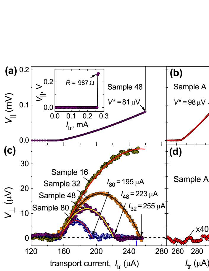
Figure 5(a) presents the longitudinal - curve for Sample A and Sample 48. The latter - curve, within deviations of less than the symbol size, is representative for the - curves of all samples containing a notch. Both - curves in Fig. 5(a) exhibit a zero-voltage plateau up to some critical current , which is A for Sample 48 and A for Sample A. The values were determined by using the V voltage criterion, as illustrated in Fig. 5(a). Suppression of the edge barrier at enables the penetration of vortices into the strips, resulting in rapid onsets of the low-resistive regime up to the abrupt jump to the highly-resistive state. These jumps occur in consequence of the flux-flow instability (FFI) Larkin and Ovchinnikov (1975, 1986); Bezuglyj and Shklovskij (1992) at the current A for all samples with a notch. The instability current for Sample A is by about higher, A, and the instability voltage for Sample A is also higher by about . These findings are in line with our previous observations for m-wide superconducting Nb-C strips with and without edge defects Dobrovolskiy et al. (2020).
III.3 Critical current and its field dependence
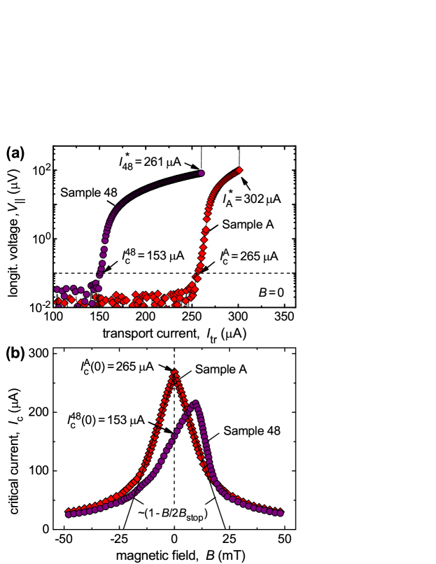
Figure 5(b) shows the field dependences of the critical current for Sample A and Sample 48. The presence of a notch leads to a reduction of the critical current at and to a shift of the maximum in the originally symmetric under -reversal to about mT. At negative fields, the notch locally suppresses the edge barrier and thereby facilitates the entry of (anti)vortices. This leads to a small reduction of up to mT at which the role of the volume pinning increases. At positive fields, when the vortices enter the microstrip from the opposite side, the notch does not affect the vortex entry and this is why is not affected by the presence of the notch at mT.
The linear dependence at is indicative for a vortex-free (Meissner) state. Hence, with increase of the penetration of vortices is controlled by the locally suppressed edge barrier at the notch. In particular, for Sample A, fits the dependence with mT, above which decreases as . We note that for our microstrip a current A induces a self-field mT which is much smaller than and, hence, the contribution of possible self-field effects to the observed crossover in at mT is negligibly small.
With the temperature dependence of the depairing current , where for dirty superconductors Romijn et al. (1982); Clem and Kogan (2012); Budinská et al. (2022) [: superconducting gap at zero temperature, : sheet resistance] and the BCS ratio we obtain mA and A for our MoSi strips. This yields , attesting to a strong local reduction of the barrier for vortex entry in the strips with an edge defect in comparison with Sample A, for which A yields . Sample A has likely intrinsic edge defects, because its critical current is smaller than the theoretically expected depairing current. Moreover, we expect that the largest single defect suppresses as well since is close to . This is representative for all samples with notches, for which we assume the simultaneous motion of several vortices across the strip. Importantly, for all samples with a notch, the instability current A is smaller than the critical current A for Sample A. This ensures that in the entire range of currents of our interest (-A) the penetration of vortices occurs via the notch, as considered in the theoretical model.
III.4 Transverse - curves
The transverse - curves for all samples are presented in Fig. 6(c). The transverse voltage is zero in the same range of currents as in Fig. 6(a), and it exhibits a maximum in the regime of linear dependence . The maximum magnitude of is by about a factor of two smaller than the magnitude of . The curves for Samples 80, 48, and 32 exhibit a zero plateau above some threshold current (indicated in Fig. 6(c)), which shifts toward larger currents with decrease of . For Sample 16, the dependence attains a maximum followed by a jump of to V upon the transition of the sample to the highly-resistive state.
Figure 6(d) presents the transverse - curve for sample A. While for all samples with an edge defect exhibit a maximum in the regime of linear dependence , the transverse voltage for Sample A fluctuates around the instrumental noise level in our setup up until the sample transition to the highly-resistive state at . Accordingly, the occurrence of the maxima in can be clearly attributed to the presence of the milled notches rather close to the line in Samples 16, 32, 48 and 80. The transverse voltage below nV in Fig. 6(d) also suggests that possible intrinsic edge defects are far away from the transverse potential leads in Sample A.
IV Discussion
IV.1 Applicability of the model
In Secs. II.2 and II.4 we have analyzed the shape of vortex jets in narrow and wide strips and phenomena that arise due to the difference between the vortex jet and the vortex chain. It should be noted that the case of a superconducting strip in the Meissner state under consideration is different from the often studied case of vortex penetration into a strip that is in the critical state, where vortex avalanches (dendrites) are observed Aranson et al. (2001); Altshuler and Johansen (2004); Aranson et al. (2005); Brisbois et al. (2016, 2017); Shaw et al. (2019); Jiang et al. (2020); Colauto et al. (2021). The considered regime is also different from the case of strips with rather strong intrinsic pinning at low magnetic fields, where the flux does not penetrate with a smooth advancing front, but instead as a series of irregularly shaped protrusions, resulting in at Grimaldi et al. (2010).
It is natural to assume that in the superconducting strip with one edge defect and zero applied magnetic field the vortices penetrate into the superconducting strip sequentially one after another via defect and form a vortex chain moving from one edge of the strip to another. Indeed, vortices move perpendicular to the edge of the strip due to transport current and there is no perpendicular component of the force (along the strip) due to other vortices (all vortices move along the same straight line connecting opposite edges of the strip). However, in the presence of fluctuations or inhomogeneities, this regime is unstable at not very large velocities, i. e., when there is no channel with a suppressed order parameter, which appears either due to a finite relaxation time of the superconducting order parameter or due to heating. Due to the vortex-vortex repulsion, even small deviations of the trajectory of one vortex from the straight line lead to an instability of the whole vortex chain and the formation of a vortex jet.
Previously, it was shown that in the case of vortex flow in a narrow region across the superconducting strip (vortex river), the effects of self-heating play an important role Bezuglyj et al. (2019). When the vortices are injected through an edge defect, the heating of the vortex jet region leads to a decrease of the absolute value of the order parameter in this region and, therefore, to the lateral thermal pinning of the vortex jet. Such a thermal pinning justifies the assumption about the constancy of the vortex density in the cross-section of the jet.
Note that splitting of vortex chains was revealed in the past for fast-moving vortices when one vortex river splits up into several rivers at a large current density gradient across the bridge/strip width Embon et al. (2017); Vodolazov and Peeters (2007). By contrast, in the system considered in the present work, the current crowding near the small defect at the edge of a straight strip is localized near the defect and the current gradient near the edge has a small impact on the vortex dynamics. In particular, it was impossible to reproduce vortex jets in TDGL simulations (at zero or very weak magnetic fields) in the absence of fluctuations while vortex jets appeared in weak magnetic fields. In the latter case, the vortices already present in the strip lead to the instability of the vortex chain. A further distinctive feature of our work from the wide bridges with narrowing considered in Ref. Embon et al. (2017) is that in the regime of high vortex velocities, vortex jets appear in Ref. Embon et al. (2017), whereas vortex jets vanish evolving to vortex rivers in our work.
One of the conditions for the applicability of the analytical model is the smallness of the intervortex distances in comparison with the characteristic scales of the problem. This means that the vortex density must satisfy the following strong inequality: . Substitution of the density of vortices and the width of the jet into this inequality yields . Thus, for the model to be valid, the frequency of penetration of vortices into the strip must be sufficiently high. At the same time, it turns out that at a current A, due to the small width of the film, the average distance between the vortices is of the order of the coherence length. This means that the condition for the applicability of Eq. (1) is not satisfied, and only a qualitative description of the experiment on m-wide films can be expected from the presented model.
IV.2 Evaluation of the experiment
In the theoretical model of Sec. II.2, the edge-barrier effect on the vortex motion was neglected. This effect is most profound in narrow strips, leading to in high-quality samples. Phenomenologically, it can be accounted for by assuming that the average (over the strip width) vortex velocity , as observed experimentally for an edge defect in the form of a narrowing of the film Embon et al. (2017). Indeed, the attraction of vortices to the edges can be described mathematically via the introduction of vortex images Brandt (1995). We note that one can neglect the influence of the strip edges in Eq. (4) when , since the vortex-vortex interaction decays with the distance as already at Brandt (1995). However, the edge barrier strongly affects the time-of-flight of the vortex across the strip since near the edge where it enters the vortex moves very slowly and diverges when while .
Thus, we used the dependence for fitting the experimental data (symbols in Fig. 6(c)) to the expression following from Eq. (11), varying the coefficients and as two empirical parameters. The best fits were obtained for V/A and mV/mA2. The fits shown by solid lines in Fig. 6(c) reproduce well the dome-shaped maxima in the experimental dependencies for all samples. Note that the agreement of the experimental with the parabolic dependence following from the theory indicates that, in our case, the edge defect injects an expanding jet of vortices rather than a chain of vortices.
Figure 6(a) presents the longitudinal - curve for Sample 48, emphasizing that the maximum in occurs in the quasi-linear regime of and there is some range of currents (-A) in which while . Thus, indeed, at sufficiently large corresponding to sufficiently large vortex velocities , the trajectories of vortices do not pass through the line . Finally, we note that the maximal magnitude of is decreasing with increase of the distance between the edge defect and the line . This attests to a local character of , as predicted by the theory.
The values in Fig. 6(c) were also used to make estimates for the vortex velocity, as suggested theoretically in Sec. II.3. Using Eq. (12), in which is replaced by ), we obtain for A the vortex velocity km/s. This value is an order of magnitude greater than the maximal vortex velocities in Refs. Embon et al. (2017); Budinská et al. (2022). We attribute the overestimation of the vortex velocity to the specific dynamics of the order parameter. Namely, a rapidly moving vortex leaves behind a region with a suppressed order parameter for some time, and this region attracts subsequent vortices Glazman (1986). As a result, the vortex jet narrows, and this narrowing is interpreted (based on Eq. (12)) as an increase in the vortex velocity.
The TDGL simulations suggest that in the broad range of transport currents corresponding to , the number of vortices moving in the strip at each time instant is almost the same, see Fig. 3. Herewith, the constancy of the average number of vortices in the strip at a given means that the penetration of vortices into the strip (at the frequency ) occurs with the same frequency as the inverse of the time-of-flight needed for a vortex moving with velocity to cross the strip of width Dobrovolskiy et al. (2018). Accordingly, if one assumes the motion of a single vortex and uses the Josephson relation , then the relation and the experimentally measured V at yield km/s if were associated with the motion of only one vortex. However, it is obvious that a vortex jet cannot be formed by one vortex. In particular, for our MoSi strips at the TDGL model predicts the presence of three vortices as . However, this model also predicts while in the experiment . For three vortices moving in the strip, the instability velocity can be estimated as km/s.
There are two arguments in favor of this estimate: (i) Instability velocities of about km/s were recently deduced at mT for m-wide MoSi thin strips which exhibit an instability current of mA Budinská et al. (2022). At this field the number of vortices could be estimated via magnetic flux passing through the strip, from the standard relation . The scaling of the instability currents at zero field with the strip width within the framework of the edge-controlled FFI model Vodolazov (2019); Dobrovolskiy et al. (2020) suggests to expect A, which is indeed rather close to A for the reference m-wide MoSi Sample A without an edge defect.
(ii) The vanish of at A for Sample 32 implies that, at close-to-instability currents, the angle of deviation of the vortex trajectories from the line is less than . This means that at such large currents the vortices move in a chain which then develops into a vortex river – a chain of vortices with the depleted vortex cores because of the retarded relaxation of quasiparticles outside the vortex cores. If one makes an estimate for the energy relaxation time of quasiparticles (normal electrons) left by fast-moving vortices, than three vortices in a vortex river, whose development into a normal domain mediates the onset of FFI, would have a separation of about nm. In this case would yield ps which is in line with ps Budinská et al. (2022) deduced within the framework of the FFI theory Larkin and Ovchinnikov (1976, 1986); Bezuglyj and Shklovskij (1992), generalized by Doettinger et al Doettinger et al. (1995), for the m-wide strips made from the same MoSi strips.
V Conclusion
To sum up, we have predicted theoretically and corroborated experimentally the appearance of the transverse voltage in the vicinity of an edge defect in superconducting strips at rather large transport currents in zero magnetic field. This voltage is local, i. e., it can be measured with transverse voltage leads placed at a rather small distance apart from the edge defect and it changes its sign upon reversal. The physical origin of is related to the motion of vortices penetrating via the edge defect into the superconducting strip and forming a diverging vortex jet as they move to the opposite edge of the strip. Due to the different distribution of the transport current over the width of the strip, the shape of the jet of vortices in a wide strip (Eq. (16) and Fig. 2) is qualitatively different from the shape of the vortex jet in a narrow strip (Eq. (9) and Fig. 1).
The developed analytical model relies upon the dynamic equation for vortices moving under competing vortex-vortex and transport-current-vortex interactions and it is justified at sufficiently large transport currents when the edge barrier is already suppressed. The major theoretical results obtained in the present work are (i) the analytical expressions (9) and (16) for the vortex jet shapes in narrow and wide superconducting strips, respectively, and (ii) the transverse - curves for the cases of narrow (Eq. (11)) and wide (Eq. (17)) superconducting strips. For wide strips, the derived vortex jet shape is in qualitative agreement with the recently observed patterns of fast-moving vortices in Pb bridges with a narrowing Embon et al. (2017).
For narrow strips, the theoretical predictions were compared with experiment, by fitting the data for m-wide MoSi strips with artificially created edge defects (notches) milled by FIB at different distances from the transverse voltage leads. The analytical and experimental findings have been further augmented with the results of TDGL simulations which reproduce qualitatively the calculated vortex jet shapes and the maxima in the curves. In addition, the TDGL equation modeling results have allowed us to illustrate the evolution of vortex jets to vortex rivers with increase of , complementing the analytical theory in the entire range of transport currents.
Acknowledgment
A.I.B. is grateful to L.N. Davydov for discussions. O.V.D. thanks M. Huth for providing access to the dual-beam microscope and to R. Sachser for support with the nanofabrication. V.A.S. and M.Yu.M. acknowledge the Wolfgang Pauli Institute (WPI) Vienna for Scholarships within the framework of the Pauli Ukraine Project. M.Yu.M. acknowledges the Scholarship from the Krzysztof Skubiszewski Foundation. B.B. and B.A. acknowledge financial support by the Vienna Doctoral School in Physics (VDSP). V.M.B. acknowledges the European Cooperation in Science and Technology (E-COST) for support via Grants E-COST-GRANT-CA16218-5759aa9b and E-COST-GRANT-CA16218-46e403c7. D.Y.V. acknowledges state contract No. 0035-2019-0021. This research is funded in whole, or in part, by the Austrian Science Fund (FWF), Grant No. I 4865-N. Support by E-COST via COST Actions CA16218 (NANOCOHYBRI) and CA19108 (HiSCALE) is gratefully acknowledged.
References
- Gol’tsman et al. (2001) G. N. Gol’tsman, O. Okunev, G. Chulkova, A. Lipatov, A. Semenov, K. Smirnov, B. Voronov, A. Dzardanov, C. Williams, and R. Sobolewski, “Picosecond superconducting single-photon optical detector,” Appl. Phys. Lett. 79, 705–707 (2001).
- Natarajan et al. (2012) Ch. M. Natarajan, M. G. Tanner, and R. H. Hadfield, “Superconducting nanowire single-photon detectors: physics and applications,” Supercond. Sci. Technol. 25, 063001 (2012).
- Vodolazov (2017) D. Yu. Vodolazov, “Single-photon detection by a dirty current-carrying superconducting strip based on the kinetic-equation approach,” Phys. Rev. Appl. 7, 034014 (2017).
- Korneeva et al. (2020) Yu. P. Korneeva, N.N. Manova, I.N. Florya, M. Yu. Mikhailov, O.V. Dobrovolskiy, A.A. Korneev, and D. Yu. Vodolazov, “Different single-photon response of wide and narrow superconducting strips,” Phys. Rev. Appl. 13, 024011 (2020).
- Charaev et al. (2020) I. Charaev, Y. Morimoto, A. Dane, A. Agarwal, M. Colangelo, and K. K. Berggren, “Large-area microwire MoSi single-photon detectors at 1550 nm wavelength,” Appl. Phys. Lett. 116, 242603 (2020).
- Puica et al. (2012) I. Puica, W. Lang, and J. H. Durrell, “High velocity vortex channeling in vicinal YBCO thin films,” Physica C 479, 88–91 (2012).
- Embon et al. (2017) L. Embon, Y. Anahory, Z. L. Jelic, E. O. Lachman, Y. Myasoedov, M. E. Huber, G. P. Mikitik, A. V. Silhanek, M. V. Milosevic, A. Gurevich, and E. Zeldov, “Imaging of super-fast dynamics and flow instabilities of superconducting vortices,” Nat. Commun. 8, 85 (2017).
- Vodolazov (2019) D. Yu. Vodolazov, “Flux-flow instability in a strongly disordered superconducting strip with an edge barrier for vortex entry,” Supercond. Sci. Technol. 32, 115013 (2019).
- Kogan and Prozorov (2020) V. G. Kogan and R. Prozorov, “Interaction between moving Abrikosov vortices in type-II superconductors,” Phys. Rev. B 102, 024506 (2020).
- Pathirana and Gurevich (2021) W. P. M. R. Pathirana and A. Gurevich, “Effect of random pinning on nonlinear dynamics and dissipation of a vortex driven by a strong microwave current,” Phys. Rev. B 103, 184518 (2021).
- Kogan and Nakagawa (2022) V. G. Kogan and N. Nakagawa, “Dissipation of moving vortices in thin films,” Phys. Rev. B 105, L020507 (2022).
- Ivlev et al. (1999) B. I. Ivlev, S. Mejía-Rosales, and M. N. Kunchur, “Cherenkov resonances in vortex dissipation in superconductors,” Phys. Rev. B 60, 12419–12423 (1999).
- Bulaevskii and Chudnovsky (2005) L. N. Bulaevskii and E. M. Chudnovsky, “Sound generation by the vortex flow in type-II superconductors,” Phys. Rev. B 72, 094518 (2005).
- Bespalov et al. (2014) A. A. Bespalov, A. S. Mel’nikov, and A. I. Buzdin, “Magnon radiation by moving Abrikosov vortices in ferromagnetic superconductors and superconductor-ferromagnet multilayers,” Phys. Rev. B 89, 054516 (2014).
- Dobrovolskiy et al. (2021) O. V. Dobrovolskiy, Q. Wang, D. Yu. Vodolazov, B. Budinska, R. Sachser, A.V. Chumak, M. Huth, and A. I. Buzdin, “Cherenkov radiation of spin waves by ultra-fast moving magnetic flux quanta,” arXiv:2103.10156 (2021).
- Clem and Berggren (2011) J. R. Clem and K. K. Berggren, “Geometry-dependent critical currents in superconducting nanocircuits,” Phys. Rev. B 84, 174510 (2011).
- Vodolazov (2012) D. Y. Vodolazov, “Saddle point states in two-dimensional superconducting films biased near the depairing current,” Phys. Rev. B 85, 174507 (2012).
- Dobrovolskiy et al. (2020) O. V. Dobrovolskiy, D. Yu Vodolazov, F. Porrati, R. Sachser, V. M. Bevz, M. Yu Mikhailov, A. V. Chumak, and M. Huth, “Ultra-fast vortex motion in a direct-write Nb-C superconductor,” Nat. Commun. 11, 3291 (2020).
- Cerbu et al. (2013) D. Cerbu, V. N. Gladilin, J. Cuppens, J. Fritzsche, J. Tempere, J. T. Devreese, V. V. Moshchalkov, A. V. Silhanek, and J. Van de Vondel, “Vortex ratchet induced by controlled edge roughness,” New J. Phys. 15, 063022–1–13 (2013).
- Lösch et al. (2019) S. Lösch, A. Alfonsov, O. V. Dobrovolskiy, R. Keil, V. Engemaier, S. Baunack, G. Li, O. G. Schmidt, and D. Bürger, “Microwave radiation detection with an ultra-thin free-standing superconducting niobium nanohelix,” ACS Nano 13, 2948–2955 (2019).
- Buzdin and Daumens (1998) A. Buzdin and M. Daumens, “Electromagnetic pinning of vortices on different types of defects,” Physica C 294, 257–269 (1998).
- Aladyshkin et al. (2001) A.Yu. Aladyshkin, A. S. Mel’nikov, I. A. Shereshevsky, and I. D. Tokman, “What is the best gate for vortex entry into type-II superconductor?” Physica C 361, 67–72 (2001).
- Vodolazov et al. (2003) D. Y. Vodolazov, I. L. Maksimov, and E. H. Brandt, “Vortex entry conditions in type-II superconductors: Effect of surface defects,” Physica C 384, 211–226 (2003).
- Vodolazov et al. (2015) D. Yu. Vodolazov, K. Ilin, M. Merker, and M. Siegel, “Defect-controlled vortex generation in current-carrying narrow superconducting strips,” Supercond. Sci. Technol. 29, 025002 (2015).
- Sivakov et al. (2018) A. G. Sivakov, O. G. Turutanov, A. E. Kolinko, and A. S. Pokhila, “Spatial characterization of the edge barrier in wide superconducting films,” Low Temp. Phys. 44, 226–232 (2018).
- Budinská et al. (2022) B. Budinská, B. Aichner, D. Yu. Vodolazov, M. Yu. Mikhailov, F. Porrati, M. Huth, A.V. Chumak, W. Lang, and O.V. Dobrovolskiy, “Rising speed limits for fluxons via edge-quality improvement in wide MoSi thin films,” Phys. Rev. Appl. 17, 034072 (2022).
- Brandt (1995) E. H. Brandt, “The flux-line lattice in superconductors,” Rep. Progr. Phys. 58, 1465–1594 (1995).
- Bean and Livingston (1964) C. P. Bean and J. D. Livingston, “Surface barrier in type-II superconductors,” Phys. Rev. Lett. 12, 14–16 (1964).
- Zeldov et al. (1994) E. Zeldov, A. I. Larkin, V. B. Geshkenbein, M. Konczykowski, D. Majer, B. Khaykovich, V. M. Vinokur, and H. Shtrikman, “Geometrical barriers in high-temperature superconductors,” Phys. Rev. Lett. 73, 1428–1431 (1994).
- Pearl (1966) J. Pearl, “Structure of superconductive vortices near a metal-air interface,” J. Appl. Phys. 37, 4139–4141 (1966).
- Kogan (1994) V. G. Kogan, “Pearl’s vortex near the film edge,” Phys. Rev. B 49, 15874–15878 (1994).
- Mikitik (2021) G. P. Mikitik, “Critical current in thin flat superconductors with Bean-Livingston and geometrical barriers,” Phys. Rev. B 104, 094526 (2021).
- Adami et al. (2013) O.-A. Adami, D. Cerbu, D. Cabosart, M. Motta, J. Cuppens, W. A. Ortiz, V. V. Moshchalkov, B. Hackens, R. Delamare, J. Van de Vondel, and A. V. Silhanek, “Current crowding effects in superconducting corner-shaped Al microstrips,” Appl. Phys. Lett. 102, 052603 (2013).
- Niessen and Weijsenfeld (1969) A. K. Niessen and C. H. Weijsenfeld, “Anisotropic pinning and guided motion of vortices in type-II superconductors,” J. Appl. Phys. 40, 384–393 (1969).
- Silhanek et al. (2003) A. V. Silhanek, L. Van Look, S. Raedts, R. Jonckheere, and V. V. Moshchalkov, “Guided vortex motion in superconductors with a square antidot array,” Phys. Rev. B 68, 214504 (2003).
- Shklovskij and Dobrovolskiy (2006) V. A. Shklovskij and O. V. Dobrovolskiy, “Influence of pointlike disorder on the guiding of vortices and the Hall effect in a washboard planar pinning potential,” Phys. Rev. B 74, 104511–1–14 (2006).
- Reichhardt and Reichhardt (2008) C. Reichhardt and C. J. Olson Reichhardt, “Moving vortex phases, dynamical symmetry breaking, and jamming for vortices in honeycomb pinning arrays,” Phys. Rev. B 78, 224511 (2008).
- Wördenweber et al. (2012) R. Wördenweber, E. Hollmann, J. Schubert, R. Kutzner, and G. Panaitov, “Regimes of flux transport at microwave frequencies in nanostructured high- films,” Phys. Rev. B 85, 064503–1–6 (2012).
- Dobrovolskiy et al. (2019) O. V. Dobrovolskiy, V. M. Bevz, E. Begun, R. Sachser, R. V. Vovk, and M. Huth, “Fast dynamics of guided magnetic flux quanta,” Phys. Rev. Appl. 11, 054064 (2019).
- Vinokur et al. (1993) V. M. Vinokur, V. B. Geshkenbein, M. V. Feigel’man, and G. Blatter, “Scaling of the hall resistivity in high-Tc superconductors,” Phys. Rev. Lett. 71, 1242–1245 (1993).
- Lang et al. (2001) W. Lang, W. Göb, J. D. Pedarnig, R. Rössler, and D. Bäuerle, “Anomalous Hall effect and vortex pinning in high- superconductors,” Physica C 364-365, 518–521 (2001).
- Wördenweber et al. (2009) R. Wördenweber, E. Hollmann, J. Schubert, R. Kutzner, and A. K. Ghosh, “Pattern induced phase transition of vortex motion in high- films,” Appl. Phys. Lett. 94, 202501 (2009).
- Puica et al. (2009) I. Puica, W. Lang, K. Siraj, J. D. Pedarnig, and D. Bäuerle, “Non-ohmic Hall resistivity observed above the critical temperature in the high-temperature superconductor YBa2Cu3O7-δ,” Phys. Rev. B 79, 094522 (2009).
- Zechner et al. (2018) G. Zechner, W. Lang, M. Dosmailov, M. A. Bodea, and J. D. Pedarnig, “Transverse vortex commensurability effect and sign change of the Hall voltage in superconducting thin films with a nanoscale periodic pinning landscape,” Phys. Rev. B 98, 104508 (2018).
- Richter et al. (2021) H. Richter, W. Lang, M. Peruzzi, H. Hattmansdorfer, J. H. Durrell, and J. D. Pedarnig, “Resistivity, Hall effect, and anisotropic superconducting coherence lengths of HgBa2CaCu2O6 thin films with different morphology,” Supercond. Sci. Technol. 34, 035031 (2021).
- Glazman (1986) L. I. Glazman, “Vortex induced transverse voltage within film,” Sov. J. Low Temp. Phys. 12, 389 (1986).
- Antonova et al. (1991) I. Yu. Antonova, V. M. Zakosarenko, E.V. Il’ichev, V. I. Kuznetsov, and V. A. Tulin, “Observation of a nonmonotonic transverse voltage induced by vortex motion in a supercondcuting thin film,” JETP Lett. 54, 505 (1991).
- Pearl (1964) J. Pearl, “Current distribution in superconducting films carrying quantized fluxoids,” Appl. Phys. Lett. 5, 65–66 (1964).
- de Gennes (1966) P. G. de Gennes, Superconductivity of Metals and Alloys (Benjamin, New York, 1966).
- Blatter et al. (1994) G. Blatter, M. V. Feigel’man, V. B. Geshkenbein, A. I. Larkin, and V. M. Vinokur, “Vortices in high-temperature superconductors,” Rev. Mod. Phys. 66, 1125–1388 (1994).
- Leo et al. (2020) A. Leo, A. Nigro, V. Braccini, G. Sylva, A. Provino, A. Galluzzi, M. Polichetti, C. Ferdeghini, M. Putti, and G. Grimaldi, “Flux flow instability as a probe for quasiparticle energy relaxation time in Fe-chalcogenides,” Supercond. Sci. Technol. 33, 104005 (2020).
- Ustavschikov et al. (2020) S. S. Ustavschikov, M. Yu. Levichev, I. Yu. Pashenkin, A. M. Klushin, and D. Yu. Vodolazov, “Approaching depairing current in dirty thin superconducting strip covered by low resistive normal metal,” Supercond. Sci. Technol. 34, 015004 (2020).
- Pathirana and Gurevich (2020) W. P. M. R. Pathirana and A. Gurevich, “Nonlinear dynamics and dissipation of a curvilinear vortex driven by a strong time-dependent Meissner current,” Phys. Rev. B 101, 064504 (2020).
- Rhoderick and Wilson (1962) E. H. Rhoderick and E. M. Wilson, “Current distribution in thin superconducting films,” Nature 194, 1167–1168 (1962).
- Larkin and Ovchinnikov (1971) A.I. Larkin and Yu.N. Ovchinnikov, “Influence of inhomogeneities on superconductor properties.” Sov. Phys. JETP 34, 651 (1971).
- Tinkham (2004) M. Tinkham, Introduction to Superconductivity (Mineola, New York, 2004).
- Larkin and Ovchinnikov (1975) A. I. Larkin and Yu. N. Ovchinnikov, “Nonlinear conductivity of superconductors in the mixed state,” J. Exp. Theor. Phys. 41, 960 (1975).
- Larkin and Ovchinnikov (1986) A. I. Larkin and Y. N. Ovchinnikov, “Nonequilibrium superconductivity,” (Elsevier, Amsterdam, 1986) p. 493.
- Bezuglyj and Shklovskij (1992) A.I. Bezuglyj and V.A. Shklovskij, “Effect of self-heating on flux flow instability in a superconductor near ,” Physica C 202, 234 (1992).
- Romijn et al. (1982) J. Romijn, T. M. Klapwijk, M. J. Renne, and J. E. Mooij, “Critical pair-breaking current in superconducting aluminum strips far below ,” Phys. Rev. B 26, 3648–3655 (1982).
- Clem and Kogan (2012) J. R. Clem and V. G. Kogan, “Kinetic impedance and depairing in thin and narrow superconducting films,” Phys. Rev. B 86, 174521 (2012).
- Aranson et al. (2001) I. Aranson, A. Gurevich, and V. Vinokur, “Vortex avalanches and magnetic flux fragmentation in superconductors,” Phys. Rev. Lett. 87, 067003 (2001).
- Altshuler and Johansen (2004) E. Altshuler and T. H. Johansen, “Colloquium: Experiments in vortex avalanches,” Rev. Mod. Phys. 76, 471–487 (2004).
- Aranson et al. (2005) I. S. Aranson, A. Gurevich, M. S. Welling, R. J. Wijngaarden, V. K. Vlasko-Vlasov, V. M. Vinokur, and U. Welp, “Dendritic flux avalanches and nonlocal electrodynamics in thin superconducting films,” Phys. Rev. Lett. 94, 037002 (2005).
- Brisbois et al. (2016) J. Brisbois, O.-A. Adami, J. I. Avila, M. Motta, W. A. Ortiz, N. D. Nguyen, P. Vanderbemden, B. Vanderheyden, R. B. G. Kramer, and A. V. Silhanek, “Magnetic flux penetration in nb superconducting films with lithographically defined microindentations,” Phys. Rev. B 93, 054521 (2016).
- Brisbois et al. (2017) J. Brisbois, V. N. Gladilin, J. Tempere, J. T. Devreese, V. V. Moshchalkov, F. Colauto, M. Motta, T. H. Johansen, J. Fritzsche, O.-A. Adami, N. D. Nguyen, W. A. Ortiz, R. B. G. Kramer, and A. V. Silhanek, “Flux penetration in a superconducting film partially capped with a conducting layer,” Phys. Rev. B 95, 094506 (2017).
- Shaw et al. (2019) G. Shaw, A.S. Blanco, J. Brisbois, L. Burger, L.B.L.G. Pinheiro, R.B.G. Kramer, M. Motta, K. Fleury-Frenette, W.A. Ortiz, B. Vanderheyden, and A.V. Silhanek, “Magnetic recording of superconducting states,” Metals 9, 1022 (2019).
- Jiang et al. (2020) Lu Jiang, Cun Xue, L. Burger, B. Vanderheyden, A. V. Silhanek, and You-He Zhou, “Selective triggering of magnetic flux avalanches by an edge indentation,” Phys. Rev. B 101, 224505 (2020).
- Colauto et al. (2021) F. Colauto, M. Motta, and W. A. Ortiz, “Controlling magnetic flux penetration in low-Tc superconducting films and hybrids,” Supercond. Sci. Technol. 34, 013002 (2021).
- Grimaldi et al. (2010) G. Grimaldi, A. Leo, D. Zola, A. Nigro, S. Pace, F. Laviano, and E. Mezzetti, “Evidence for low-field crossover in the vortex critical velocity of type-II superconducting thin films,” Phys. Rev. B 82, 024512 (2010).
- Bezuglyj et al. (2019) A. I. Bezuglyj, V. A. Shklovskij, R. V. Vovk, V. M. Bevz, M. Huth, and O. V. Dobrovolskiy, “Local flux-flow instability in superconducting films near ,” Phys. Rev. B 99, 174518 (2019).
- Vodolazov and Peeters (2007) D. Y. Vodolazov and F. M. Peeters, “Rearrangement of the vortex lattice due to instabilities of vortex flow,” Phys. Rev. B 76, 014521 (2007).
- Dobrovolskiy et al. (2018) O. V. Dobrovolskiy, R. Sachser, M. Huth, V. A. Shklovskij, R. V. Vovk, V. M. Bevz, and M. I. Tsindlekht, “Radiofrequency generation by coherently moving fluxons,” Appl. Phys. Lett. 112, 152601 (2018).
- Larkin and Ovchinnikov (1976) A. I. Larkin and Yu. N. Ovchinnikov, “Nonlinear conductivity of superconductors in the mixed state,” Sov. Phys. JETP 41, 960 (1976).
- Doettinger et al. (1995) S.G. Doettinger, R.P. Huebener, and A. Kühle, “Electronic instability during vortex motion in cuprate superconductors regime of low and high magnetic fields,” Physica C 251, 285 – 289 (1995).