Creating good quality meshes from smooth implicit surfaces
Abstract
Visualization of implicit surfaces is an actively researched topic. While raytracing can produce high quality images, it is not well suited for creating a quick preview of the surface. Indirect algorithms (e.g. Marching Cubes) create an easily renderable triangle mesh, but the result is often not sufficiently well-structured for a good approximation of differential surface quantities (normals, curvatures, etc.). Post-processing methods usually have a considerable computational overhead, and high quality is not guaranteed. We propose a tessellation algorithm to create nearly isotropic meshes, using multi-sided implicit surfaces.
1 Introduction
Implicit surfaces are one of the main kinds of mathematical representations used in geometric modelling. Implicit surfaces facilitate many operations, but others - like direct visualization - are less efficient. For this reason, when creating quick interactive previews, often indirect methods like Marching Cubes[1, 2] and variants are used to create meshes which are then efficiently rendered.
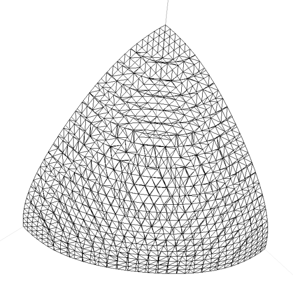
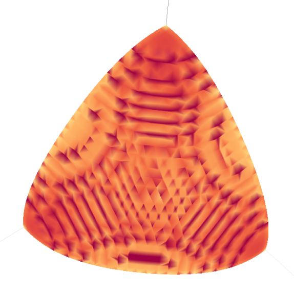
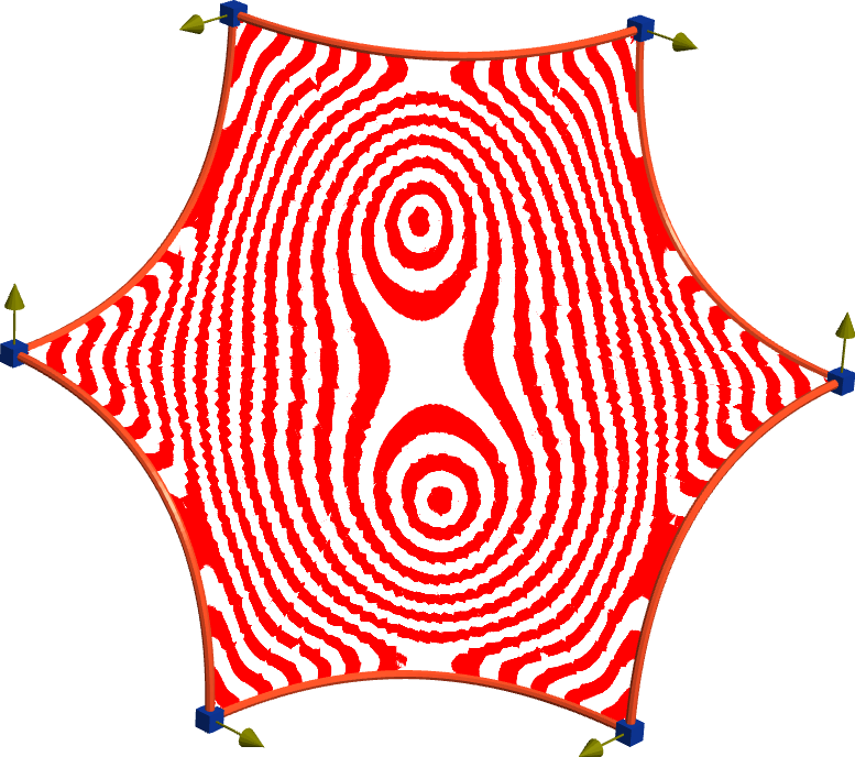
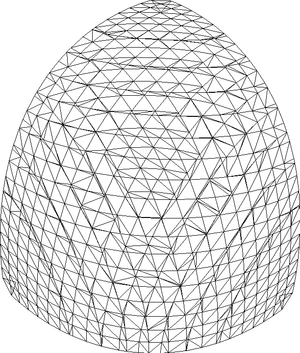
Such meshes, however, often do not have good enough quality to accurately approximate differential surface quantities. In surface analysis, it is often important to use coloring based on normal vectors, various curvatures and other measures to identify potential defects. A mesh directly produced by Marching Cubes (see e.g. Figure 1) is not useful for that purpose.
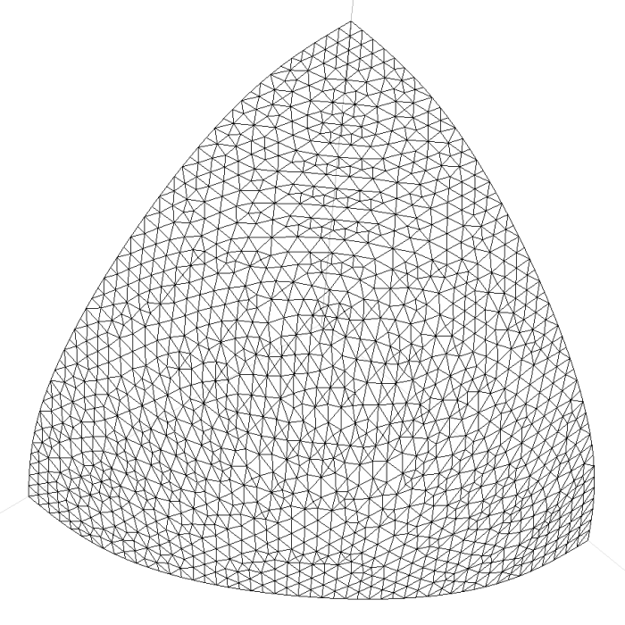
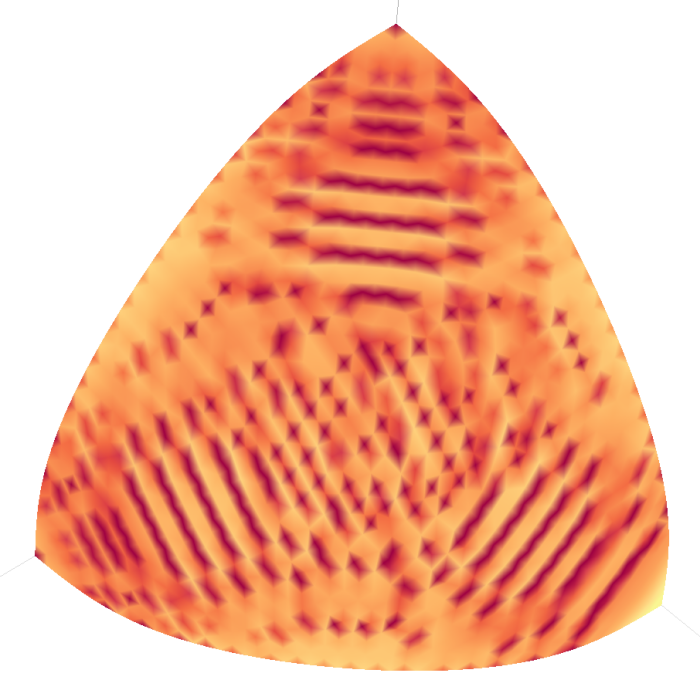
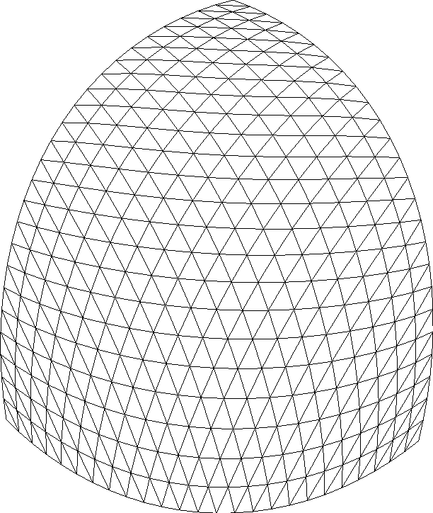
Fairing and edge transformation methods[3] and algorithms based on different principles[4] have been proposed in the literature. However, these often have a high computational overhead, many of them are complicated to implement, and they do not guarantee that the resulting mesh will be free of anisotropic triangles and vertices with unusually high or low valencies. For example, in Figure 2, the mesh was processed by Laplace fairing, which has considerably improved the quality of individual triangles, but the mesh still includes degree 4 or degree 8 nodes where calculating mean curvature becomes inaccurate.
Therefore, our approach is to first create a well-structured mesh topology loosely around the surface, and then project its points onto the implicit surface. In Section 2 we will outline our method, and in Section 3 surface examples will be shown. An assessment of the algorithm will conclude the paper in Section 4.
2 Meshing
Our method works with a space partitioning that divides the implicit isosurface into several multi-sided pieces each containing only a single surface sheet. One such structure is an octree, which we subdivide while there are multiple surface sheets in a cell. However, the algorithm can be used with any convex partitioning which is made of planar cuts (an example will be shown in Subsection 3.2).
First we can create the corner points of the multi-sided surfaces, which will be the basis of the algorithm. For each edge of a cell, if its endpoints are on different sides of the surface, we need to find the intersection point which will be the corner point. Then for each face of the cell, we connect the intersections with an edge, so that we have a boundary loop of the patch.
2.1 Base mesh
Next, a base mesh is created, using an auxiliary parametric surface, which interpolates the corner points and the boundaries. The simplest method is to use a generalized barycentric[5] combination of the corner points over a regular -sided domain:
| (1) |
where , and . are the domain coordinates of the corners of the regular -gon; are the corner points of the surface. This ensures that the edges of the patch will run in the appropriate face dividing the cell from its neighbour.
Alternatively, as the implicit surface can be highly curved, a simple transfinite parametric surface can be used, like the multi-sided Coons patch[6] which is defined by its boundary curves. If those do not have a simple parametric representation, they can be given as dense polylines111As the mesh vertices will be projected onto the surface, the slight error arising from the inexact curves will not meaningfully affect the final result. evaluated via tessellating each implicit boundary curve, which is the intersection of the planar bounding face with the implicit isosurface.
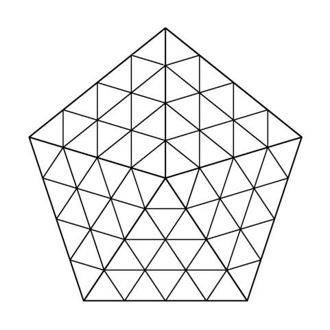
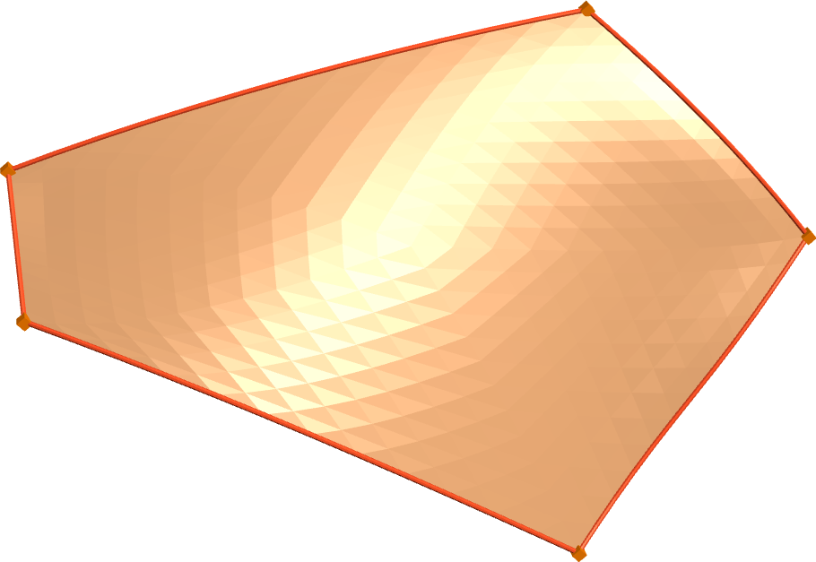
These surfaces can then be elegantly tessellated by dividing the -sided polygonal domain into triangles like in Figure 3.
2.2 Projection
When projecting the points of the mesh onto the isosurface, we must ensure continuous connection to neighbouring patches. For that, we need the points on the edge of the patch to remain on the face of the cell after projection. We also want triangles to change their size relative to each other as few as possible.
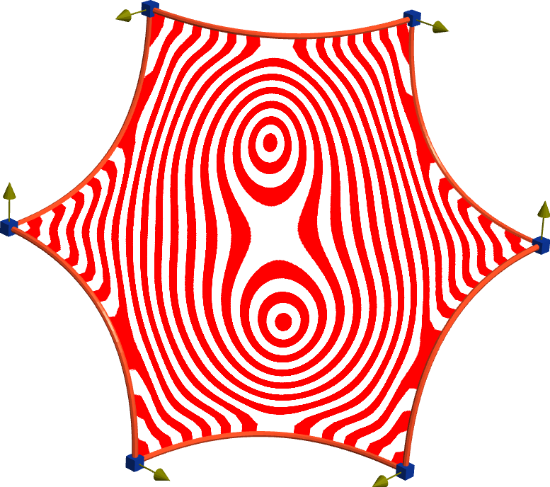
We achieve this by defining a projection direction (a 3-dimensional vector) attribute for each vertex which will prescribe the line, along which the point will be projected. The projection direction is prescribed in the corners of the patch, and is then interpolated along the mesh using barycentric coordinates. In the corners, they need to point in the same direction from the isosurface (e.g. into the positive half-space). See 2-dimensional example in Figure 4.
If the boundary points have to be moved (i.e. we are not using a base patch with exact boundary points), then at corner points the direction shall be set as the direction of the edge of the cell there. This ensures that in edge points the direction is inside the bounding plane, as it is the weighted sum of two edges in that plane (all other barycentric coordinates are zeros there). Thus, the projected points will also remain there.
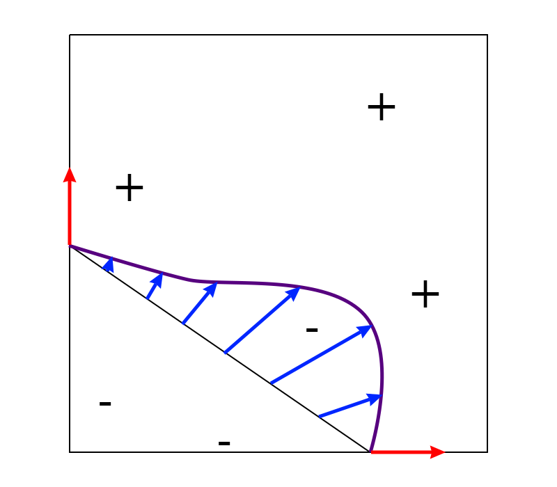
Purple: implicit surface, red: prescribed directions, blue: interpolated directions. Signs denote the sign of the implicit function in that region.
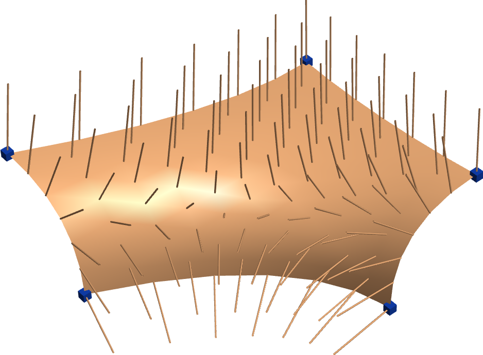
See Figure 5 for a visualization of these direction vectors.
Now we can use ray marching to find the isosurface point for each vertex. By checking the sign of the implicit function in the starting point, we know in which direction the isosurface lays, relative to the interpolated direction. In the end, we replace the mesh positions with the projected positions, getting a mesh representing the piece of the original isosurface inside the cell. Corner points are not moved, and if the boundary curves were already approximated, boundary points stay in place as well.
The above process unfortunately does not guarantee that correct results are obtained. If the isosurface has high curvature variation or large shape artifacts, the resulting mesh might contain abrupt jumps or overlapping triangles. We prevent this by checking if the angle between the ray and the gradient of the surface remains under a prescribed threshold. If not, the resulting mesh is rejected, and we can try to solve the problem by subdividing the cell. This typically indicates, however, that the quality of the implicit surface would not be acceptable.
3 Examples
3.1 Cell patches
Surface patches inside cubic cells can easily be compared, as these can be efficiently tessellated with both Marching Cubes and the proposed algorithm, and they will represent the exact same surface. We show such comparisons in Figures 6, 7 and 8.
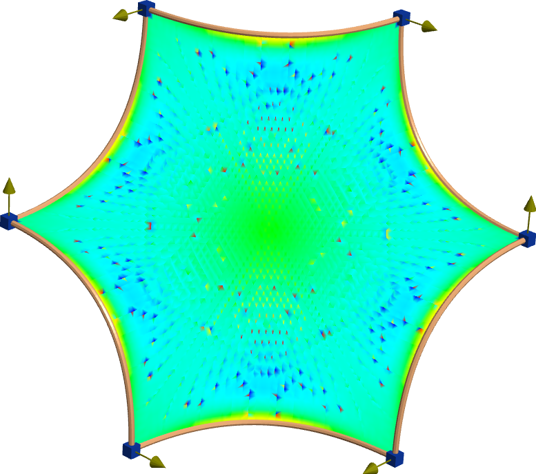
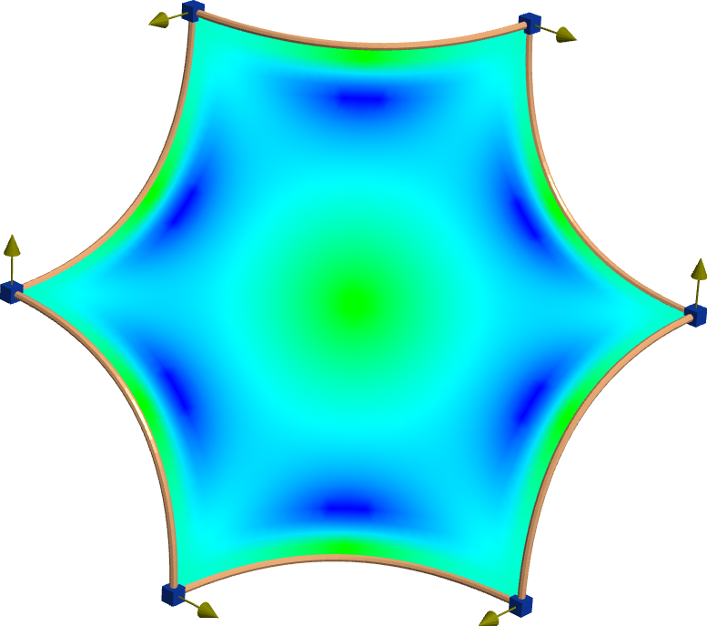
| Marching cubes | Projection | ||
|---|---|---|---|
| Vertices | Time | Vertices | Time |
| 688 | 20ms | 351 | 4ms |
| 1760 | 58ms | 561 | 8ms |
| 3881 | 136ms | 1326 | 14ms |
3.2 General -sided patches
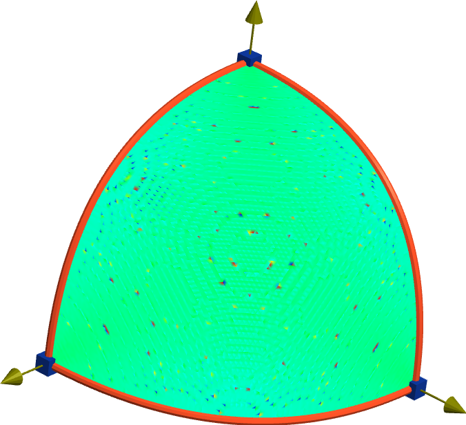
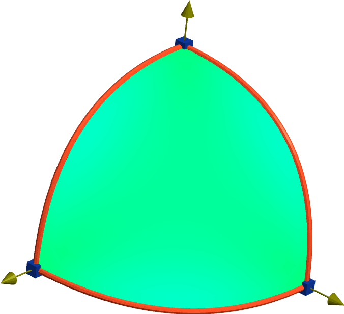
In case of general space partitions bounded by planes, the resulting surface can also be nicely triangulated, as in Figure 9.
Approach to I-patches defined by control polyhedra
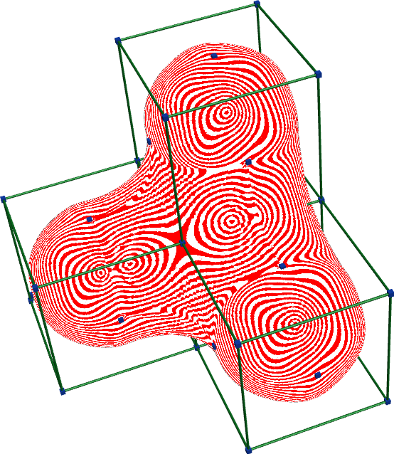
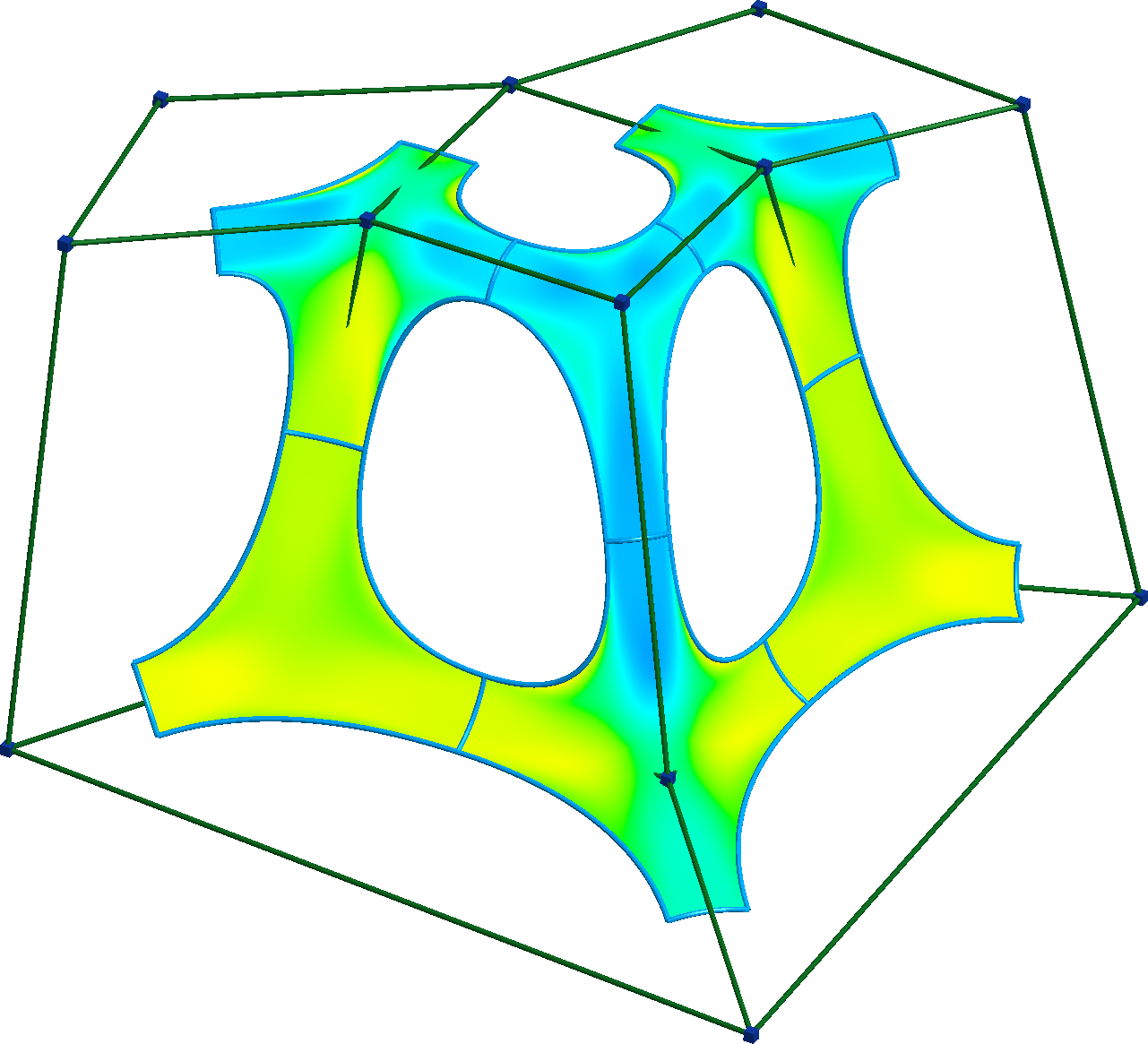
We used a slightly different approach in our recent paper[7] where I-patches[8] are defined based on control polyhedra, so the corner points and boundary curves of the individual patches are known in advance. As a result, the space partitions can also be bounded by nonplanar surfaces, and the boundary curves do not have to be traced. The curves are then used to construct the multi-sided Coons patch, and then we project the points onto the mesh. The images in that paper were generated with this method. An example, compared to Marching Cubes, is shown in Figure 10. The method works even for patches defined inside concave space partitions, for example in the case of the setback vertex blends[9] seen in Figure 11.

4 Conclusion
We have proposed an algorithm for creating good quality meshes for visualizing smooth implicit surfaces. Our method gives more accurate results when approximating differential quantities on the surface, due to the evenly distributed valencies of the mesh vertices. This is an offline algorithm, and compared to Marching Cubes, it requires significantly fewer points to achieve the same level of detail.
However, the algorithm does not necessarily yield correct results. It may be useful future work to provide conditions ensuring a good tessellation.
Acknowledgements
This project has been supported by the Hungarian Scientific Research Fund (OTKA, No. 124727: Modeling general topology free-form surfaces in 3D). The authors thank Tamás Várady for his valuable comments.
References
- [1] William E Lorensen and Harvey E Cline. Marching Cubes: A high resolution 3D surface construction algorithm. SIGGRAPH Comput. Graph., 21(4):163–169, 1987.
- [2] Timothy S Newman and Hong Yi. A survey of the marching cubes algorithm. Computers & Graphics, 30(5):854–879, 2006.
- [3] Carlos A Dietrich, Carlos E Scheidegger, John Schreiner, Joao LD Comba, Luciana P Nedel, and Cláudio T Silva. Edge transformations for improving mesh quality of marching cubes. IEEE Transactions on Visualization and Computer Graphics, 15(1):150–159, 2009.
- [4] Bruno Rodrigues De Araújo, Daniel S Lopes, Pauline Jepp, Joaquim A Jorge, and Brian Wyvill. A survey on implicit surface polygonization. ACM Computing Surveys (CSUR), 47(4):1–39, 2015.
- [5] Michael S Floater. Generalized barycentric coordinates and applications. Acta Numerica, 24:161–214, 2015.
- [6] Péter Salvi. A multi-sided generalization of the Coons patch. In Proceedings of the Workshop on the Advances of Information Technology, pages 110–111, 2020.
- [7] Ágoston Sipos, Tamás Várady, Péter Salvi, and Márton Vaitkus. Multi-sided implicit surfacing with I-patches. Computers & Graphics, 90:29–42, 2020.
- [8] Tamás Várady, Pál Benkő, Géza Kós, and Alyn Rockwood. Implicit surfaces revisited – I-patches. In Geometric Modelling, pages 323–335. Springer, 2001.
- [9] Tamás Várady and Alyn Rockwood. Geometric construction for setback vertex blending. Computer-Aided Design, 29(6):413–425, 1997.