The relative contributions of TWIP and TRIP to strength in fine grained medium-Mn steels
Abstract
A medium Mn steel of composition Fe-4.8Mn-2.8Al-1.5Si-0.51C (wt.%) was processed to obtain two different microstructures representing two different approaches in the hot rolling mill, resulting in equiaxed vs. mixed equiaxed and lamellar microstructures. Both were found to exhibit a simultaneous Twinning Induced Plasticity and Transformation Induced Plasticity (TWIPTRIP) mechanism where deformation twins and -martensite formed independently of twinning with strain. Interrupted tensile tests were conducted in order to investigate the differences in deformation structures between the two microstructures. A constitutive model was used to find that, surprisingly, twinning contributed relatively little to the strength of the alloy, chiefly due to the fine initial slip lengths that then gave rise to relatively little opportunity for work hardening by grain subdivision. Nevertheless, with lower high-cost alloying additions than equivalent Dual Phase steels (2-3 wt% Mn) and greater ductility, medium-Mn TWIPTRIP steels still represent an attractive area for future development.
1 Introduction
Medium Mn steels with Mn contents of 4-12 wt% are seeing a rise in interest as a successor to high Mn (16-30 wt% Mn) TWIP steels, named after the Twinning Induced Plasticity (TWIP) effect. TWIP steels are fully austenitic, have large elongations of 50% and strain hardening rates of up to 3 GPa, resulting in a large amount of energy absorbed upon deformation [1, 2, 3, 4, 5]. However, due to the large Mn content, TWIP steels are unable to be processed using conventional secondary steelmaking processes [6, 7]. Additionally, the large Mn content has resulted in TWIP steels being significantly more expensive than other automotive strip steels [8], e.g. Dual Phase (DP) steels which are currently used in energy absorbing applications [9, 10]. A combination of these factors have led to limited industrial adoption of TWIP steels.
Within the past decade, many medium Mn steels have been developed with tensile properties that exceed those of TWIP steels. By reducing the Mn content, the microstructure of medium Mn steels are duplex (). Depending on the thermomechanical processing history, a myriad of morphologies, phase fractions and distributions of the two phases can be produced. Regarding microstructure and morphology, the two most common microstructures are equiaxed and lamellar [11]. Medium Mn steels with equiaxed microstructures typically have polygonal and evenly distributed austenite and ferrite grains. Lamellar or laminated microstructures have alternating austenite and ferrite lamellae contained within a prior austenite grain. Most medium Mn steels are either equiaxed, lamellar or both [11, 12, 13]. However, medium Mn steels with lamellar microstructures tend to be stronger, due to Hall-Petch strengthening arising from a smaller lamella thickness although some exceptions exist [14], and are less prone to yield point elongation [15, 16]. Nevertheless, due to industrial thermomechanical processing limitations, it is difficult to produce a microstructure that is entirely equiaxed or lamellar. The second medium Mn steel to be produced on an industrial scale by voestalpine in Linz had a mixed lamellar and equiaxed microstructure [17, 18].
In addition to the many types of microstructures that can be produced in medium Mn steels, many different plasticity enhancing mechanisms, on top of dislocation glide, can be activated in the austenite phase. By reducing the Mn content compared to high Mn TWIP steels, the stability of the austenite phase is lowered greatly such that stress-assisted or strain induced martensitic transformation is possible, i.e. the Transformation Induced Plasticity (TRIP) effect. Additionally, if the Stacking Fault Energy (SFE) can be raised into the twinning regime (15-35 mJ m-2) through element partitioning during an Intercritical Annealing (IA) heat treatment, the TWIP effect may also be activated [19, 20]. Medium Mn steels can therefore also be grouped according to their plasticity enhancing mechanism, i.e. TRIP-type or TWIPTRIP-type [21, 12].
Many medium Mn steels have exhibited both TWIP and TRIP behaviour but they often occur in different austenite grains, e.g. coarse austenite deforming via TRIP and fine austenite deforming via TWIP [22, 23, 24]. This means that the austenite grains do not deform homogeneously and such steels often exhibit serrations in the strain hardening curve. Therefore, the combined TWIPTRIP effect, which occurs in a single austenite grain, is of particular interest as it allows for homogeneous deformation, sustained hardening during deformation and elongations in excess of 40% [19, 25, 20, 24, 26, 27]. However, the interplay between TWIP and TRIP can be very different. Lee et al. [19, 28] identified the successive TWIPTRIP effect in a steel with austenite composition Fe-10.3Mn-2.9Al-2.0Si-0.32C. It was found that the austenite phase first formed twins and subsequently strain induced martensite at the twin intersections. This successive TWIPTRIP effect led to a two-stage hardening behaviour where the first stage was twinning dominated and the second stage was transformation dominated. Sohn et. al. [26, 27] seperately indentified a slightly different mechanism where twins and martensite formed concurrently and independently within an austenite grain during deformation. In their steel with austenite composition of Fe-11.5Mn-4.74Al-0.55C, the simultaneous TWIPTRIP effect led to a multi-stage hardening behaviour and an exceptional 77% total elongation.
Between the successive and simultaneous TWIPTRIP mechanisms, the successive mechanism is more widely reported [25, 29, 19, 28] and is also the more commonly accepted mechanism of Strain Induced Martensite (SIM) nucleation and growth in Metastable Austenitic Stainless Steels (MASS) such as 304 and 301 [30, 31, 32]. The steel benefits from a high strain hardening rate ( GPa) because of two powerful plasticity enhancing mechanisms operating after each other. In the simultaneous mechanism, however, the twinning and transformation kinetics appear to be very slow, providing just enough hardening to avoid necking [26]. Nevertheless, it allowed for a very steady engineering stress up to the failure strain of 77%, signifcantly larger than medium Mn steels which exhibit the successive TWPTRIP mechanism (40-50%).
It is still uncertain what factors determine whether the austenite phase deforms via successive or simultaneous TWIPTRIP although factors such as microstructure, SFE and austenite stability are likely to play a large role [33, 34, 20]. Furthermore, the majority of medium Mn steels shown to exhibit the TWIPTRIP effect possess equiaxed microstructures, i.e. polygonal austenite grains. Not much is known how the TWIPTRIP effect occurs in lamellar or mixed microstructures. This study therefore aims to explore the effect of microstructure on the interplay between TWIP and TRIP mechanisms and therefore their relative contributions. This would be achieved by producing two types of microstructures with similar austenite volume fraction and composition and examining how the various deformation structures evolve with strain.
2 Experimental
A steel ingot of dimensions 70 23 23 mm was produced via vacuum arc melting. The bulk composition shown in Table 1 was measured using Inductively Coupled Plasma (ICP) and Inert Gas Fusion (IGF). In order to simulate an industrial reheating cycle, the ingot was homogenised in a vacuum tube furnace at 1250 °C for 2 h and allowed to furnace cool to room temperature. A previous study [35] showed that the abovementioned homogenisation schedule was able to significantly reduce microsegregation in an arc melted ingot. The ingot was then reheated to 1100 °C and rough rolled at the same temperature from 23 to 12 mm thickness in 4 passes and water quenched. The rough rolled ingot was then split along the long axis into two bars via Electric Discharge Machining (EDM). The bars were then reheated to 1000 °C and finish rolled from 12 mm to 1.5 mm thick strip in 5 passes with a finish temperature of 850 °C. The 5 passes were conducted at 50%, 40%, 30%, 30% and 25% thickness reductions with a reheat between each pass. One strip was water quenched immediately after the last pass, while the another strip was cooled to 600 °C and held for 30 min to simulate the coiling process and finally furnace cooled to room temperature. Both strips were then intercritically annealed at 750 °C for 10 min. The final samples produced either by furnace cooling or water quenching will be referred to as FC and WQ respectively. In order to improve strain uniformity along the length of the rolled strip during finish rolling, the rolling speed was gradually increased after each pass to ensure a relatively constant rolling duration and minimise excessive temperature loss from the strip. However, it is acknowledged that under laboratory conditions, it is very difficult to guarantee precise temperatures and the degree of deformation across the length of each strip as well as between strips since the finish rolling of FC and WQ conditions were conducted separately.
Tensile samples with gauge dimensions 19 3 1.5 mm were machined from both strips via EDM, such that the tensile direction was parallel to the rolling direction. Tensile testing was subsequently conducted on an Instron load frame with a 30 kN load cell at a nominal strain rate of s-1.
Samples for Electron Backscattered Diffraction (EBSD) were mechanically ground and polished with an OPU polishing suspension. Samples for Transmission Electron Microscopy (TEM) and Transmission Kikuchi Diffraction (TKD) were prepared by mechanically thinning a 3 mm disk of material to below 90 µm in thickness and subsequently electrolytic polished using a twin-jet electropolisher with a solution containing 5% perchloric acid, 35% butyl-alcohol and 60% methanol at a temperature of °C.
EBSD was conducted on a Zeiss Sigma FEG-SEM equipped with a Bruker EBSD detector. TEM and Energy Dispersive Spectroscopy (TEM-EDS) was conducted on on a JEOL JEM-F200 operated at an accelerating voltage of 200 kV. Transmission Kikuchi Diffraction (TKD) was conducted on a JEOL 7900 FEG-SEM.
3 Results
Fe Mn Al Si C† N† P S† Bal 4.77 2.75 1.51 0.505 0.003 0.005 0.002
3.1 Tensile properties
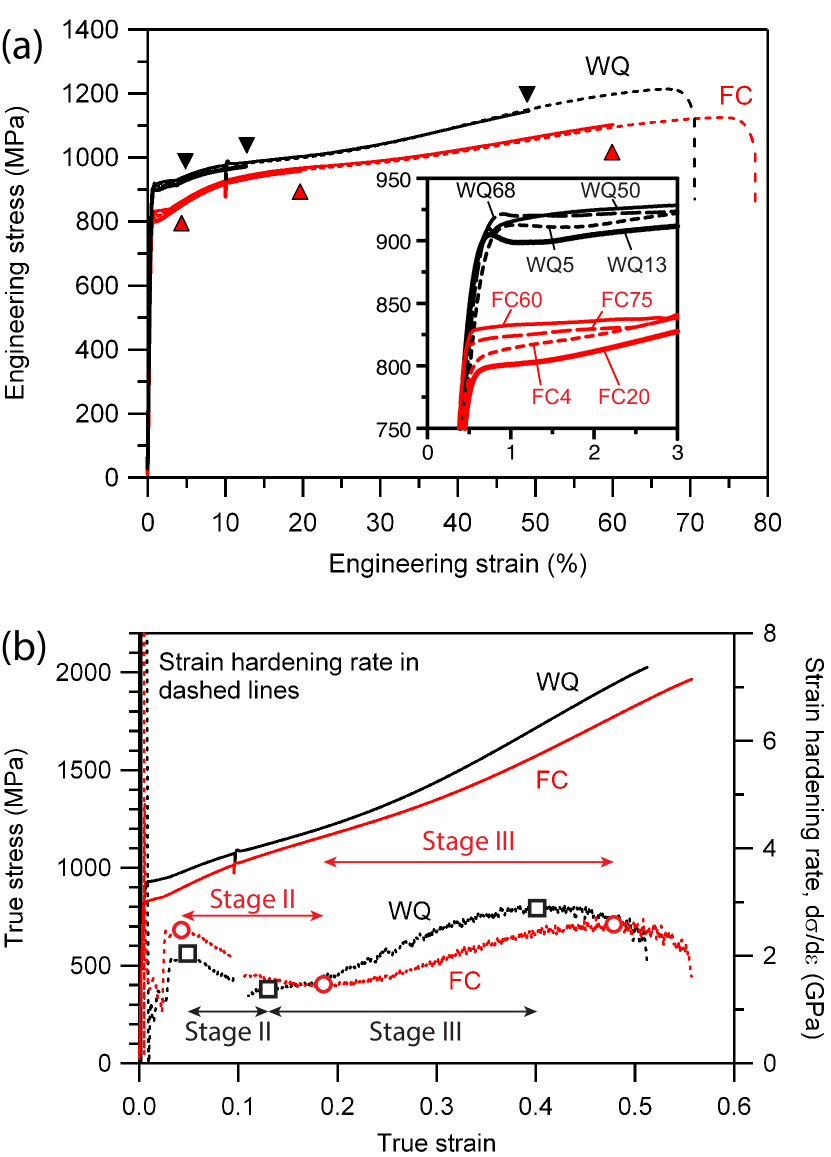
The tensile behaviour of the FC and WQ conditions are shown in Figure 1 and the tensile properties are summarised in Table 2. Due to the small widths and thicknesses of the tensile samples, associated with the use of 400 g scale laboratory melts, the uncertainty budgets are greater than in full scale standards-certified tests [39], approximately for the yield stress. As a result, the yield and tensile strengths in Table 2 are given to two significant figures. The average yield strength could be determined from the various interrupted tensile samples; for the FC and WQ conditions, the average yield strengths were MPa (range 795 – 829 MPa, n=4) and MPa (range 894 – 918 MPa, n=4) respectively, where n is the number of test samples. While there may be some variation in yield strengths due to the relative errors in the measurement of the tensile gauge cross section, Figure 1a showed that all tensile samples had very similar deformation behaviour, giving confidence in the uniformity of composition, strain and temperaure during finish rolling across the length of the rolled strip.
From Figure 1a, it can be seen that both FC and WQ steels have very high strengths (800 MPa) and exceptional ductility (70%). The WQ sample had a higher yield and tensile strength but the FC sample had a slightly longer elongation. The inset in Figure 1a showed that both FC and WQ samples had a short yield point elongation of approximately 2% strain.
When the Strain Hardening Rate (SHR) was obtained by differentiating the true stress-strain curve, it can be seen that they possessed a very similar shape, similar to many medium Mn steels [19, 28, 40] and MASS [31, 41, 42, 43] that exhibit the successive TWIPTRIP effect. Three hardening stages can be identified. At stage I, i.e. the onset of plastic deformation, both SHR curves showed a rapid decrease, reaching a local minima at approximately 0.02 true strain before increasing rapidly to the first peak between 0.04 and 0.05 true strain. At stage II, the SHR then decreases from the first peak to a saddle point and at stage III it rises again slowly to the second peak. While the shape of the SHR curves may be similar, the strain at which the first peak, saddle point and second peaks occur as well as its value differ slightly between the FC and the WQ steel. To investigate the microstructural evolution at these three unique points (first peak, saddle point and second peak), interrupted tensile tests were conducted up to the corresponding strains for the FC and WQ steel. The as-annealed and interrupted tensile samples are henceforth named FC0, FC4, FC20, FC60 for the FC steel and WQ0, WQ5, WQ13, WQ50 for the WQ steel where the digits represent the engineering strain (not true strain) to which they were tested, rounded to the nearest percent.
| E | UTS | MPa% | |||
|---|---|---|---|---|---|
| (GPa) | (MPa) | (MPa) | (%) | () | |
| FC | 210 | 820 | 1100 | 78 | 86 |
| WQ | 190 | 900 | 1200 | 71 | 85 |
3.2 Microstructure
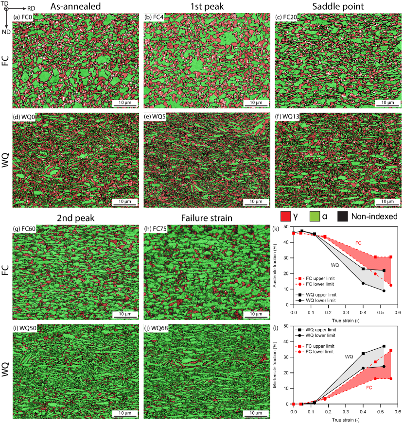
EBSD Image Quality and Phase Maps (IQ+PM) of the FC and WQ steels at varying strain are shown in Figure 2. In the as-annealed condition, FC0 showed a largely equiaxed microstructure (Figure 2a). It was likely that the cementite in the pearlite matrix globularised and transformed into austenite during the IA, while WQ0 adopted a mixed equiaxed lamellar microstructure. The lamellar regions arose when austenite nucleated in between martensite laths, while the equiaxed regions formed due to some degree of recrystallisation of martensite, predominantly around the PAGBs.
With increasing strain, it was observed that the austenite fraction began to decrease after the first peak, indicating that the TRIP effect was operative in both FC and WQ steels. However, due to the increasing Non-Indexed (NI) fraction at higher strain levels, there was some uncertainty in the calculated martensite fraction, which indexes as BCC in EBSD. It is acknowledged that the NI regions are typically either martensite or deformed austenite. Therefore, an upper and lower limit was established in Figures 2k-l where the upper martensite limit was obtained if the entire NI fraction was treated as martensite and the lower martensite limit was obtained if the entire NI fraction was treated as austenite and vice versa for the austenite upper and lower limits. In Figure 2k, it appears that the austenite fraction increased slightly between WQ0 and WQ5. This was likely due to a small variation in microstructure between the tensile specimens as austenite fraction cannot increase with strain.
Between the as-annealed condition and the first peak, there was no transformation in both FC and WQ steels, suggesting that an incubation strain was needed for the TRIP effect. Subsequently, with increasing strain, the martensite fraction in the WQ steel increased at a higher rate compared to the FC steel with a larger final fraction at the failure strain. In the FC steel, both ferrite and austenite grains were observed to elongate in the tensile direction while in the WQ steel, the lamellar regions were also observed to elongate but additially rotating and orienting themselves parallel to the tensile direction at the failure strain.
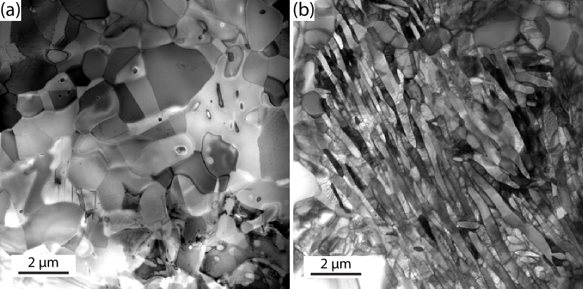
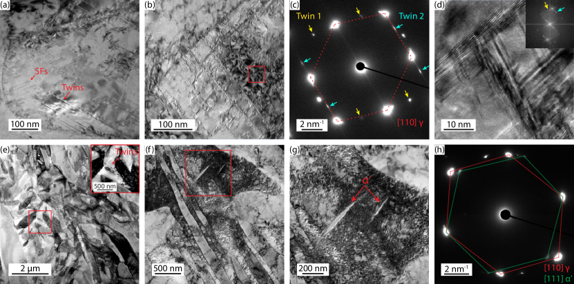
While EBSD was able to provide macroscopic insights into the microstructural evolution, it was necessary to probe the finer deformation structures using TEM. Figure 3 shows the microstructure of the FC and WQ steel in the as-annealed condition under STEM-BF. The as-annealed FC microstructure showed an equiaxed microstructure with a low dislocation density. On the other hand, the as-annealed WQ microstructure showed a lamellar microstructure with average lamella width of 290 nm. A relatively larger number of dislocations were observed in the WQ microstructure. Han et al. [14] also found that the ferrite phase in lamellar type microstructures had a higher dislocation density than equiaxed ferrite due to the lack of recrystallisation during IA. While the FC microstructure was not obtained via cold rolling and recrystallising, the multiple phase transformations during coiling, furnace cooling and IA were likely able to eliminate any residual dislocation density after hot rolling.
3.2.1 Stage I: zero strain to first peak
At stage I, there was no transformation as shown in Figure 2k. From Figure 4, it was observed that dislocation multiplication was occuring in the austenite and ferrite phases in both the FC and WQ conditions. Twinning in both conditions was also very limited. In FC4, multiple Stacking Faults (SFs) were observed growing from austenite and annealing twin boundaries. In WQ5, SFs were also observed but only in the more globular austenite grains. In the lamellar grains however, no SFs were observed. Instead, dislocations were emitted from the interphase boundaries and also seen to be piling up across the width of certain lamellar grains. The higher density of SFs in FC4 may also explain why the SHR at the first peak was higher than WQ5.
In many fine grained equiaxed medium Mn steels, the first peak is the result of yield point elongation [28, 29]. Sun et al. [15] have shown that this was because of a rapid dislocation generation from the large amount of interfaces in a relatively dislocation free microstructure. Lamellar microstructures typically exhibit continuous yielding due to a higher dislocation density within the lamellar grains, as seen in Figure 3b. However, because WQ was a mixed microstructure, combining both equiaxed and lamellar regions, a short yield point elongation was still present.
3.2.2 Stage II: first peak to saddle point
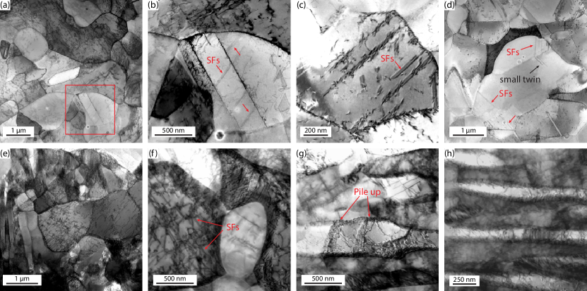
Figure 5 shows the microstructures of FC20 and WQ13 at the SHR saddle point. In FC20, some austenite grains were observed to have one set of twins, while others were observed to have two. Figure 5a shows an austenite grain with twins growing out from the grain boundary while stacking faults were growing in the other twinning direction. The SFs appear to have either nucleated from the grain boundary or from the first twins. In another austenite grain in FC20 as shown in Figures 5b-c, two twinning systems were clearly operating as also shown in the diffraction pattern where two sets of twinning spots were observed. According to the successive TWIPTRIP mechanism described by Lee et al. [19, 44], -martensite at twin intersections should be observed at this strain. However, additional diffration spots associated with martensite transformation were not observed at the twin intersections in FC20. High Resolution TEM (HR-TEM) of the twin intersections also showed no martensite at the twin intersections.
In WQ13, there was very limited twinning compared to FC20. In Figure 5e, only a small twinned region could be found and was not located in a lamellar region. In Figures 5f-g, several thin laths of martensite were found in an austenite grain adjacent to a lamellar region. The diffraction pattern in Figure 5h showed that the martensite laths had a Kurdjumov-Sachs orientation relationship (KS-OR) with the parent austenite. Thin martensite laths were also observed by Lee et al. [40] in a lamellar medium Mn steel.
3.2.3 Stage III: saddle point to second peak
At the second SHR peak, the TEM micrographs of FC60 and WQ50 are shown in Figure 6. In FC60, many twinned austenite grains could be observed such as the one shown in Figure 6a. With increased magnification. Much finer but shorter twins were observed within the grain interior (Figure 6b) and when the magnification was increased further, several short twins from the second twinning system could be observed (Figure 6c). This suggests that twinning continued to occur even up to 60% strain in the FC steel. In another austenite grain as shown in Figure 6d, twin thicknening was observed which has often been found in TWIP steels at large strains [45] and was also observed by Sohn et al. [26] in a medium Mn steel.
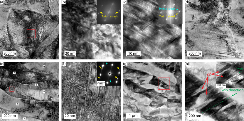
In WQ50, a large number of twinned lamellar austenite grains were observed. This suggests that in WQ, twinning was more active in stage III compared to stage II. Figure 6a shows a lamellar austenite grain with twins that grew across the grain. Further magnification revealed secondary twins at the tip of the lamellar grain. However, the diffraction pattern from the tip still showed that there was no -martensite at the twin intersections. Nevertheless, in another grain (Figures 6g-h), martensite laths were observed growing from the grain boundary across a twinned lamellar austenite grain in the same direction as the twins.
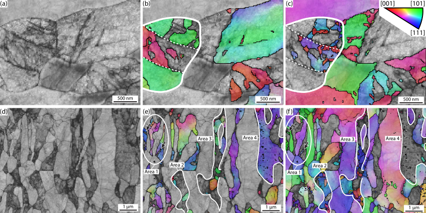
While TEM has effectively revealed the twinned structures in both FC and WQ steels, it was difficult to identify martensitic regions. For this reason, TKD was conducted on the TEM foils from FC60 and WQ50. The resulting data are shown in Figure 7. In the FC60 sample (Figures 7a-c), a deformed equiaxed austenite grain with a curved annealing twin (outlined in white) could be observed from the Band Contrast (BC) and FCC IPF-Z maps. From the BCC IPF-Z map (Figure 7c), BCC regions were observed within the outlined austenite grain. These BCC grains were observed to be within of the KS-OR with the parent austenite grain and were therefore different variants of -martensite. These blocky -martensite grains appear to have first nucleated from the austenite grain boundaries and then from each other, suggesting that -martensite growth was limited and nucleation may have occured continuously with increasing strain. The limited growth may explain why size of the blocky -martensite grains remained very small. However, it cannot be said that the -martensite observed in Figure 7 only formed during stage III, it is likely that some -martensite also formed during stage II.
In the WQ50 sample (Figures 7d-f), the austenite grains before transformation can be identified as the dark grey regions, i.e. more deformed regions in the BC map (Figure 7d). This is also confirmed in Figure 7e where the untransformed austenite lie within the dark grey regions. In Figures 7e-f, four areas of interest are highlighted. In area 1, the arrows point to -martensite grains with a lath morphology which were observed growing across austenite lamellae as observed in WQ13 (Figures 5f-h). However, this morphology was an exception rather than the rule as similar lath martensite morphologies were not commonly observed elsewhere. It is also worth noting that the three austenite lamellae contained in area 1 remained largely untransformed even up to 50% strain. In area 2, the outlined region was likely a globular prior austenite grain but was elongated at 50% strain. The prior austenite grain was mostly transformed with only a few pockets of austenite left. In the BCC IPF-Z map in Figure 7f, several small martensite grains were observed at the prior austenite grain boundary in a similar manner as described in FC60. However, the prior austenite grain was mostly dominated by a single martensite grain with direction out of the page. In area 3, the outlined prior austenite grain was similarly partially transformed to martensite. In the more bulbous region near the bottom left, a single martensite grain with direction out of the page also dominated the region. However, at the bottom tip and along the length of the lamellar grain, the austenite grain transformed into relatively equally sized submicron martensite grains. Finally, in area 4, the untransformed austenite grain contained several extremely fine intragranular martensite grains. These martensite grains were significantly finer and do not appear to have nucleated from a grain boundary in the same manner as in the aforementioned three areas. It is therefore possible that these fine martensite grains are of the twin-twin intersection variety which forms in the successive TWIPTRIP mechanism.
Finally, beyond stage III, comparing the EBSD phase maps in Figures 2g-l, the austenite phase still continued to transform to martensite. However, the strain region beyond stage III is characterised by decreasing SHR (Figure 1b), suggesting that both twin and martensite fractions were both approaching saturation until both steels failed by necking, i.e. .
3.3 Composition
The composition of austenite and ferrite in both FC and WQ steels were measured using TEM-EDS. The results are shown in Table 3. The C content in austenite was determined by using the lever rule, assuming negligible C solubility in ferrite. It should be noted that the bulk composition as measured by TEM-EDS, i.e. where is the Mn, Al or Si content and is the volume fraction of phase , may not be the same as the bulk composition as measured using ICP. The difference may be attributed to the limitations of quantitative TEM-EDS. However, the resolution of TEM-EDS was needed to probe the compositions of the fine grained microstructures in the FC and WQ samples. The SFE was calculated according to the method proposed by Sun et al. [25]. Md30, defined as the temperature where half of the austenite transforms to martensite at a strain of 30% was calculated according to the following equation[46, 47]:
| (1) |
where compositions are given in mass % and is the austenite grain size in µm. A higher Md30 indicates lower austenite stability against strain induced martensitic transformation and vice versa. The Ms temperature, defined as the temperature where athermal martensite begins to form upon rapid cooling from austenite, was calculated according to the following equation [48]:
| (2) |
A higher Ms indicates lower austenite stability against athermal martensitic transformation and vice versa. Both Md30 and Ms have been used to qualitatively determine the stability of austenite against strain induced martensitic transformation.
| Mn | Al | Si | C† | grain | SFE | Ms | Md30 | ||
|---|---|---|---|---|---|---|---|---|---|
| (µm) | (mJ m-2) | ( °C) | ( °C) | ||||||
| Bulk (ICP) | 4.77 | 2.75 | 1.41 | 0.505 | - | - | - | - | - |
| FC0 | 8.40 (0.38) | 1.07 (0.17) | 1.00 (0.11) | 1.10 | 0.46 | 1.5 | 34 | -179 | -17 |
| WQ0 | 7.30 (0.60) | 1.80 (0.10) | 1.00 (0.11) | 1.07 | 0.47 | 1.2 | 31 | -133 | 5 |
| 0.3* | 31 | -150 | -1 | ||||||
| FC0 | 3.81 (0.10) | 2.46 (0.04) | 1.46 (0.05) | 0 | 0.54 | 3.0 | - | - | - |
| WQ0 | 3.92 (0.05) | 2.25 (0.12) | 1.37 (0.07) | 0 | 0.53 | 1.3 | - | - | - |
Comparing the austenite compositions between the FC and WQ states in Table 3, it can be seen that the FC condition had a slightly higher Mn content while the other elements remained relatively equal. This may be attributed to the additional coiling and furnace cooling steps during the processing of the FC condition which provided additional time for Mn to partition out of ferrite and into the cementite phase. During the IA step, the cementite then globularised and transformed into austenite with an enriched Mn content compared to the WQ condition. The difference in Mn content resulted in a slightly higher SFE and lower Md30 and Ms for FC.
The SFE of FC and WQ steels were both within the predicted twinning regime of TWIP steels [1] and also medium Mn steels [20]. On the other hand, because of the large C content in both steels ( wt%), the Md30 and Ms temperatures were very low, suggesting that the austenite was very stable. In medium Mn steels, Lee et al. [19] demonstrated that it was possible to overstabilise the austenite phase such that the TRIP effect no longer becomes operative. While the TRIP effect was clearly observed in both FC and WQ, the high austenite stability would certainly have an effect on the nucleation and growth of -martensite grains.
3.4 Modified constitutive model
After examining the microstructural evolution with strain using EBSD, TEM and TKD, it is evident that it was the simultaneous, rather than the successive TWIPTRIP mechanism that was active in both FC and WQ conditions as -martensite grains were not observed at twin intersections and have mostly nucleated at austenite grain boundaries. Microstructural examination also showed that the evolution of deformation structures such as twins and -martensite were very different between FC and WQ conditions. The different twinning kinetics theoretically should have resulted in a clear difference in strain hardening profiles between the FC and WQ conditions. However, from Figure 1b, the strain hardening rate curves between FC and WQ conditions showed a very similar profile.
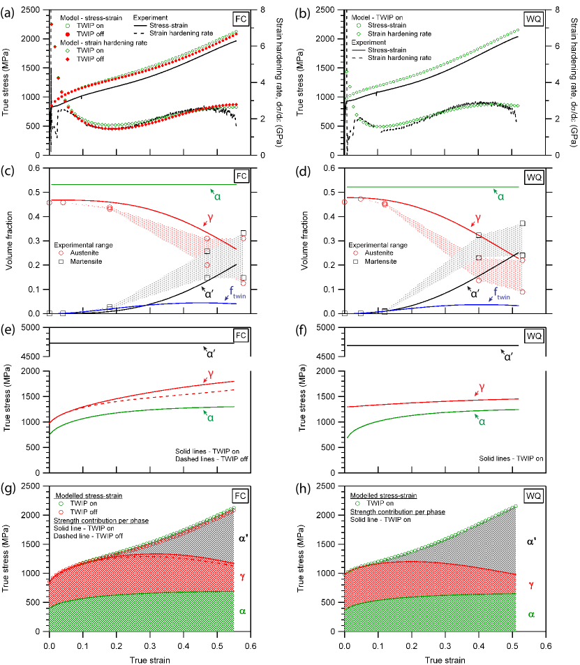
In order to reconcile the seemingly conflicting observations between the tensile properties and microstructure evolution, a constitutive model developed by Lee et al. [19, 28, 36] was used to determine if the tensile properties in Figure 1 could be reproduced given the microstructural data from Figures 2-7 and vice versa. Since the constitutive model was initially developed for medium Mn steels that exhibited the successive TWIPTRIP mechanisms, two key changes were made in order to accomodate the simultaneous TWIPTRIP mechanism. Firstly, equations responsible for the evolution of martensite fraction with strain were replaced with a single Avrami equation [49, 50, 51] which also effectively uncouples the dependence of TRIP on TWIP. Secondly, following the findings of Latypov et al. [37], the strength of the -martensite phase was approximated to be constant with strain. The results from the modified constitutive model are shown in Figure 8.
From Figure 8a, a good agreement between the model and experimental stress-strain and SHR curves was observed for the FC condition. A slight overprediction was observed in the modelled stress-strain curve but can be attributed to the model assuming continuous yielding and not accounting for the slight yield point elongation in the FC condition. From Figure 8c, the predicted austenite and -martensite phase fractions were shown to be in reasonable agreement with the experimental ranges as determined using EBSD in Figure 2. This largely confirms the validity of the modified constitutive model for modelling the simultaneous TWPTRIP mechanism in equiaxed-type microstructures.
However, the same model did not work as well when applied to the WQ condition. In Figure 8b the model appears to show a good fit with the SHR curve, however the predicted -martensite fraction fell short of the experimentally determined range at a true strain of 0.4 in Figure 8d. This was largely attributed to the mixed equiaxed and lamellar grain morphology in the WQ condition which might have led to a more complex strain partitioning mechanism that might not be best represented with the current equations. Nevertheless, the model was able to reasonably predict the initial and final martensite fractions in the WQ condition.
Since TWIP and TRIP mechanisms have been uncoupled in the modified constitutive model, it is possible to model the plastic response without the TWIP effect. In Figure 8a, both modelled stress-strain and SHR curves are shown with the TWIP effect turned on or off. Remarkably, there was no significant loss in strain hardening even with the TWIP effect turned off. In the WQ condition (Figure 8b), there was almost no difference whether the TWIP effect was turned on or off. Therefore the modelled stress-strain and SHR curves with TWIP off were not shown in Figure 8b.
The component stress-strain curves in the FC and WQ conditions are shown in Figures 8e-f respectively. In the FC condition, the TWIP effect was observed to strengthen the austenite phase by 167 MPa at the failure strain. However, this strength was reduced to only 44 MPa when the loss of austenite volume fraction to -martensite transformation was taken into account as seen in Figure 8g. From Figure 8f, the austenite phase was not observed to strain harden significantly in the WQ condition, largely due to the close competiton between dislocation multiplication and annihilation arising from the short lamella thickness. The lack of any difference in strength between the TWIP on and off conditions in WQ was likely due to the severe reduction in the dislocation storage rate in the austenite grains due to the already very fine lamella widths [52]. Therefore, further refinement of the grain size through the dynamic Hall-Petch effect [1, 5] due to twinning proved to be ineffective in improving the strength of the austenite phase in the WQ condition.
By multiplying the component strength by the respective volume fraction of each phase, the cumulative contribution to global strength from each phase with strain can be obtained and is shown in Figures 8g-h. It can be seen that the strength contribution from the TWIP effect is dwarfed by the TRIP effect. The strength from the -martensite phase contributes to nearly 50% of the UTS in the FC condition and more than 50% of the UTS in the WQ condition.
4 Discussion
4.1 -martensite nucleation and growth
In order to attain a sustained high SHR and large elongations in TRIP-assisted steels, it is necessary to continuously form fine -martensite in a steady manner over a wide strain range [53, 54]. A common strategy is to create a spread in austenite stability via grain size distribution [53], inhomogeneous Mn composition [55] or texture [33]. This leads to a spectral TRIP [53] or discontinous TRIP effect [55, 33, 56] where transformation begins and ends with the least and the most stable austenite grains respectively.
In both FC and WQ conditions, the austenite phase was chemically very stable against -martensitic transformation due to the high Mn and C content (Table 3). Chatterjee et al. [57] showed that with such high C contents, formation of Strain-Induced Martensite (SIM) would be highly improbable. However, an applied stress can provide an additional mechanical driving force, , for Stress-Assisted Martensite (SAM) transformation [58, 59]. In medium Mn steels, it is known that strain and therefore stress localises at the interphase boundaries during deformation due to the strength mismatch between austenite, ferrite and -martensite [44]. The high stress localisation was likely to have been able to provide a sufficiently high mechanical driving force for SAM to nucleate at austenite grain boundaries as observed in Figures 5, 6 and 7. Grain boundary SAM nucleation was also observed by Yen et al. [60] in a medium Mn steel with a submicron grain size. The stress-assisted nature of -martensite nucleation may explain why an incubation strain was observed (Figure 2l) as it would be necessary to build up a critical local stress at the austenite grain boundaries. However, the stress field at the grain boundary would decay rapidly towards the interior of the parent austenite grain and the driving force for SAM transformation would similarly diminish. The highly local stress concentration may explain why the -martensite grains in both FC and WQ were very small as -martensite cannot grow past the stress field. With additional deformation, -martensite grains with favourable orientations with stress will grow (areas 2 and 3 in Figure 7), whereas repeated nucleation of -martensite nucleating on top of each other will occur (Figures 7b-c). The phenomenon of -martensite only being able to nucleate and grow within local stress concentrations keeps the -martensite grains small and greatly extends the strain regime where TRIP occurs.
4.2 Effects of microstructure on TWIP and TRIP
The effects of grain size on twinning and martensitic transformation in austenite are well studied. In TWIP steels, there is an impression that grain size reduction generally increases the twinning stress [1]. However, in many studies, reducing the grain size to 1-5 µm does not appear to negatively affect tensile properties and elongation, although it is acknowledged that the twinning stress was increased [61, 62]. From Table 3, the grain size, measured as the equivalent circle diameter, of FC and WQ conditions were not significantly different. However, from Figures 5 and 6 it was observed that extensive twinning occured in stage II and III for FC but mostly in stage III for WQ. In WQ, twins were observed to propagate across the width of the lamellar grains (Figures 6e-h), implying that the lamellar width (approximately 300 nm) should be considered rather than the equivalent circle diameter. Since the austenite lamellar width in the WQ condition was significantly finer than that of the equiaxed grain diameter in FC, the twinning stress in the WQ condition would be much higher and would explain why twinning in lamellar austenite grains was delayed to a later stage compared to equiaxed austenite grains.
In TRIP-assisted steels, it is well known that a decreasing grain size has a strong mechanical stabilisation effect on austenite, inhibiting the formation of -martensite [63, 48, 26]. Additionally, blocky or equiaxed austenite is generally less stable than film or lamellar austenite in medium Mn steels [64, 65]. Therefore, it should follow that the WQ samples would form less -martensite than the FC samples at a similar strain since the lamellar width of the WQ samples was much finer than the grain size in the FC samples. However, from Figure 2l, there was more -martensite in the WQ sample than in the FC sample at failure.
In this alloy, the austenite phase of both FC and WQ conditions were chemically very stable, dominating the mechanical stability term due to grain size refinement in Equation 2, as seen in Table 3. The effect of relative grain size difference on austenite stability between the equiaxed grain diameter in FC samples and the lamella grain width in WQ samples were therefore not expected to be significant. However, -martensite nucleation was shown to be restricted to the austenite grain boundaries where there is a local concentration of stress. In the WQ samples, the lamellar grain morphology has a larger grain boundary area to volume ratio and therefore able to provide a larger number of nucleation sites for -martensite to form. Therefore, it was likely that -martensite was able to nucleate more easily in the WQ samples, resulting in a higher -martensite fraction at failure. However, it is acknowledged that a simple explanation cannot fully capture the complexity of -martensitic transformation in WQ. In Figures 7d-f, the fine austenite lamella in Area 1 and a wide lamellar austenite grain in Area 4 had different surface area to volume ratios yet both remained largely untransformed, suggesting that other effects such as texture, Schmid factors and stress shielding were possibly also involved [33, 65, 64, 66]. Nevertheless, in this alloy with a very high austenite stability where the formation of -martensite was nucleation-limited, grain boundary area to volume ratio would have certainly played a significant role among the other factors known to contribute to -martensite transformation.
4.3 Strain hardening behaviour and constitutive modelling
Perhaps the most striking observation from the modified constitutive model in Figure 8 was the lack of strengthening contribution from the TWIP effect, especially in the WQ condition. Through the original constitutive model developed for successive TWIPTRIP medium Mn steel, Lee and De Cooman [19] showed that the TWIP effect was less effective in small austenite grains and concluded that strengthening from the TRIP effect was more pronounced compared to the TWIP effect. In this study, a similar conclusion was reached for the FC steel with an equiaxed microstructure. However, this study extends the concept to include the simultaneous TWIPTRIP mechanism and for lamellar microstructures which showed a nearly complete lack of contribution to strengthening from the TWIP effect.
Given the lack of strengthening from the TWIP effect, it is therefore unsurprising that the observed differences in twinning kinetics in FC and WQ conditions did not result in a significant difference in the strain hardening behaviour. Instead, the strain hardening behaviour was dominated by the TRIP effect. Furthermore, since both FC and WQ conditions were found to share a similar -martensite nucleation and growth mechanism, it is reasonable to expect the strain hardening profiles to be very similar.
Since the TWIP effect does little in terms of strength for medium Mn steels, it is probably better to not pursue the TWIPTRIP effect in alloy design. In order to enable the TWIPTRIP effect, a relatively high SFE and austenite stability is needed [20]. This is enabled by a combination of either low Mn and high C (current alloy), or high Mn and low C. If the TWIP effect can be forgone during alloy design, it would be possible to enable low to medium Mn and low C (3-6 wt% Mn, 0.05-0.2 wt% C) compositions that exhibit the TRIP effect only. Such low Mn, low C compositions have been increasingly termed lean medium Mn steels [67], and are desirable in terms of lower segregation after casting [35], better weldability [68], processability, etc. However, it is worth noting that while the TWIP effect does little for TWIPTRIP-type medium Mn steels, the tensile properties still tend to be better in terms of elongation than in pure TRIP-type medium Mn steels [19, 26, 27, 69]. The higher Mn and C contents necessary for the TWIPTRIP effect also stabilises the austenite phase and prolongs the TRIP effect to significantly higher strains. Therefore, the alloy chemistry surrounding TWIPTRIP-type medium Mn steels is still worth further study, although less focus might be given to the TWIP effect. It may also be of research interest to determine if the TWIP effect may have other benefits in terms of ductility or performance at high strain rates.
5 Conclusion
The effects of microstructure on the TWIPTRIP mechanism were examined in a 5Mn-0.5C type medium Mn steel in two conditions representing different processing strategies in the steel mill. In the first condition, furnace cooling after hot rolling was employed (FC), as in a coiler; and in the other, water quenching (WQ) on the run-out bed. Both were then intercritically annealed, as on a continuous annealing line. These processing strategies produced steels with similar initial austenite compositions and phase fractions but with equiaxed vs mixed equiaxedlamellar microstructures, respectively. The main findings are:
-
1.
Both FC and WQ conditions showed superior mechanical properties compared to TWIP and DP steels, and the simultaneous TWIPTRIP plasticity enhancing mechanism was identified to be operative in both conditions regardless of microstructural form.
-
2.
A novel -martensite nucleation and growth mechanism in high C austenite was proposed. Stress-assisted -martensite was able to nucleate at the austenite grain boundaries due to the high stress concentration during deformation. The -martensite is unable to grow beyond the stress field into the parent austenite grain due to the high chemical stability and therefore remains small. Therefore, the continuous formation and slow growth of -martensite grains greatly extends the strain regime where TRIP is operative and allows for large elongations to failure.
-
3.
The shorter austenite lamella width in the WQ samples compared to the austenite grain diameter in the FC samples resulted in a shorter mean free path for twinning. This raised the critical twinning stress such that extensive twinning was only observed at higher strains in the WQ sample.
-
4.
A modified constitutive model was developed and found to have a good fit with the experimental data. The model also showed that the TWIP effect did not provide significant strengthening in the FC condition and almost no strengthening in the WQ condition. The lack of strengthening from the TWIP effect was attributed to the extremely fine slip length in the austenite phase, especially in WQ condition where the lamella thickness was in the submicron regime.
5.1 Acknowledgements
TWJK would like to thank A*STAR, Singapore for a studentship. PG would like to acknowledge funding from SUSTAIN Future Steel Manufacturing Research Hub (EP/S018107/1). DD’s work in the early stages of this project was funded by EPSRC (EP/L025213/1) and he also holds a Royal Society Industry Fellowship.
6 Appendix
To model the simultaneous TWIPTRIP effect in the FC and WQ conditions, we follow the constitutive modelling work of Lee et al. [19, 28, 36] and Latypov et al. [37]. This work similarly applies the iso-work assumption to model the strain partitioning between austenite, ferrite and martensite. The iso-work assumption can be expressed as:
| (3) |
where , and are the flow stresses of austenite, ferrite and -martensite respectively and , and are the incremental strains of austenite, ferrite and -martensite respectively. The global applied strain can therefore be expressed as a rule of mixtures:
| (4) |
where , and are the phase fractions of austenite, ferrite and -martensite respectively. Stresses were calculated by incrementally increasing true strain and updating the dislocation densities using the local gradient of dislocation density as a function of strain. To calculate strain partitioning, iso-work constraints were applied by using a trust-region-dogleg algorithm, a refined Newton’s method in MATLAB. The model was implemented in MATLAB and is available online [38].
To begin, the flow stress, , of FC and WQ was assumed to obey the law of mixtures:
| (5) |
The flow stress of each phase, , where denotes austenite, ferrite or -martensite, can be described as:
| (6) |
where is the yield strength, is a constant equal to 0.4, is the Taylor factor, is the shear modulus, is the magnitude of the Burger’s vector and is the stored dislocation density of phase . The yield strength of each phase was determined by summing the solid solution and grain size strengthening contributions through the following equation:
| (7) |
where is the solid solution strength, is the Hall-Petch parameter and is the grain size of phase . The austenite Hall-Petch parameter by Rahman et al. [62] was used in place of original value used by Lee and De Cooman [28] as it was found to give a better fit. Additionally, the austenite lath width in the WQ sample was used for rather than the ECD grain size in Table 3. The solid solution strength of each phase was calculated according to the following empirical equations [70, 71]:
| (8) |
| (9) |
| (10) |
where is the concentration of element , in mass percent, in phase . The evolution of dislocation density with strain, , was determined by calculating the rate of dislocation storage and annihilation in each phase using the Kocks-Mecking model given as 111It should be noted that Equation 11 contained a typographical error in the original reference [19]. We have verified this with the authors of that paper and rectified this in the current paper.:
| (11) |
where is a coefficient related to the grain size, is the dislocation mean free path, is the dislocation storage coefficient and is the dislocation annihilation coefficient of phase . Here, we approximate the strength of -martensite to remain constant with strain based on the findings by Latypov et al. [37] and set and to zero. The term is defined as the probability for a dislocation to not be absorbed into a grain boundary [52] and is given as:
| (12) |
Units Austenite Ferrite Martensite GPa 75 75 80 MPa µm-0.5 330 [62] 172 [72] 0 2.50 2.48 2.48 - 0.006 [37] 0.0065 [37] 0 - 2 [37] 2 [37] 0 µm 1.5 [36] 2.1 [36] 2.1 [36] m-2 - 3.5 - - - 2 - - - 0.2 [73] - - - 3.06 2.95 3.06
where is a critical grain size of phase , below which the rate of dislocation annihilation at the grain boundaries is larger than the rate of dislocation storage and vice versa. The dislocation mean free path of ferrite, , and -martensite, , was assumed to be equal to the average grain size. However, for the austenite phase, the dislocation mean free path, was determined as:
| (13) |
where is the mean twin spacing and is given as the following equation:
| (14) |
where is the twin thickness and is the volume fraction of twins. The evolution of twin volume fraction with strain can be expressed as:
| (15) |
where is the twin saturation volume fraction, is the coefficient associated with the formation of a twin nucleus when perfect dislocations intersect and is the exponent associated with the probability of perfect dislocations intersecting. Finally, since the evolution of martensite with strain no longer relies on the prior formation of twins, a simple Avrami equation [49, 50, 51] was used to describe the evolution of martensite fraction with strain:
| (16) |
where and are Avrami constants. Since precise measurement of martensite fraction was not possible, the Avrami constants were fitted by minimising the \textchi2 of the modelled and experimental strain hardening data using a gradient search. Values for the parameters used for the model are given in Table 4 and 5.
Units Austenite Ferrite Martensite nm 30 - - (FC) µm 1.5 3.0 0.2 (WQ) µm 0.3 1.3 0.2 (FC) - - - 3.3 (WQ) - - - 3.7 (FC) - - - 3.1 (WQ) - - - 2.5
References
- [1] De Cooman BC, Estrin Y, Kim SK. Twinning-induced plasticity (TWIP) steels. Acta Materialia 2018;142:283.
- [2] Rahman KM, Vorontsov VA, Dye D. The dynamic behaviour of a twinning induced plasticity steel. Materials Science and Engineering A 2014;589:252.
- [3] De Cooman BC, Chin Kg, Kim J. High Mn TWIP Steels for Automotive Applications. In: Chiaberge M, editor, New Trends and Developments in Automotive System Engineering, IntechOpen, chapter 6 2011;101–128.
- [4] Allain S, Chateau JP, Bouaziz O. A physical model of the twinning-induced plasticity effect in a high manganese austenitic steel. Materials Science and Engineering A 2004;387-389:143.
- [5] Bouaziz O. Strain-hardening of twinning-induced plasticity steels. Scripta Materialia 2012;66:982.
- [6] Bausch M, Frommeyer G, Hofmann H, Balichev E, Soler M, Didier M, Samek L. Ultra high-strength and ductile FeMnAlC light-weight steels. Technical report, Luxembourg 2013.
- [7] Bleck W, Phiu-on K, Heering C, Hirt G. Hot workability of as-cast high manganese-high carbon steels. Steel Research International 2007;78:536.
- [8] Elliott R, Coley K, Mostaghel S, Barati M. Review of Manganese Processing for Production of TRIP/TWIP Steels, Part 1: Current Practice and Processing Fundamentals. JOM 2018;70:680.
- [9] Billur E, Altan T. Three generations of advanced high strength steels for automotive applications, Part I. Stamping Journal 2013;:16.
- [10] Olsson K, Gladh M, Hedin JE, Larsson J. Microalloyed high-strength. Advanced Materials and Processes 2006;164:44.
- [11] Han J, da Silva AK, Ponge D, Raabe D, Lee SM, Lee YK, Lee SI, Hwang B. The effects of prior austenite grain boundaries and microstructural morphology on the impact toughness of intercritically annealed medium Mn steel. Acta Materialia 2017;122:199.
- [12] Ma Y. Medium-manganese steels processed by austenite-reverted-transformation annealing for automotive applications. Materials Science and Technology 2017;33:1713.
- [13] Li J, Song R, Li X, Zhou N, Song R. Microstructural evolution and tensile properties of 70 GPa·% grade strong and ductile hot-rolled 6Mn steel treated by intercritical annealing. Materials Science and Engineering A 2019;745:212.
- [14] Han J, Lee SJ, Jung JG, Lee YK. The effects of the initial martensite microstructure on the microstructure and tensile properties of intercritically annealed Fe-9Mn-0.05C steel. Acta Materialia 2014;78:369.
- [15] Sun B, Ma Y, Vanderesse N, Varanasi RS, Song W, Bocher P, Ponge D, Raabe D. Macroscopic to nanoscopic in situ investigation on yielding mechanisms in ultrafine grained medium Mn steels: Role of the austenite-ferrite interface. Acta Materialia 2019;178:10.
- [16] Steineder K, Krizan D, Schneider R, Béal C, Sommitsch C. On the microstructural characteristics influencing the yielding behavior of ultra-fine grained medium-Mn steels. Acta Materialia 2017;139:39.
- [17] Krizan D, Steineder K, Kaar S, Hebesberger T. Development of Third Generation Advanced High Strength Steels for Automotive Applications. In: 19th International Scientific Conference Transfer 2018.
- [18] Krizan D, Steineder K, Schenider R, Béal C, Sommitsch C, Hebesberger T. Physical Metallurgy of Batch Annealed Medium-Mn Steels for Physical Metallurgy of Batch Annealed Medium-Mn. In: 20th Anniversary Int. Conf. Transfer.
- [19] Lee S, De Cooman BC. Annealing Temperature Dependence of the Tensile Behavior of 10 pct Mn Multi-phase TWIP-TRIP Steel. Metallurgical and Materials Transactions A: Physical Metallurgy and Materials Science 2014;45:6039.
- [20] Kwok TWJ, Gong P, Xu X, Nutter J, Rainforth WM, Dye D. Microstructure Evolution and Tensile Behaviour of a Cold Rolled 8 Wt Pct Mn Medium Manganese Steel. Metallurgical and Materials Transactions A: Physical Metallurgy and Materials Science 2022;53:597.
- [21] Lee YK, Han J. Current opinion in medium manganese steel. Materials Science and Technology 2015;31:843.
- [22] Kwok TWJ, Rahman KM, Xu X, Bantounas I, Kelleher JF, Dasari S, Alam T, Banerjee R, Dye D. Design of a High Strength, High Ductility 12 wt% Mn Medium Manganese Steel With Hierarchical Deformation Behaviour. Materials Science & Engineering A 2020;782.
- [23] He BB, Luo HW, Huang MX. Experimental investigation on a novel medium Mn steel combining transformation-induced plasticity and twinning-induced plasticity effects. International Journal of Plasticity 2016;78:173.
- [24] Lee CY, Jeong J, Han J, Lee SJ, Lee S, Lee YK. Coupled strengthening in a medium manganese lightweight steel with an inhomogeneously grained structure of austenite. Acta Materialia 2015;84:1.
- [25] Sun B, Fazeli F, Scott C, Brodusch N, Gauvin R, Yue S. The influence of silicon additions on the deformation behavior of austenite-ferrite duplex medium manganese steels. Acta Materialia 2018;148:249.
- [26] Sohn SS, Choi K, Kwak JH, Kim NJ, Lee S. Novel ferrite-austenite duplex lightweight steel with 77% ductility by transformation induced plasticity and twinning induced plasticity mechanisms. Acta Materialia 2014;78:181.
- [27] Sohn SS, Song H, Kwak JH, Lee S. Dramatic improvement of strain hardening and ductility to 95% in highly-deformable high-strength duplex lightweight steels. Scientific Reports 2017;7.
- [28] Lee S, De Cooman BC. Tensile Behavior of Intercritically Annealed 10 pct Mn Multi-phase Steel. Metallurgical and Materials Transactions A 2014;45:709.
- [29] Lee S, Lee K, De Cooman BC. Observation of the TWIP+TRIP Plasticity-Enhancement Mechanism in Al-Added 6 Wt Pct Medium Mn Steel. Metallurgical and Materials Transactions A: Physical Metallurgy and Materials Science 2015;46:2356.
- [30] Olson GB, Cohen M. A mechanism for the strain-induced martensitic transformations. Journal of the Less-Common Metals 1972;28:107.
- [31] Talonen J, Nenonen P, Pape G, Hänninen H. Effect of strain rate on the strain-induced ’-martensite transformation and mechanical properties of austenitic stainless steels. Metallurgical and Materials Transactions A: Physical Metallurgy and Materials Science 2005;36:421.
- [32] Tian Y, Gorbatov OI, Borgenstam A, Ruban AV, Hedström P. Deformation Microstructure and Deformation-Induced Martensite in Austenitic Fe-Cr-Ni Alloys Depending on Stacking Fault Energy. Metallurgical and Materials Transactions A: Physical Metallurgy and Materials Science 2017;48:1.
- [33] Xu YB, Zou Y, Hu ZP, Han DT, Chen SQ, Misra RD. Correlation between deformation behavior and austenite characteristics in a Mn-Al type TRIP steel. Materials Science and Engineering A 2017;698:126.
- [34] Zhang Y, Wang L, Findley KO, Speer JG. Influence of Temperature and Grain Size on Austenite Stability in Medium Manganese Steels. Metallurgical and Materials Transactions A: Physical Metallurgy and Materials Science 2017;48:2140.
- [35] Kwok TWJ, Slater C, Xu X, Davis C, Dye D. A Scale-up Study on Chemical Segregation and the Effects on Tensile Properties in Two Medium Mn Steel Castings. Metallurgical and Materials Transactions A: Physical Metallurgy and Materials Science 2022;53:585.
- [36] Lee S, Estrin Y, De Cooman BC. Constitutive modeling of the mechanical properties of V-added medium manganese TRIP steel. Metallurgical and Materials Transactions A: Physical Metallurgy and Materials Science 2013;44:3136.
- [37] Latypov MI, Shin S, De Cooman BC, Kim HS. Micromechanical finite element analysis of strain partitioning in multiphase medium manganese TWIP+TRIP steel. Acta Materialia 2016;108:219.
- [38] Rose R, Kwok TWJ. TWIP-TRIP constitutive modelling. GitHub Repository 2022.
- [39] Gabauer W. The determination of uncertainties in tensile testing. In: Manual of codes of practice for the determination of uncertainties in mechanical tests on metallic materials 2000.
- [40] Lee S, De Cooman BC. Tensile behavior of intercritically annealed ultra-fine grained 8% Mn multi-phase steel. Steel Research International 2015;86:1170.
- [41] Talonen J. Effect of strain induced alpha’-martensite transformation on mechanical properties of metastable austenitic stainless steels. Ph.D. thesis, Helsinki University of Technology 2007.
- [42] Kovalev A, Jahn A, Weiß A, Scheller PR. Characterization of the TRIP/TWIP effect in austenitic stainless steels using Stress-Temperature-Transformation (STT) and Deformation-Temperature- Transformation (DTT) Diagrams. Steel Research International 2011;82:45.
- [43] Choi JY, Hwang SW, Ha MC, Park KT. Extended strain hardening by a sequential operation of twinning induced plasticity and transformation induced plasticity in a low Ni duplex stainless steel. Metals and Materials International 2014;20:893.
- [44] Lee S, Woo W, De Cooman BC. Analysis of the Plasticity-Enhancing Mechanisms in 12 pctMn Austeno-ferritic Steel by In Situ Neutron Diffraction. Metallurgical and Materials Transactions A: Physical Metallurgy and Materials Science 2014;45:5823.
- [45] Mahajan S, Chin GY. Formation of Deformation Twins in F.C.C. Crystals. Acta Metallurgica 1973;21:1353.
- [46] Angel T. Formation of martensite in austenitic stainless steels. Journal of the Iron and Steel Institiute 1954;5:165.
- [47] Nohara K, Ono Y, Ohashi N. Composition and Grain Size Dependencies of Strain-induced Martensitic Transformation in Metastable Austenitic Stainless Steels. Tetsu-To-Hagane/Journal of the Iron and Steel Institute of Japan 1977;63:772.
- [48] Lee SJ, Park KS. Prediction of martensite start temperature in alloy steels with different grain sizes. Metallurgical and Materials Transactions A: Physical Metallurgy and Materials Science 2013;44:3423.
- [49] Avrami M. Kinetics of phase change. I: General theory. The Journal of Chemical Physics 1939;7:1103.
- [50] Avrami M. Kinetics of phase change. II Transformation-time relations for random distribution of nuclei. The Journal of Chemical Physics 1940;8:212.
- [51] Avrami M. Granulation, phase change, and microstructure kinetics of phase change. III. The Journal of Chemical Physics 1941;9:177.
- [52] Bouaziz O, Estrin Y, Bréchet Y, Embury JD. Critical grain size for dislocation storage and consequences for strain hardening of nanocrystalline materials. Scripta Materialia 2010;63:477.
- [53] Wang MM, Tasan CC, Ponge D, Raabe D. Spectral TRIP enables ductile 1.1 GPa martensite. Acta Materialia 2016;111:262.
- [54] Herrera C, Ponge D, Raabe D. Design of a novel Mn-based 1 GPa duplex stainless TRIP steel with 60 % ductility by a reduction of austenite stability. Acta Materialia 2011;59:4653.
- [55] Li ZC, Misra RD, Cai ZH, Li HX, Ding H. Mechanical properties and deformation behavior in hot-rolled 0.2C-1.5/3Al-8.5Mn-Fe TRIP steel: The discontinuous TRIP effect. Materials Science and Engineering A 2016;673:63.
- [56] Wang JJ, Hui WJ, Xie ZQ, Zhang YJ, Zhao XL. Influence of pre-strain on microstructural characteristics and tensile deformation behaviour of a cold-rolled Al-containing medium Mn steel. Journal of Materials Science 2020;55:5296.
- [57] Chatterjee S, Bhadeshia HKDH. Transformation induced plasticity assisted steels: Stress or strain affected martensitic transformation? Materials Science and Technology 2007;23:1101.
- [58] Das A, Chakraborti PC, Tarafder S, Bhadeshia HKDH. Analysis of deformation induced martensitic transformation in stainless steels. Materials Science and Technology 2011;27:366.
- [59] Das A. Crystallographic variant selection of martensite at high stress/strain. Philosophical Magazine 2015;95:2210.
- [60] Yen HW, Ooi SW, Eizadjou M, Breen A, Huang CY, Bhadesha HKDH, Ringer SP. Role of stress-assisted martensite in the design of strong ultrafine-grained duplex steels. Acta Materialia 2015;82:100.
- [61] Gutierrez-Urrutia I, Zaefferer S, Raabe D. The effect of grain size and grain orientation on deformation twinning in a Fe-22wt.% Mn-0.6wt.% C TWIP steel. Materials Science and Engineering A 2010;527:3552.
- [62] Rahman KM, Vorontsov VA, Dye D. The effect of grain size on the twin initiation stress in a TWIP steel. Acta Materialia 2015;89:247.
- [63] Yang HS, Bhadeshia HKDH. Austenite grain size and the martensite-start temperature. Scripta Materialia 2009;60:493.
- [64] Chiang J, Boyd JD, Pilkey AK. Effect of microstructure on retained austenite stability and tensile behaviour in an aluminum-alloyed TRIP steel. Materials Science and Engineering A 2015;638:132.
- [65] He B. On the factors governing austenite stability: Intrinsic versus extrinsic. Materials 2020;13.
- [66] Zhang S, Findley KO. Quantitative assessment of the effects of microstructure on the stability of retained austenite in TRIP steels. Acta Materialia 2013;61:1895.
- [67] Kaar S, Krizan D, Schneider R, Sommitsch C. Impact of Si and Al on Microstructural Evolution and Mechanical Properties of Lean Medium Manganese Quenching and Partitioning Steels. Steel Research International 2020;91:2000181.
- [68] Qi X, Du L, Hu J, Misra RDK. Enhanced Impact Toughness of Heat Affected Zone in Gas Shield Arc Weld Joint of Low-C Medium-Mn High Strength Steel by Post-Weld Heat Treatment. Steel Research International 2018;89.
- [69] Xu X, Kwok TWJ, Gong P, Dye D. Tailoring the Deformation Behaviour of a Medium Mn Steel through Isothermal Intercritical Annealing. Materialia 2022;22.
- [70] De Cooman BC, Speer JG. Fundamentals of Steel Product Physical Metallurgy. AIST 2011.
- [71] Speich G, Warlimont H. Yield strength and transformation substructure of low-carbon martensite. Journal of the Iron and Steel Institiute 1968;206:385.
- [72] Harding J. The effect of grain size and strain rate on the lower yield stress of pure iron at 288K. Acta Metallurgica 1969;17:949.
- [73] Bouaziz O, Allain S, Scott C. Effect of grain and twin boundaries on the hardening mechanisms of twinning-induced plasticity steels. Scripta Materialia 2008;58:484.