Hybrid electro-optical trap for experiments with levitated particles in vacuum
Abstract
We confine a microparticle in a hybrid potential created by a Paul trap and a dual-beam optical trap. We transfer the particle between the Paul trap and the optical trap at different pressures and study the influence of feedback cooling on the transfer process. This technique provides a path for experiments with optically levitated particles in ultra-high vacuum and in potentials with complex structure.
I Introduction
Microparticles and nanoparticles levitated in vacuum are promising experimental platforms for testing fundamental physics and building sensitive detectors [1, 2]. Levitation can be realized with optical [3], electric [4], or magnetic forces [5], each of which has benefits and drawbacks [1]. Optical trapping provides strong confinement; however, the trapping region is typically limited to a few cubic micrometers. Paul traps provide deep and wide potentials at the cost of low trapping stiffness. Magnetic traps do not exploit any oscillating fields, which could be beneficial for the coherence of the particles’ motion, but resonance frequencies in such traps are typically below . Combining different traps provides the possibility to exploit the benefits of each technique while avoiding the drawbacks. For example, the optical field of a high-finesse cavity has been used to trap a particle and cool its motion while the deep and wide potential of a Paul trap acted as a safety net if the particle was lost from the optical trap [6]. A “dimple” trap has also been created that combined tight particle confinement with reduced bulk heating by bringing together optical tweezers and a Paul trap [7]. For atomic ions, hybrid electro-optical traps, first demonstrated more than a decade ago, have opened up prospects for ultracold chemistry studies and for quantum simulations using tailored potentials [8].
Here we demonstrate a hybrid electro-optical trap for microparticles in which a dual-beam optical trap is superimposed on a Paul trap. The traps can operate simultaneously, or the potential of one trap can be switched off while the potential of the other is kept on. A levitated silica microsphere is transferred back and forth between the two traps. Our demonstration is in low vacuum but could be extended to mesoscopic particles trapped in ultra-high vacuum (UHV) [9]. Hybrid traps can also be combined with dynamic shaping of confining potentials, as proposed for large delocalizations of levitated particles [10].
II Experimental setup

A schematic overview of the experimental setup is shown in Fig. 1. The linear Paul trap is mounted in a vacuum chamber; the distance between opposite radiofrequency (RF) electrodes is , while the distance between endcap electrodes is . The trap is driven with a peak-to-peak voltage of at , with on the endcap electrodes. Two laser beams with orthogonal polarization are delivered to the experimental setup via polarization-maintaining optical fibers. The vertically polarized laser beam is focused on the particle through the ion-trap electrodes with a lens of focal length, corresponding to a numerical aperture (NA) of 0.25. The horizontally polarized beam is reduced with a telescope and focused on the particle through the opposite pair of electrodes with a lens of the same focal length, corresponding to an NA of 0.05. Counter-propagating beams with different NAs form a stable optical trap [11]. The particle position is monitored with a camera; the detection plane is defined by the vectors and illustrated in Fig. 1. Light from the vertically polarized beam is guided by a set of mirrors and a polarizing beam splitter to a quadrant photodiode (QPD), providing interferometric detection of particle position [12]. We have the option to cool the particle via a feedback voltage that is derived from the QPD position signal and applied to electrodes mounted next to the Paul trap [13].
III Results and discussion
Having summarized the experimental setup, we now describe the procedure for particle transfer between the Paul trap and the optical trap. We study the transfer process in two pressure regimes: below and above , which we refer to as low and high pressure. We start in the low-pressure regime, where we load a silica microparticle in diameter111Bangs Laboratories Inc. into the Paul trap via laser-induced acoustic desorption [15, 16, 9]. The particles typically carry about 5000 elementary charges after loading. At a pressure of , residual gas provides enough damping to slow down the particles within the trap volume; the temporal control of the Paul-trap potential described in Ref. [9] is not needed. At the same time, the damping is sufficiently small that desorbed particles still reach the trap.
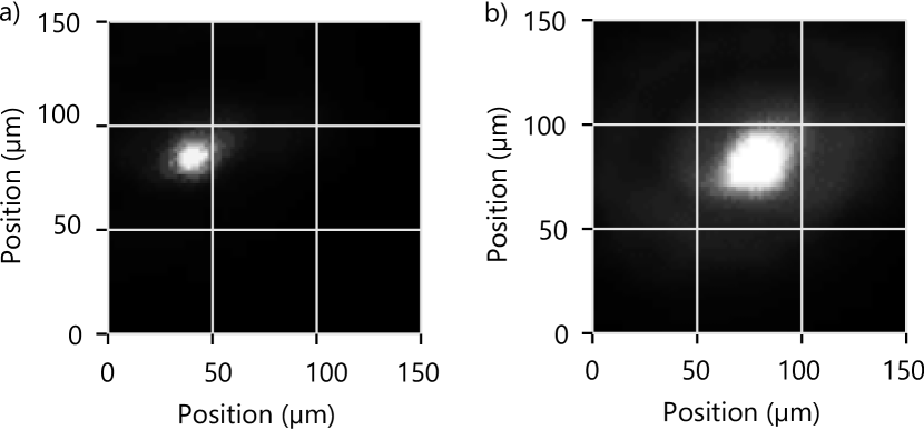
After loading, we leak air into the vacuum chamber until a pressure of is reached, thus entering the high-pressure regime. We align the vertically polarized beam to the particle by adjusting the 3D translational stage on which the focusing lens is mounted while maximizing the light scattered by the particle and imaged on the camera. An image of the particle trapped in the Paul-trap potential is shown in Fig. 2a. At this point, we use low optical power, on the order of a few milliwatts in each arm. Thus, the laser beams produce negligible optical forces, and the light is solely for particle detection. To align the second beam’s path to that of the first, we maximize the coupling of light from the second beam into the output collimator of the first, adjusting only components that do not affect the alignment of the first beam. At this point, the two beam paths overlap and the beam waists are aligned to the particle at the center of the Paul trap.
To form a stable optical trap, we increase the power of the laser to between and in each beam. An image of an optically trapped particle is shown in Fig. 2b. As illustrated in the right inset of Fig. 1, the potential minima of the Paul trap and the optical trap do not coincide. As a result, optical trapping displaces the particle from the Paul trap center. The difference of the particle positions in Fig. 2a and Fig. 2b is , in good agreement with the expected displacement of calculated from the NA values.
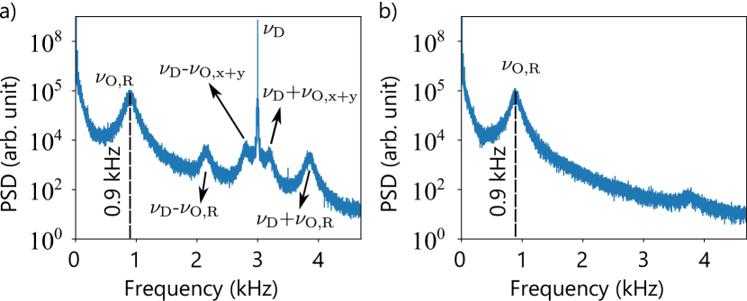
Next, we analyze the motion of the particle in the optical trap. Fig. 3a shows the power spectral density (PSD) of the particle’s center-of-mass (CoM) motion in the optical trap while the Paul trap is active. The sharp peak at frequency corresponds to the Paul-trap drive frequency. The resonance of the particle’s motion in the radial plane of the optical trap, i.e., in the plane defined by the vectors and , is at frequency . The and trap frequencies are degenerate due to the symmetry of the dual-beam trap along the beam propagation axis. The radial motion produces sidebands around at frequencies and . From the radial frequencies and the beam diameter of at the particle’s equilibrium position, we estimate the potential depth to be . Particle oscillations in the beam propagation direction are at frequency . The peak of the motion along this direction is beneath the low-frequency noise of the detection system. However, sidebands produced by this motion are visible at frequencies and . We cannot assign a potential to the forces acting along the beam propagation direction because they are non-conservative scattering forces [17], but we can estimate the work needed to remove the particle from the trap: .
As the last step of the particle transfer at high pressure, we switch off the Paul trap drive by ramping down the voltage linearly over . We keep the endcap voltage on since the field of the endcap electrodes has a negligible influence on the particle in the optical trap. Figure 3b shows the PSD of the particle motion while the Paul trap is inactive. Only a peak corresponding to radial motion in the optical trap is present. The peak coincides with the peak in Fig. 3a, which suggests that the influence of the Paul trap on the optically trapped particles is negligible. The small bump around is produced by the noise of the detection system. We can also transfer the particle back from the optical trap to the Paul trap by switching on the Paul-trap potential and decreasing the optical power in the dual-beam trap.
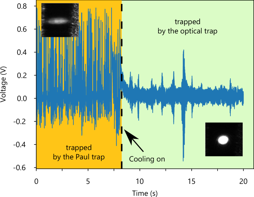
Finally, we study the transfer process at low pressure. Below , the motion of the particle in the optical trap becomes unstable, as also observed in other experiments [18, 19, 20]. Feedback cooling allows the particle to be stabilized at these pressures [21, 22]. Here, we apply electrical feedback cooling along the direction [13], which allows us to transfer the particle from the Paul trap to the optical trap at . Transfer at lower pressures might be possible if we were to apply feedback cooling along all three spatial directions. However, the current experimental setup does not allow it: electronics to extract the motion along the beam propagation direction are not installed, and the feedback force lies in the plane defined by the vectors and . Figure 4 shows a time trace measured with the QPD during the transfer process. The region on the left side of the dashed line corresponds to the motion of the particle in the Paul trap. The motion is driven by the scattering force produced by the laser beams. The upper-left inset shows a snapshot of this motion captured with the camera. When feedback cooling is activated, the particle is captured by the optical trap. It is then confined to a smaller spatial region, as can be seen from the time trace to the right of the dashed line and from the snapshot in the lower-right inset. In order to provide a safety net in case the particle escapes the optical trap, we keep the Paul trap active during this measurement.
IV Conclusion
In conclusion, we have built a hybrid trap for microparticles, combining a linear Paul trap and a dual-beam optical trap. If higher optical powers are used, the method can be extended to particles of smaller size. A particle was transferred from the Paul trap to the optical trap at pressures above , where optical trapping is stable. With the help of feedback cooling along one axis, we also transferred the particle from the Paul trap to the optical trap at . We have thus demonstrated a method of loading particles into optical traps that — when combined with feedback cooling along three axes — is expected to be compatible with UHV pressures, at which isolation from the environment is sufficient for future experiments in the quantum regime[1, 2].
Acknowledgements.
We thank Alexander Eberhardter and Marius Trojer for helpful discussions. This work was supported by Austrian Science Fund (FWF) Project No. Y951 and by the ESQ Discovery grant “Sympathetic detection and cooling of nanoparticles levitated in a Paul trap” of the Austrian Academy of Sciences.Author declarations
Conflict of Interest
The authors have no conflicts to disclose.
Data availability
The data that support the findings of this study are available from the corresponding author upon reasonable request.
References
- Gonzalez-Ballestero et al. [2021] C. Gonzalez-Ballestero, M. Aspelmeyer, L. Novotny, R. Quidant, and O. Romero-Isart, “Levitodynamics: Levitation and control of microscopic objects in vacuum,” Science 374, eabg3027 (2021).
- Millen et al. [2020] J. Millen, T. S. Monteiro, R. Pettit, and A. N. Vamivakas, “Optomechanics with levitated particles,” Rep. Prog. Phys. 83, 026401 (2020).
- Ashkin [1970] A. Ashkin, “Acceleration and trapping of particles by radiation pressure,” Phys. Rev. Lett. 24, 156–159 (1970).
- Paul [1990] W. Paul, “Electromagnetic traps for charged and neutral particles,” Rev. Mod. Phys. 62, 531–540 (1990).
- Hsu et al. [2016] J.-F. Hsu, P. Ji, C. W. Lewandowski, and B. D’Urso, “Cooling the motion of diamond nanocrystals in a magneto-gravitational trap in high vacuum,” Scientific Reports 6, 30125 (2016).
- Millen et al. [2015] J. Millen, P. Z. G. Fonseca, T. Mavrogordatos, T. S. Monteiro, and P. F. Barker, “Cavity cooling a single charged levitated nanosphere,” Phys. Rev. Lett. 114, 123602 (2015).
- Conangla, Rica, and Quidant [2020] G. P. Conangla, R. A. Rica, and R. Quidant, “Extending vacuum trapping to absorbing objects with hybrid Paul-optical traps,” Nano Lett. 20, 6018–6023 (2020).
- Schaetz [2017] T. Schaetz, “Trapping ions and atoms optically,” J. Phys. B 50, 102001 (2017).
- Bykov et al. [2019] D. S. Bykov, P. Mestres, L. Dania, L. Schmöger, and T. E. Northup, “Direct loading of nanoparticles under high vacuum into a Paul trap for levitodynamical experiments,” Appl. Phys. Lett. 115, 034101 (2019).
- Weiss et al. [2021] T. Weiss, M. Roda-Llordes, E. Torrontegui, M. Aspelmeyer, and O. Romero-Isart, “Large quantum delocalization of a levitated nanoparticle using optimal control: Applications for force sensing and entangling via weak forces,” Phys. Rev. Lett. 127, 023601 (2021).
- Schmidt et al. [2012] O. A. Schmidt, M. K. Garbos, T. G. Euser, and P. S. J. Russell, “Metrology of laser-guided particles in air-filled hollow-core photonic crystal fiber,” Opt. Lett. 37, 91 (2012).
- Gittes and Schmidt [1998] F. Gittes and C. F. Schmidt, “Interference model for back-focal-plane displacement detection in optical tweezers,” Opt. Lett. 23, 7 (1998).
- Dania et al. [2021] L. Dania, D. S. Bykov, M. Knoll, P. Mestres, and T. E. Northup, “Optical and electrical feedback cooling of a silica nanoparticle levitated in a Paul trap,” Phys. Rev. Research 3, 013018 (2021).
- Note [1] Bangs Laboratories Inc.
- Asenbaum et al. [2013] P. Asenbaum, S. Kuhn, S. Nimmrichter, U. Sezer, and M. Arndt, “Cavity cooling of free silicon nanoparticles in high vacuum,” Nat. Commun. 4, 2743 (2013).
- Millen et al. [2016] J. Millen, S. Kuhn, F. Patolsky, A. Kosloff, and M. Arndt, “Cooling and manipulation of nanoparticles in high vacuum,” in Proc. SPIE, Vol. 9922 (2016) p. 99220C.
- Novotny and Hecht [2012] L. Novotny and B. Hecht, Principles of Nano-Optics, 2nd ed. (Cambridge University Press, New York, 2012).
- Kiesel et al. [2013] N. Kiesel, F. Blaser, U. Delić, D. Grass, R. Kaltenbaek, and M. Aspelmeyer, “Cavity cooling of an optically levitated submicron particle,” Proc. Natl. Acad. Sci. USA 110, 14180–14185 (2013).
- Millen et al. [2014] J. Millen, T. Deesuwan, P. Barker, and J. Anders, “Nanoscale temperature measurements using non-equilibrium Brownian dynamics of a levitated nanosphere,” Nat. Nanotechnol. 9, 425–429 (2014).
- Price et al. [2015] C. J. Price, T. D. Donnelly, S. Giltrap, N. H. Stuart, S. Parker, S. Patankar, H. F. Lowe, D. Drew, E. T. Gumbrell, and R. A. Smith, “An in-vacuo optical levitation trap for high-intensity laser interaction experiments with isolated microtargets,” Rev. Sci. Instrum. 86, 033502 (2015).
- Li, Kheifets, and Raizen [2011] T. Li, S. Kheifets, and M. G. Raizen, “Millikelvin cooling of an optically trapped microsphere in vacuum,” Nat. Phys. 7, 527–530 (2011).
- Gieseler et al. [2012] J. Gieseler, B. Deutsch, R. Quidant, and L. Novotny, “Subkelvin parametric feedback cooling of a laser-trapped nanoparticle,” Phys. Rev. Lett. 109, 103603 (2012).