Capacitively coupled distinct mechanical resonators for room temperature phonon-cavity electromechanics
Abstract
Coupled electromechanical resonators that can be independently driven/detected and easily integrated with external circuits are essential for exploring mechanical modes based signal processing. Here, we present a room temperature phonon-cavity electromechanical system, consisting of two distinct resonators: a silicon nitride electromechanical drum capacitively coupled to an aluminum one. We demonstrate electromechanically induced transparency and amplification in a two-tone driving scheme and observe the phonon-cavity force affecting the mechanical damping rates of both movable objects. We also develop an analytical model based on linearly coupled motion equations, which captures the optomechanical features in the classical limit and enables to fit quantitatively our measurements. Our results open up new possibilities in the study of phonon-cavity based signal processing in the classical and potentially in the future in the quantum regimes.
keywords:
phonon-cavity, coupled mechanical resonators, membrane, two-tone, interference1 Introduction
Micro- and nano-electromechanical systems (MEMS and NEMS), allowing mechanical displacements to couple with electrical and optical signals, have been studied for various applications and fundamental research 1. The specific features of tiny scale and high quality factor are attractive for sensing applications 2, 3. Their intrinsic nonlinearity and mechanical transduction design are explored for developing logic gates 4, 5, radio frequency (RF) amplifiers 6 and memory nodes 7. In recent years, great efforts have been made for investigating mode coupling, which exists between different mechanical modes in a single system and between different resonators. Not only because the coupled mechanical modes enhance the sensitivity in detection 3, but because they also give access to energy exchange between two different mechanical modes 8, 9, which enables e.g. to transmit/filter information in different frequency bands10. Besides, mode coupling offers an opportunity to simulate quantum systems by emulating a classical two-level system, and opens up new applications in quantum information processing by using NEMS/MEMS integrated optomechanical systems 11, 12, 13.
Inspired by recent achievements in optomechanics, the concept of phonon-cavity has been widely exploited in studies of mechanical mode coupling 14, 15. In order to generate phonon-phonon interactions, the typical method is to implement the mechanical mode having the higher resonance frequency in the coupled system as a “phonon cavity” (in analogy with an optical cavity), and to sideband pump it at the frequency , where is the resonance frequency of the other mode. Rich physics from optomechanics has been inherited in phonon-cavity electromechancial systems, such as the optical spring effect or the amplification/de-amplification of the mechanical damping rate, which can lead to self-sustained oscillation states generated by the cavity force 15, 16, 17. These coupled mechanical modes also enrich existing optomechanical functions. It has been proved that an optomechanical system, consisting of coupled mechanical modes, exhibits additional flexibility in adjusting the optomechanical transparency window for signal processing and increasing information storage time 12, 13. In most phonon-cavity schemes, the mechanical mode coupling is created between different mechanical modes with a single resonator by means of an intrinsic nonlinearity, or between different resonators by using physical connections transmitting a displacement-induced tension 15, 8, 2, 18, 19, 20. However, mechanical coupling design yields implementation complexities in optimization of the coupling between distinct resonators, and poses a challenge when electromechanical devices with higher resonance frequencies and flexible frequency tunability are required. Compared to these more common mechanical coupling designs, capacitive coupling schemes bring a convenient capability to couple distributed electromechanical resonators by giving them the capability to directly exchange information with each other via cavity phonons 12, 13. However, it is still challenging to realize directly coupled mechanical resonators via a capacitive coupling scheme 21, 22.
In this work, we present mechanical motion transduction between two capacitively coupled, and distinct electromechanical resonators, consisting of an Al drum and a SiN drum. Both resonators can be driven and detected independently. In a two-tone driving scheme, we explore phonon-cavity electromechanics based on a simple theoretical model which is analogue to microwave optomechanics, and experimentally demonstrate electromechanically induced transparency and amplification at room temperature, by pumping the phonon-cavity at its sideband to generate phonon-phonon interactions. Modulations of the mechanical damping rate (with respect to the applied driving tone) have been observed in both coupled drum resonators, and exhibit the trend expected by the theoretical model. These results indicate that this new type of device design could serve for phonon-based information processing in both classical and quantum regimes, such as information storage and tunable filter 12, 13.
The device structure investigated in this work consists of two distinct electromechanical resonators. One of them is a silicon nitride (SiN) drum, 80 nm in thickness, covered with an aluminum (Al) thin film 25 nm in thickness, which has been fabricated from a silicon substrate covered with a stoichiometric silicon nitride thin film, 1 GPa tensile stress. The SiN drum measured in this work is 36 m in diameter. The other coupled resonator is an Al drum having a diameter of 40 m, suspended on top of the SiN drum. Details of device fabrication have been reported in our previous work 23.
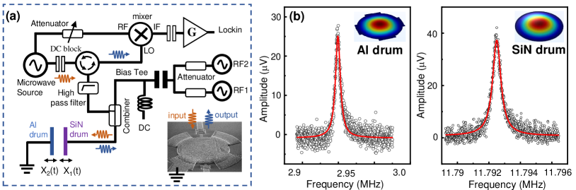
The measurement setup is schematically depicted in Figure 1 (a). Mechanical motions of both electromechanical resonators can be independently excited by passing RF signals combined with dc voltages to generate an electrostatic driving force. All the measurements are performed at room temperature, under vacuum ( mbar) to minimize air damping. Figure 1 (b) shows linear responses of both Al drum and SiN drum resonators, for their fundamental modes. For the Al drum resonator, the resonance frequency is /(2) 2.95 MHz with a quality factor 358. A finite element simulation is consistent with a low tensile stress in the Al film 40 MPa, which could be induced during the electron beam evaporation process. The SiN drum vibrates at frequency /(2) 11.792 MHz with a quality factor 1.8, far from the resonance range of the Al drum resonator. In the experiment, we take the SiN resonator as the phonon-cavity. It actually presents an energy leaking rate which is much smaller than that of the coupled Al drum, contrary to standard optomechanical systems.
1.1 RESULTS AND DISCUSSIONS
Electromechanical capacitive coupling model. The whole device structure can be viewed as a parallel plate capacitor , where each plate is a membrane drum resonator, as shown in Figure 1 (a). The mechanical displacement of each membrane is described by and resonating at the frequency and respectively far from each other, with . Driven by the electrostatic force = , we therefore model these two capacitively coupled drums in the linear response regime via the following coupled equations of motion for the displacements and ,
| (1) | ||||
Here, are the mechanical damping rates and are the effective masses of each drum. The driving force, acting on a simple parallel plate capacitor, is truncated at the second order in a Taylor expansion, and is the initial capacitance between the two membranes separated by a distance . In Eq.1, the approximation has been made by considering the typical situation encountered in measurements: . The static contribution has been dropped of the equation since it cannot drive resonantly the modes. Following the concept of cavity optomechanics, the mechanical resonator having the higher resonance frequency in the coupled system is chosen as the phonon-cavity. In a two-tone driving scheme, we exploit one driving tone with frequency to weakly probe one of the coupled membranes around its resonance frequency ( or ), and the other tone with frequency to pump the phonon-cavity at its sideband . The carrying the two tones therefore can be written in the form = . The and are complex amplitudes corresponding to the and the components, respectively. Eq.1 is solved in the rotating frame through looking for the mechanical displacement = mainly driven by the probe signal, and the displacement also depends on the interaction between the probe tone and the pump tone. The are the slowly varying complex amplitudes of the mechanical displacement, corresponding to each membrane’s motion. In analogy with microwave optomechanics, we define the coupling strength between the phonon-cavity (SiN membrane, with index 1) and its coupled Al drum (with index 2) as and the single phonon coupling strength =, where is the zero-point fluctuations of the mechanical mode indexed 2 with resonance frequency . While the experiment is by no means anywhere close to the quantum regime, we introduce this language as a commodity for a direct comparison with the usual formalism of optomechanics. We first consider a two-tone driving scheme, which has been generally investigated in optomechanics. The phonon-cavity is probed with a frequency = and is pumped at the frequency =. The parameter is therefore a frequency detuning from frequency for the probe tone. The parameter is a frequency detuning for the pump, from the frequency . Solving Eq.1, the probed mechanical displacement is given by
| (2) |
where = is the phonon number generated by the pumping force = and = is the driving force generated by the probe signal. Both and are complex amplitudes. The and are susceptibilities of the phonon-cavity and the coupled electromechanical resonator. The “-” and “+” symbols in Eq.2 correspond to a “red” or “blue” sideband pumping scheme, respectively. Similarly, the probe tone can be applied at = in order to measure the Al drum response, whose theoretical analyses are shown in the SI.
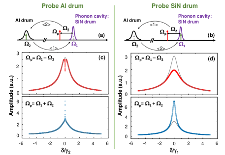
The probed mechanical displacement exhibits a behavior similar to optomechanically induced transparency and amplification 24, 25. In this two-tone scheme, the mechanical interaction can be decomposed into two coherent steps for phonon exchange, as indicated in the Figure 2(a) and 2(b), where each graph corresponds to one of our two different probing cases. In a first step, the probe and pump tone create a “radiation pressure” force acting on the unprobed membrane that excites its mechanical vibrations, corresponding to the process in the Figure 2(a) and 2(b). Then, these generated mechanical phonons are fed back to the probed resonator, corresponding to the process . An interference therefore is built between these phonons described by the term acting on the unprobed membrane in Eq. 2 and the initial probe signal corresponding the term . This interference can be destructive or constructive, which depends on pumping the cavity at its red or blue sideband. Impacts of this interference on the resonance peaks measured with the two probe configurations are illustrated in Figure 2(c) and 2(d), taking taking into account the fact that the phonon cavity linewidth is about two orders smaller than that of the coupled Al drum (our experimental conditions). As indicated in Eq.2, the linewidth of the unprobed mechanical resonator determines the frequency bandwidth of the transparency and amplification effects. For instance, when the phonon-cavity is red sideband pumped, the Lorentzian curve of the Al drum mechanical response exhibits a narrow dip inside its lineshape due to the fact , as shown in Figure 2(c). On the contrary, the probed signal passing through the SiN drum is fully suppressed, as the determines the linewidth of the transparency window. This phenomenon is quite different from conventional optomechanical systems in which the mechanical damping rate is usually much smaller than that of the coupled cavity. These results demonstrate that both transparency and amplification windows can be controlled through engineering the mechanical damping rate in the phonon-cavity system.
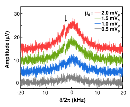
Electromechanically induced transparency and amplification. In order to build the interference process, one of the key points is that the unprobed mechanical resonator should provide enough phonons to be fed back by the pump tone, generating the interference with the initial probe tone. The motion equation Eq.1 indicates that the energy transferred between the two movable membranes is determined by the effective pumping force , when the probe tone is driving the mechanical displacement around its resonance frequency . Therefore, the probe tone should have a large amplitude in order to increase the pump efficiency and provide a large number of phonons for the interference process. To demonstrate it, the phonon-cavity is red sideband pumped at a frequency = using =-2.5 kHz with a fixed pump amplitude = 100 mVp and = 2 V. Figure 3 shows the linear response of the Al drum probed by different , as a function of the frequency detuning . At the largest drive amplitudes, a clear dip is visible when the two detunings are matched, = .
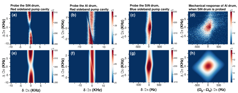
Electromechanical responses of these coupled resonators have been measured as a function of the pump tone detuning and the probe frequency detuning , for both red and blue sideband pumping schemes, as shown in Figure 4(a)-4(d). These measurement results clearly indicate that the linewidth of the interference window corresponding to the pump tone tuning is related to the unprobed membrane. This is because the unprobed membrane in the coupled system acts as a phonon transfer station. Within the bandwidth of the unprobed resonator, phonons can be generated from the interaction between the pump and the probe tone and can coherently create constructive or destructive interferences with the probe tone. Figure 4(c) and 4(d) show the simultaneous measurement results of the electromechanical responses of the probed and the unprobed membranes, in which the phonon-cavity is driven at a frequency = and is pumped at its blue sideband =. Figure 4(c) clearly shows a constructive interference result as the probed signals have been amplified within the interference window and the Figure 4(d) indicates phonon generation in the mechanical mode of the Al drum. The mechanical displacements of both membranes , corresponding to different driving and pumping schemes, have been calculated based on the capacitive coupling model described by Eq. 1. The calculated mechanical displacements are converted into electrical signal amplitude in a microwave measurement scheme and are shown in Figure 4(e)-(h), by using the relation = 23. Here, and are the frequency and the amplitude of the microwave signal for detection, respectively. The parameter is the impedance of the measurement chain (here, 50 Ohm). The measurement results have been quantitatively fitted within 10 error bar by taking effective masses for the SiN membrane of 4.4 kg and for the Al drum of 4.41 kg, and by using the experimental parameters mentioned above.
Besides, we also evaluate the maximum coupling rate = by taking the largest pump force performed in this measurement, which has been generated by applying = 4 V and = 70 mVp. It gives 1024 rad/s , which remains smaller than and . It means that the pumping force does not provide enough phonons to drive the coupled mechanical system into the so-called strong coupling regime. In the present room temperature measurement, the pumping force is mainly limited by the large thermal background noise due to the heating effects brought in by the high pumping power. On the contrary, in the low temperature range (e.g. mK range), this limitation will be greatly suppressed. In addition, the typical damping rates of both SiN and Al mechanical resonators are 102 Hz in mK range 26, 27 with resonance frequencies in the MHz range, which could give this kind of device an access to the strong coupling regime.
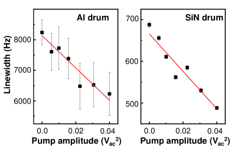
Backaction effects on mechanical damping rate. In optomechanical systems, the mechanical damping rate can be modulated by the cavity backaction force, which comes from the confined electromagnetic energy generated by pumping the coupled optical or microwave cavity at its sideband. Two capacitively coupled mechanical resonators give more degrees of freedom and provide an opportunity to observe the cavity force acting on both resonators, including the one acting as a phonon-cavity. In order to observe this effect, we exploit a large ac signal to pump the blue sideband of the phonon-cavity, and apply a small ac one to respectively excite mechanical displacements of the SiN or Al drum to be just above the noise floor of the measurement chain. As shown in Figure 5, the linewidth of both coupled membranes decreases with increasing the pump power (), exhibiting the typical “optical (anti-)damping effect” 28. We can use a single-tone driving scheme to model this effect in two capacitively coupled membranes based on Eq. 1, in which the phonon cavity is pumped at the frequency . Here, the is a global frequency detuning, with for the blue sideband and for the red sideband. The sideband scheme pumping the cavity gives rise to two satellite signals, corresponding to Stokes- and anti-Stokes scattering 29. The mechanical susceptibility is altered due to interactions between the pump tone and these generated Stokes and anti-Stokes processes, yielding modulations of the mechanical damping rates 28. By employing a similar approach as the one applied to the electric circuit modeling of microwave optomechanics 29, we therefore deduce the additional damping term of the Al drum (with index 2) due to the back-action force of the phonon-cavity, but also the additional damping term for the phonon-cavity (see details in SI), as shown in Eq.3. The additional damping terms make the initial mechanical damping rate become =+,
| (3) | ||||
In our measurement of a blue sideband pumping scheme with =, Eq.3 demonstrates the fact that the effective damping rate of the Al drum is inversely proportional to the initial damping rate of the coupled phonon-cavity, , in accordance with the “optical damping effect” in an optomechanical system. While conversely, for the damping rate of the phonon-cavity, is . If we consider the experimental condition , , Eq. 3 leads to /. In our measurement, slopes of the linewidth versus can be obtained from the linear fit of the measurement results shown in Figure 5, for both membranes. The ratio between these slopes gives 11.8, which is in extremely good agreement with the value of /12.0 expected from our analytic model.
2 SUMMARY
In conclusion, we have built a phonon-cavity optomechanical analogue, made of two distinct electromechanical resonators, consisting of a SiN drum and an Al drum. A simple coupling model is built to describe the mechanical motion transduction within the two capacitively coupled electromechanical resonators. In a two-tone driving scheme, electromechanically induced transparency and amplification of the injected signals have been created and manipulated at room temperature. The unique device structure allows to observe the phonon-cavity force affecting the mechanical damping rates of both coupled mechanical resonators. These optomechanical features are captured by the linear mechanical motion equations, providing theoretical analyses that quantitatively fit our measurement results. These investigations establish connections between a setup with two directly coupled movable objects and a standard optomechanical system in the classical regime. This type of capacitively coupled distinct electromechanical systems can be useful to build multimode optomechanical systems for both the classical and quantum regimes, providing a new degree of freedom in engineering photon/phonon processing, such as signal delay, storage and amplification.
X.Z. conceived the design of the experiment. A.P. collected data, H.X. participated theoretical modeling, S.V. fabricated the device. X.Z built the setup, performed the measurements, and developed the analytic model. X.Z. wrote the manuscript. All authors contributed to scientific discussions and corrections of the manuscript. Both E.C. and X.Z. supervised the project.
We would like to acknowledge support from the STaRS-MOC project No. 181386 from Region Hauts-de-France (X.Z.), the project No. 201050 from ISITE-MOST (X.Z.), the ERC CoG grant ULT-NEMS No. 647917 (E.C.). The research leading to these results has received funding from the European Union’s Horizon 2020 Research and Innovation Programme, under grant agreement No. 824109, the European Microkelvin Platform (EMP). This work was partly supported by the French Renatech network and RF-MEMS platform in IEMN. The authors acknowledge SMMiL-E, IRCL, and Contrat de Plan Etat-Région CPER Cancer 2015-2020 for technical support on wire bonding.
-
•
Filename: Analytical calculation for two-tone driving scheme
-
•
Filename: Analytical calculation for single-tone sideband pumping scheme: analogy to optomechanical damping effect
References
- Bachtold et al. 2022 Bachtold, A.; Moser, J.; Dykman, M. Mesoscopic physics of nanomechanical systems. arXiv preprint arXiv:2202.01819 2022,
- Spletzer et al. 2006 Spletzer, M.; Raman, A.; Wu, A. Q.; Xu, X.; Reifenberger, R. Ultrasensitive mass sensing using mode localization in coupled microcantilevers. Applied Physics Letters 2006, 88, 254102
- Spletzer et al. 2008 Spletzer, M.; Raman, A.; Sumali, H.; Sullivan, J. P. Highly sensitive mass detection and identification using vibration localization in coupled microcantilever arrays. Applied Physics Letters 2008, 92, 114102
- Guerra et al. 2010 Guerra, D. N.; Bulsara, A. R.; Ditto, W. L.; Sinha, S.; Murali, K.; Mohanty, P. A noise-assisted reprogrammable nanomechanical logic gate. Nano letters 2010, 10, 1168–1171
- Mahboob et al. 2011 Mahboob, I.; Flurin, E.; Nishiguchi, K.; Fujiwara, A.; Yamaguchi, H. Interconnect-free parallel logic circuits in a single mechanical resonator. Nature communications 2011, 2, 1–7
- Karabalin et al. 2011 Karabalin, R.; Lifshitz, R.; Cross, M.; Matheny, M.; Masmanidis, S.; Roukes, M. Signal amplification by sensitive control of bifurcation topology. Physical review letters 2011, 106, 094102
- Mahboob and Yamaguchi 2008 Mahboob, I.; Yamaguchi, H. Bit storage and bit flip operations in an electromechanical oscillator. Nature nanotechnology 2008, 3, 275–279
- Okamoto et al. 2013 Okamoto, H.; Gourgout, A.; Chang, C.-Y.; Onomitsu, K.; Mahboob, I.; Chang, E. Y.; Yamaguchi, H. Coherent phonon manipulation in coupled mechanical resonators. Nature Physics 2013, 9, 480–484
- Faust et al. 2012 Faust, T.; Rieger, J.; Seitner, M. J.; Krenn, P.; Kotthaus, J. P.; Weig, E. M. Nonadiabatic dynamics of two strongly coupled nanomechanical resonator modes. Physical review letters 2012, 109, 037205
- Bannon et al. 2000 Bannon, F. D.; Clark, J. R.; Nguyen, C.-C. High-Q HF microelectromechanical filters. IEEE Journal of solid-state circuits 2000, 35, 512–526
- Faust et al. 2013 Faust, T.; Rieger, J.; Seitner, M. J.; Kotthaus, J. P.; Weig, E. M. Coherent control of a classical nanomechanical two-level system. Nature Physics 2013, 9, 485–488
- Fan et al. 2015 Fan, L.; Fong, K. Y.; Poot, M.; Tang, H. X. Cascaded optical transparency in multimode-cavity optomechanical systems. Nature communications 2015, 6, 1–6
- Shahidani et al. 2013 Shahidani, S.; Naderi, M.; Soltanolkotabi, M. Control and manipulation of electromagnetically induced transparency in a nonlinear optomechanical system with two movable mirrors. Physical Review A 2013, 88, 053813
- Mahboob et al. 2012 Mahboob, I.; Nishiguchi, K.; Okamoto, H.; Yamaguchi, H. Phonon-cavity electromechanics. Nature Physics 2012, 8, 387–392
- Sun et al. 2016 Sun, F.; Dong, X.; Zou, J.; Dykman, M. I.; Chan, H. B. Correlated anomalous phase diffusion of coupled phononic modes in a sideband-driven resonator. Nature communications 2016, 7, 1–8
- Zeng and Zeng 2021 Zeng, Q.; Zeng, K. Strong phonon-cavity coupling and parametric interaction in a single microcantilever under ambient conditions. Journal of Physics D: Applied Physics 2021, 54, 475307
- Cattiaux et al. 2020 Cattiaux, D.; Zhou, X.; Kumar, S.; Golokolenov, I.; Gazizulin, R.; Luck, A.; de Lépinay, L. M.; Sillanpää, M.; Armour, A.; Fefferman, A., et al. Beyond linear coupling in microwave optomechanics. Physical Review Research 2020, 2, 033480
- Mahboob et al. 2015 Mahboob, I.; Perrissin, N.; Nishiguchi, K.; Hatanaka, D.; Okazaki, Y.; Fujiwara, A.; Yamaguchi, H. Dispersive and dissipative coupling in a micromechanical resonator embedded with a nanomechanical resonator. Nano letters 2015, 15, 2312–2317
- Karabalin et al. 2009 Karabalin, R.; Cross, M.; Roukes, M. Nonlinear dynamics and chaos in two coupled nanomechanical resonators. Physical Review B 2009, 79, 165309
- De Alba et al. 2016 De Alba, R.; Massel, F.; Storch, I. R.; Abhilash, T.; Hui, A.; McEuen, P. L.; Craighead, H. G.; Parpia, J. M. Tunable phonon-cavity coupling in graphene membranes. Nature nanotechnology 2016, 11, 741–746
- Siskins et al. 2021 Siskins, M.; Sokolovskaya, E.; Lee, M.; Mañas-Valero, S.; Davidovikj, D.; Van Der Zant, H. S.; Steeneken, P. G. Tunable strong coupling of mechanical resonance between spatially separated FePS3 nanodrums. Nano letters 2021,
- Huang et al. 2013 Huang, P.; Wang, P.; Zhou, J.; Wang, Z.; Ju, C.; Wang, Z.; Shen, Y.; Duan, C.; Du, J. Demonstration of motion transduction based on parametrically coupled mechanical resonators. Physical Review Letters 2013, 110, 227202
- Zhou et al. 2021 Zhou, X.; Venkatachalam, S.; Zhou, R.; Xu, H.; Pokharel, A.; Fefferman, A.; Zaknoune, M.; Collin, E. High-Q silicon nitride drum resonators strongly coupled to gates. Nano Letters 2021,
- Weis et al. 2010 Weis, S.; Rivière, R.; Deléglise, S.; Gavartin, E.; Arcizet, O.; Schliesser, A.; Kippenberg, T. J. Optomechanically induced transparency. Science 2010, 330, 1520–1523
- Hocke et al. 2012 Hocke, F.; Zhou, X.; Schliesser, A.; Kippenberg, T. J.; Huebl, H.; Gross, R. Electromechanically induced absorption in a circuit nano-electromechanical system. New Journal of Physics 2012, 14, 123037
- Zhou et al. 2019 Zhou, X.; Cattiaux, D.; Gazizulin, R.; Luck, A.; Maillet, O.; Crozes, T.; Motte, J.-F.; Bourgeois, O.; Fefferman, A.; Collin, E. On-chip Thermometry for Microwave Optomechanics Implemented in a Nuclear Demagnetization Cryostat. Physical Review Applied 2019, 12, 044066
- Teufel et al. 2011 Teufel, J. D.; Donner, T.; Li, D.; Harlow, J. W.; Allman, M.; Cicak, K.; Sirois, A. J.; Whittaker, J. D.; Lehnert, K. W.; Simmonds, R. W. Sideband cooling of micromechanical motion to the quantum ground state. Nature 2011, 475, 359–363
- Aspelmeyer et al. 2014 Aspelmeyer, M.; Kippenberg, T. J.; Marquardt, F. Cavity optomechanics. Reviews of Modern Physics 2014, 86, 1391
- Zhou et al. 2021 Zhou, X.; Cattiaux, D.; Theron, D.; Collin, E. Electric circuit model of microwave optomechanics. Journal of Applied Physics 2021, 129, 114502