2021
[2]\fnmMichael \surDe Volder
[4]\fnmJames \surElliott
[1]\fnmSishen \surXie
[2]\fnmAdam \surBoies
1]\orgdivBeijing National Laboratory for Condensed Matter Physics, \orgnameInstitute of Physics, Chinese Academy of Sciences, \cityBeijing, \postcode100190, \countryChina
2]\orgdivDepartment of Engineering, \orgnameUniversity of Cambridge, \cityCambridge, \postcodeCB2 1PZ, \countryUK
3]\orgdivMOE Key Laboratory of Enhanced Heat Transfer and Energy Conservation, Beijing Key Laboratory of Heat Transfer and Energy Conversion, \orgnameBeijing University of Technology, \cityBeijing, \postcode100124, \countryChina
4]\orgdivDepartment of Materials Science and Metallurgy, \orgnameUniversity of Cambridge, \cityCambridge, \postcodeCB3 0FS, \countryUK
Simultaneously Enhanced Tenacity, Rupture Work, and Thermal Conductivity of Carbon Nanotubes Fibers by Increasing the Effective Tube Contribution
Abstract
Although individual carbon nanotubes (CNTs) are superior as constituents to polymer chains, the mechanical and thermal properties of CNT fibers (CNTFs) remain inferior to commercial synthetic fibers due to the lack of synthesis methods to embed CNTs effectively in superstructures. The application of conventional techniques for mechanical enhancement resulted in a mild improvement of target properties while achieving parity at best on others. In this work, a Double-Drawing technique is developed to deform continuously grown CNTFs and rearrange the constituent CNTs in both mesoscale and nanoscale morphology. Consequently, the mechanical and thermal properties of the resulting CNTFs can be jointly improved, and simultaneously reach their highest performances with specific strength (tenacity) , work of rupture , and thermal conductivity , despite starting from commercial low-crystallinity materials (). The processed CNTFs are more versatile than comparable carbon fiber, Zylon, Dyneema, and Kevlar. Furthermore, based on evidence of load transfer efficiency on individual CNTs measured with In-Situ Stretching Raman, we find the main contributors to property enhancements are (1) the increased proportion of load-bearing CNT bundles and (2) the extension of effective length of tubes attached on these bundles.
keywords:
carbon nanotubes, fibers, strength, toughness, thermal conductivity, raman1 Introduction
Carbon nanotube (CNT) macroscopic assemblies, like CNT fibers (CNTFs) are analogous to bulk materials of highly-conjugated polymer molecules.Fakhri2009 ; Mikhalchan2019 Correspondingly, constituent CNTs are akin to polymer chains, but with outstanding mechanical,Min-Feng2000 ; Peng2008 ; Zhang2020d thermal,Kim2001 ; Pop2006 electrical properties,Bulmer2021 ; Komatsu2021 and chemical resilience.DeVolder2013 CNT bundles are reported to possess excellent tensile strength () and Young’s modulus ().Tombler2000 ; Yu2000 ; Baughman2002 ; Bai2018 Direct-spun CNTFs can be produced continuously () with low-cost, resulting in light-weight and high flexibility fibers. However, raw direct-spun CNTFs still suffer from a 1-2 orders of magnitude degradation in properties relative to CNT bundles, and are uncompetitive with commercial carbon fibers (CF), Kevlar fibers and Zylon fibers on their corresponding specialties.
Researchers attribute the property degradation primarily to the poor arrangement of the constituent CNTs within the as-synthesized CNTFs,Mikhalchan2019 and thus they utilized various post-synthesis treatments seeking to rearrange the individual CNTs (iCNTs) and CNT bundles. However, with techniques commonly used on textile fibers (e.g. direct stretching,Koziol2007 ; Fernandez-Toribio2018 compression,Wang2014a ; Tran2016 ; Xu2016 and twistingZhang2004 ; Headrick2018 ) only minor enhancements have been achieved. In 2013, with a similar method to produce Kevlar and Zylon, the solution-spinning technique was reported to produce highly aligned and compacted CNTFsBehabtu2013 from a liquid crystal solution of CNTs in chlorosulfonic acid (CSA). The reported mechanical properties increased significantly to strengths (tenacity ) and moduli . Recently researchers stretched the Direct-spun CNTFs in CSA to obtain an aligned structureLee2019 which employed screening of van der Waals (vdW) forces in CSA,Davis2009 ; Parra-Vasquez2010 ; Ramesh2004 similar to stiffening cellulose fibers within water to screen hydrogen bonds between chains.Hearle2008 Even though the reported mechanical performances surpass those of solution-spinning CNTFs, superior performance seems only achievable on very thin CNTFs (linear density ), while those of thick CNTFs are much degraded, even poorer than raw thin CNTFs.Lee2020 The achieved density is limited to less than , indicating potential for further enhancement to the theoretical density of ideally compacted CNTs bundles ().Aliev2010 ; Behabtu2013 Meanwhile, CSA appears to have competing effects, facilitating rearrangement while hindering the load transfer within CNTFs in internal regions where remnant CSA screens vdW forces.Ramesh2004 Additionally, because phonon conduction is also impeded by the disordered microstructure in CNTFs, strategies to enhance thermal conductivity also warrant investigation. Thus, improving the properties of CNTFs while avoiding the disturbance from residual CSA is the primary motivation of our work.
Additionally, while many improvements have been reported for CNT performance, a mechanistic explanation of property enhancement is still incomplete. Most conceptual models omit the distinctive structure of CNTFs as a porous hierarchical network of long rigid iCNTs, as distinct from CF, Kevlar, or cotton yarn. Furthermore, the efficiency of load transfer between iCNTs, and focus on the different behavior of iCNTs under various loads remains to be fully investigated. Thus, our work also focuses on optimizing the mechanism applicable to hierarchical CNT networks bonded by vdW forces to guide further enhancement and to assess current processing techniques.
Here, we develop a novel Double-Drawing technique to straighten and compact the iCNTs within raw Direct-spun CNTFs, seeking a simultaneous improvement in mechanical and thermal properties. The iCNT alignment and CNTF porosity were monitored by Wide and Small-Angle X-ray Scattering and FIB cross-section analysis, as well as in-situ stretching Raman to study quantitatively the iCNTs’ behavior in various CNTFs after different levels of processing and loading. Finally, based on the experimental findings, we complement the mechanism of enhancement with two critical factors: the increased proportion of load-bearing CNT bundles and the extension of effective length of tubes attached on these bundles.
2 Results
2.1 Enhancement of CNTF with the Double-Drawing Process

In our work, the raw CNTFs are fabricated by direct spinning CNT aerogels produced with a continuous floating catalyst chemical vapor deposition (FCCVD) method. The FCCVD method is considered highly suitable for the continuous mass-production of iCNTs with a very high aspect ratio.Mikhalchan2019 These grown CNTs aggregate into bundles and then entangle as an aerogel,Boies2019 ; Kateris2020 which is subsequently densified into fibers by acetone during collection from the reactor. The as-synthesized CNTFs consist of a hierarchical network of randomly connected CNTs (Fig.1a(i), b-c). Analogous to polymer molecules in a textile fiber being held together by hydrogen bonds and/or vdW forces, the iCNTs in CNTF are held together by vdW forces in an entangled network. The vdW forces “freeze” the CNTF in a non-equilibrium curved morphology, i.e. an athermal structure.Yakobson2006
Here, to enhance the CNTF after synthesis, the connections or constraint intra and inter bundles are firstly weakened or even released by immersing the CNTF in (CSA) (Fig.1a(ii)). The protonation of CNTs by CSADavis2009 screens the vdW forces, as observed by the swelling of the CNTF in CSA. The weakened tube-tube forces thus reduce the large shear strength. Thus, the mutual lateral movement of iCNTs can occur easily, which otherwise might break CNTs if done without CSA. This process is analogous to the high humidity environment softening the hydrogen bonds between cellulose molecules before enhancing cellulose fiber.
The CNTF is then firstly drawn in CSA to a specific draw-ratio (, the extension length divided by original length), during which the crumpled CNTs are freely straightened and aligned along the fiber axis (Fig.1a(iii)), with minimal breaking of CNTs. To quantitatively study the effect of drawing in CSA, the range of is controlled from to the maximum ratio , in which the less than the failure ratio in CSA (). We find a strong dependence of on linear density () of CNTF, i.e., LD (details can be found in S1). For CNTFs the respective dependencies on and draw-ratios are observed , , and .
After drawing, the remaining CSA within CNTF still hinders the load transfer between iCNTs caused by vdW forces. Chloroform serves as the best solvent to dissolve CSA, but the fine voids in the increasingly compacted outer CNT layers hinder the outward diffusion of CSA (Fig.1a(iv)). Therefore, to remove the remaining CSA and densify the fiber, we further introduce a second drawing process, referred as “Poisson Tightening” process. After the first drawing in CSA, the fiber is immediately drawn further in chloroform with another draw-ratio, (Fig.1a(v)). When immersed in chloroform, CNTs in the outer layer solidify, significantly, thus increasing the layer’s modulus. Then under subsequent axial drawing, the resulting radial tightening, caused by the Poisson effect, further expels CSA, while solidify and compressing CNTs in the inner layers (details in S1). We also find excessive drawing, , may cause plastic deformation and break iCNTs. After the above Double-Drawing processes, the CNTFs are successively rinsed with water and acetone (Fig.1a(vi)), and finally vacuum dried for further use.
2.2 The Microstructure After Drawing

For the Double-Drawn CNTF (DD-CNTF) with full drawing ( and ), referred as fully DD-CNTF, both the mesoscale and nanoscale structure are organized. The disordered network of the raw CNTF is optimized into an aligned and tightly compacted bundle structure (Fig.1b-e). The raw thin bundles (diameter of 10-50 nm, Fig.1c) converge to much thicker bundles with diameter of 80-500 nm, as observed in the fracture end of the fully DD-CNTF (Fig.2a). Within the thick bundles, all iCNTs are tightly packed.
The alignment evolution within CNTFs is observed by Wide-Angle X-ray Diffraction (WAXD).Bedewy2009 ; Fernandez-Toribio2018 ; Kaniyoor2021 The Full-Width-at-Half-Maximum (FWHM) of the preference peak in azimuthal scan is an indicator of CNTs alignment (Fig.2b). As the draw-ratio increases to 14.5%, the FWHM decreases from to (Fig.2c). At draw-ratios above 14.5%, FWHM plateaus near , which indicates the saturation of the alignment of CNTs above the threshold level of drawing. Similar results are shown for Small-Angle X-ray Scattering (SAXS, Fig.S1) where the optimization of alignment levels off above 12% of drawing.

The evolution of voids within DD-CNTF was monitored by SEM of the cross-section cut by Focused Ion Beam (FIB). As shown in Fig.3a-c, with increasing draw-ratio, the porosity decreases and reaches minimum on the fully DD-CNTF with fine voids (more details can be found in Fig.S2). Because the area surrounded by the voids is an indicator of the cross-section of a bundle, the ever-increasing solid area also illustrates the thickening of bundles. We further checked the cross-section cut parallel to the fiber axis (Fig.3d). The remaining voids are in bead-chain configuration, indicating that the remaining voids in the fully DD-CNTF originate from the gaps between thick bundles and layers of aerogel.
2.3 Enhancement of Mechanical Properties for DD-CNTFs
The strength of fibers increase with the increasing density where the cross sectional-area diminishes for a given fiber as it is densified.Stallard2018 The cross-sectional area is poorly defined for porous nanomaterials and assemblies with ambiguous cross-sections or non-uniform diameters. Thus, to best characterize DD-CNTFs “tenacity”, i.e. “specific strength” with units of (or ), is a well-defined indicator of load and does not have the ambiguity of absolute “strength” with units of GPa. Tenacity is widely used for textile fibers and can be calculated directly by dividing stretching force with linear density (, mass/length), both of which can be unambiguously measured for fibers and porous nanomaterials.
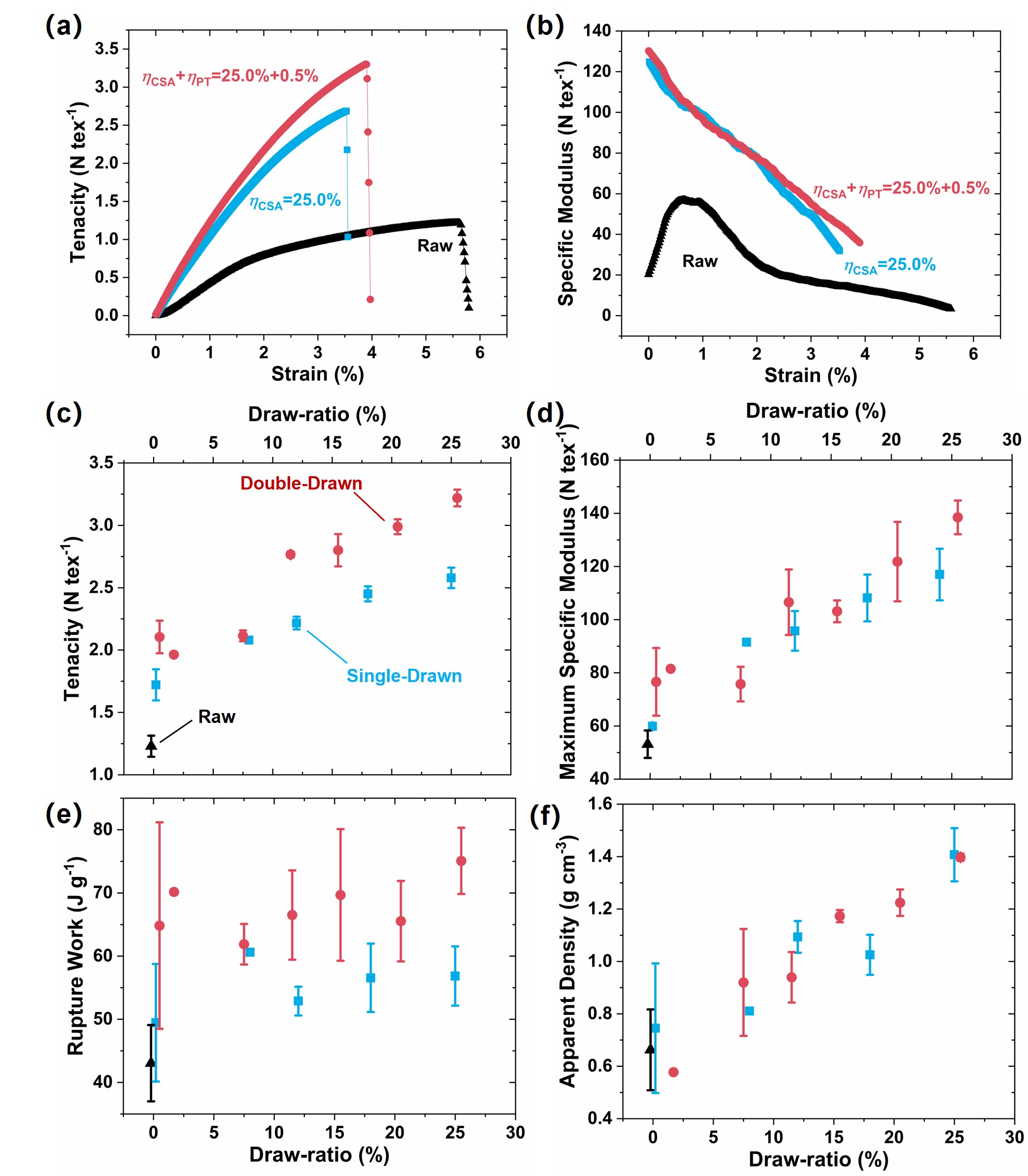
As shown in Fig.4a, compared with the raw CNTFs (black triangles), after full Double-Drawing (red dots), the fibers exhibit an increase in breaking tenacity from to . When compared with the CNTF only drawn in CSA (Single-Drawn, SD-CNTF, blue squares in Fig.4), the tenacity of the fully DD-CNTF has 23% greater tenacity without any ductility degradation, which illustrates the importance of the Poisson Tightening process. Fiber strength, when accounting for SEM-measured cross sectional areas, increases from raw fiber strength of 0.9 GPa to 4.6 GPa for fully DD-CNTFs (see Fig.S3).
With the gradual increase in the draw-ratio, both DD-CNTFs and SD-CNTFs show a monotonic increase in tenacity (Fig.4c). We find no saturation plateau on tenacity after threshold drawing as was shown with alignment (Fig.2c). The further enhancing effect from Poisson Tightening is more obvious when . Furthermore, because of the consistency of ductility before and after the Poisson Tightening (Fig.S4), the work of rupture, i.e. energy absorbed during the rupture process increased to for DD-CNTFs, from for the raw CNTF, and for SD-CNTFs.
In the corresponding tangent specific modulus-strain plots (M-S plots, Fig.4b), for both DD-CNTFs and SD-CNTFs, the modulus reduces during the tensile testing process. The rising of modulus for the raw CNTF at the beginning comes from the deformation of the iCNT network.Park2019 For CNTFs after different draw-ratios, the initial modulus (maximum modulus) monotonically increases with the rising of draw-ratio (Fig.4d) and reaches for the specific modulus of fully DD-CNTF, compared with for the raw CNTF. The close stacking and collapsed cross-section (Fig.S5) increases the CNTF apparent density from of the raw fibers to of the fully DD-CNTF (Fig.4f), which is very close to the theoretical density of ideally compacted CNTs bundle ().Aliev2010 ; Behabtu2013
It is also interesting that by only immersing in CSA, the CNTF gains increase in tenacity (Fig.4c), along with short and straight CNT bundles on the fiber surface (Fig.1d). We believe these phenomena originate from the spontaneously rearrangement of iCNTs, due to their high stiffness and persistence length (More discussion in S3).Fakhri2009 ; Yakobson2006
2.4 Enhancement of Thermal Properties for DD-CNTFs

Since the CNT-CNT contacts (junctions) are the main source of thermal resistancePrasher2009 (e.g. phonon scattering centersDresselhaus2000 ), the fiber thermal conductivity also improves from the microstructure rearrangement after drawing. With the gradual increase of draw-ratio, the thermal conductivity increases monotonically, and the Poisson Tightening gives rise to further increase after the threshold drawing (Fig.5). Consequently, thermal conductivity of the fully DD-CNTF reaches which is 335% higher than the raw CNTF, and 31% higher than the fully SD-CNTFs. Normalized by density, the specific thermal conductivity of the fully DD-CNTF () is five times higher than that of copper () and silver (). The electrical conductivity also substantially increases from of the raw CNTF to of the fully DD-CNTF Fig.S6). While improved, the electrical conductivity remains below the conductivity of other bulk metal conductors, e.g., copper (). Interestingly, in contrast to alignment evolution with the draw-ratio, the evolution of mechanical and conductive properties monotonically improves, which implies that there are other enhancing mechanisms besides the improvement in alignment.
2.5 Comparison Between the DD-CNTF with Commercial Fibers
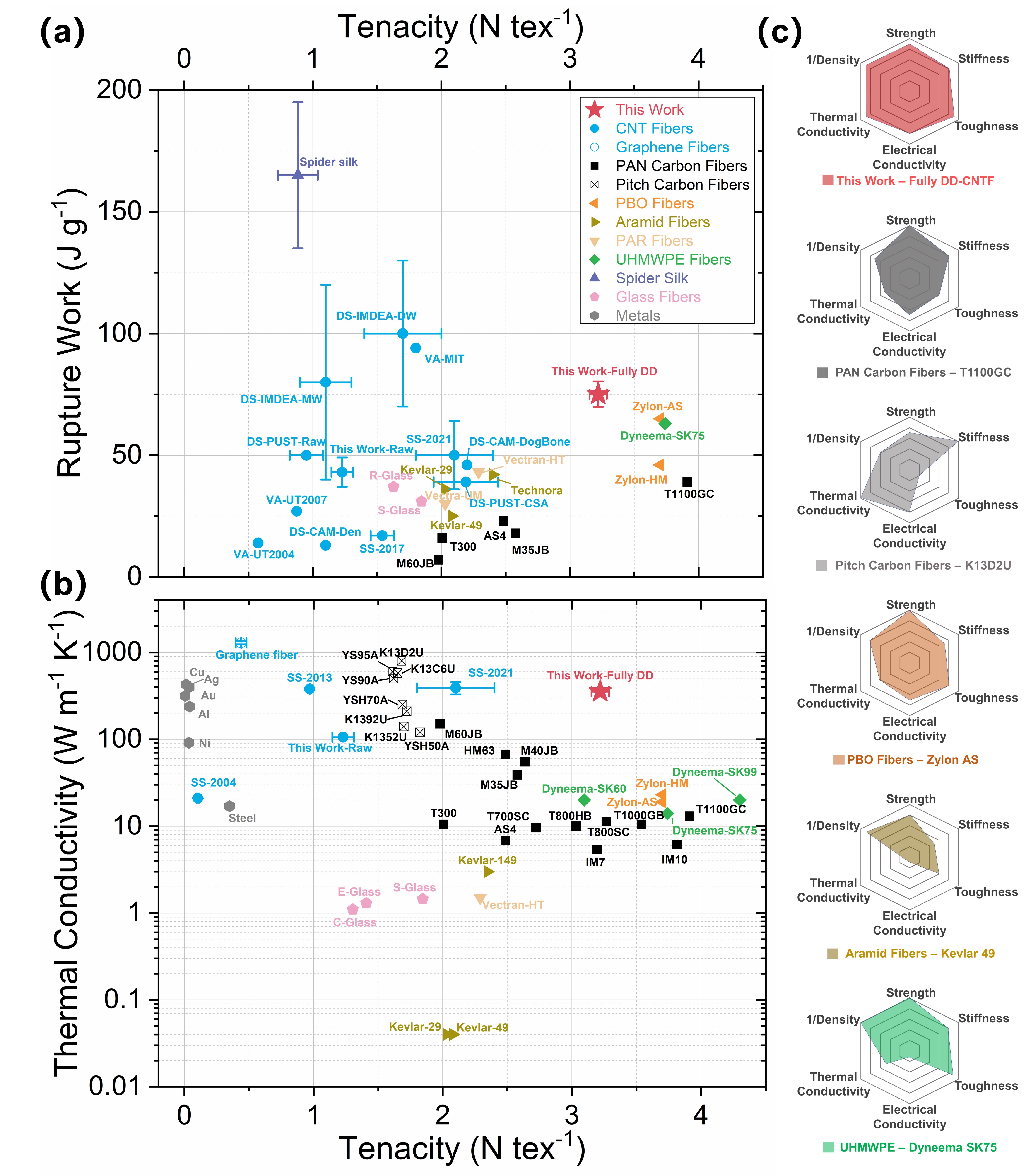
As shown in Fig.6, compared with current leading fibers, carbon nanotube fibers can exhibit overall versatile performance with a combination of high specific tensile strength (tenacity), work of rupture, thermal conductivity, and specific volume (e.g. low density). The fully DD-CNTFs have thermal conductivities that match the best pitch-based CFs and surpass them in terms of tenacity and ductility. The fully DD-CNTF tenacity is within 15% of the strongest PAN-based CFs (T1000GB) and PBO fibers (Zylon AS and HM), while tougher and more conductive. The performance of fully DD-CNTFs are superior to Kevlar for all reported metrics highlighting potential applications of impact shielding or advanced structural usage with thermal management purposes.
The DD-CNTFs further the trend of the remarkable annual improvements of CNTF properties highlighted by Taylor et al over the last decade.Taylor2021 The DD-CNTFs is a method that enhances commercially-produced raw fibers with fiber test lengths (10-20 mm) from medium-grade crystalline materials (, Fig.S7). When compared to congeneric fibers, including the solution-spun CNTF composed of higher crystallinity CNTs (),Taylor2021 the fully DD-CNTF have improved strength and modulus, owing to the longer effective length of CNTs. Compared to other CNTF acid stretching processes, the DD-CNTF enables a larger while improving the overall fiber properties. Short CNT strand (VA-MIT) have higher work of rupture than DD-CNTFs (), but compromise strength and modulus with short fibers that were restricted lengths less than the individual CNTs ().Hill2013 Critically, the present work enables sustained strength over gauge lengths that exceed the longest CNTs and offer a measure of scaled fiber performance that is comparable (0-25% less) to high work of rupture of the IMDEA materials. Our materials do not require removal of catalyst or other impurities from CNTFs which account for with marginally crystalline material.
3 Discussions
3.1 Load Transfer Efficiency on Individual Tubes As Illustrated by the In-Situ Stretching Raman

The distinctive increase in mechanical properties after the Double-Drawing process warrants a mechanistic study of the enhancing mechanisms to determine whether the DD-CNTFs have taken the full advantage of iCNTs’ properties. Here we use the In-Situ Stretching Raman (ISSR) with the polarized detecting configuration to study the load transfer efficiency on iCNTs. In contrast to the common polarized Raman characterization that solely depicts the CNTs alignment in fibers, ISSR enables assessment of the distribution of strain on iCNTs.Chang2010 In ISSR, the C-C bonds softens under stretching, redshifting the Raman G’ mode proportionally with strain.Cronin2004 ; Mohiuddin2009
It is important to note that the ISSR spectrum is an amalgamation of every section on thousands of iCNTs within the laser spot, which can experience various strain. Along each CNT the strain can be distributed unevenly. Based on the antenna effect of CNTs,Saito2011 ; Zhang2015b we use ZZ/XX polarization configuration to detect the strain distribution of iCNTs parallel/perpendicular to the axis of CNTF (Fig.7a). As shown in Fig.7b, when CNTF strain () is gradually increased, sections in the spectrum start to redshift differently (red and blue dotted lines), from which the corresponding strain distribution among iCNTs () can thus be deduced (more details can be found in S4). To highlight the evolution of with corresponding , we accumulate these spectra of each CNTF into its contour plot (Fig.7c-h). As the fiber strain increases to =1.27% (Zone i) the tubes parallel to the raw CNTF axis (ZZ configuration, Fig.7c) exhibit a small broadening in the spectrum tail of low-frequency (white solid arrow), while the middle and high frequency sections change little (white dotted arrow). This implies that only a small proportion of CNTs share the strain on the fiber, while the others do not participate.Cronin2005 ; Kumar2007 ) When =1.27% the average can be deduced (calculation details can be found in S4). We use load transfer ratio as a figure of merit for load sharing. Thus, the average () is only , which indicates that the fiber strain is primarily a result of straightening of curled tubes, alignment of tubes towards axis direction or the relative slippage among tubes, rather than the strain increase on iCNTs. For larger strain, , the redshift reaches a plateau without any changes in the spectrum (Zone ii). does not further increase and reaches a maximum, (the corresponding is ), indicating the occurrence of slippage between iCNTs. Approaching the failure point (, Zone iii), the broadening disappears (short white dotted arrows), which indicates the remaining small portion of CNTs break and return to the initial state without any strain.
As a comparison, the fully DD-CNTF (Fig.7e) shows a significant enhancement on the load sharing on the iCNTs. As load increases to =0.97%, the entire peak of G’ mode redshifts without obvious broadening (white dotted arrow vs white solid arrow), which we referred as Zone i’. The corresponding increases to at =0.97%. The redshift of the entire G’ mode indicates that a major portion of CNTs take the load with fiber. More importantly, with greater strain, , there is no plateau of redshift in Zone ii’. Instead, the spectrum splits into 2 groups: one group (indicated by the red arrow) continues to share the load as increases, while the other group (indicated by the blue arrow) gradually releases when strained, indicating the successive failure of thick bundles. For the former group, continues to increase and finally achieves just before the rupture of CNTF, The corresponding can then be deduced as high as 0.89, indicating that a portion of CNTs synchronize with the fiber to take the load from the beginning until the fracture. We did not observe the Zone iii strain releases to the initial state as occurred with the raw CNTF.
For the moderate DD-CNTF ( and , Fig.7d), its behavior falls in between raw CNTF and fully DD-CNTF. The at the end of Zone i is . Like the fully DD-CNTF, Zone ii’ appears with increases. finally reaches just before the rupture of CNTF. The corresponding is . Without the Poisson Tightening process, the fully SD-CNTF behaves similarly in Zone i’ and ii’ (Fig.7g), with at the end of Zone i’, and is when . Importantly, in the Zone iii where approaches the rupture point, cannot further increase, while the other portion of CNTs release to the initial state free of strain. As a contrast, for the tubes perpendicular to the fiber axis (XX-Polarization), for both raw (Fig.7f) and the fully DD-CNTFs (Fig.7h), during the whole period, changes very little with the increase of , indicating the redundance of tubes perpendicular to the axis.
Collectively the ISSR results for CNTFs with different enhancing process, enables insights into CNTFs and the Double-Drawing process, namely (1) only a small portion of CNTs in the raw CNTF can take axial load; (2) with only small strain on iCNTs, slippage will happen in raw CNTF; (3) by drawing in CSA, a larger portion of CNTs can participate in load sharing upon initial loading; (4) by drawing in CSA, higher strain on iCNTs are needed to lead to a slippage; (5) Poisson Tightening can further increase the strain capacity on iCNTs. The cumulative impact of these optimization from the Double-Drawing elucidates the substantial increase in the breaking tenacity of the fully DD-CNTF.
3.2 Enhancing Mechanism - the Increase of Effective Bundles and the Extension of CNTs Effective Length in Bundle
The improvement of properties after the saturation of alignment optimization, and the ever rising of and after processing, indicates additional factors must be included to develop a representative mechanism for CNTF loading. Misorientation of monomer units along the polymer chain has been recognized as the primary factor that leads to the reduction of stiffness of many synthetic fibers.Adams1987 The tensile Young’s modulus of fibers is commonly estimated by the appropriate average of the moduli of all monomers along the axis.Hearle2008 However, the assumption implies that all monomers evenly participate within a fiber, which is not suitable for a fibrillar assembly like the CNTF. The movement and deformation of iCNTs within CNTFs are not all affine. Instead under load a tensioning line frequently appears from the disordered network in raw CNTFs, which indicates the stress concentration, also the only portion of CNTs bearing the load (detailed analysis can be found in S5).
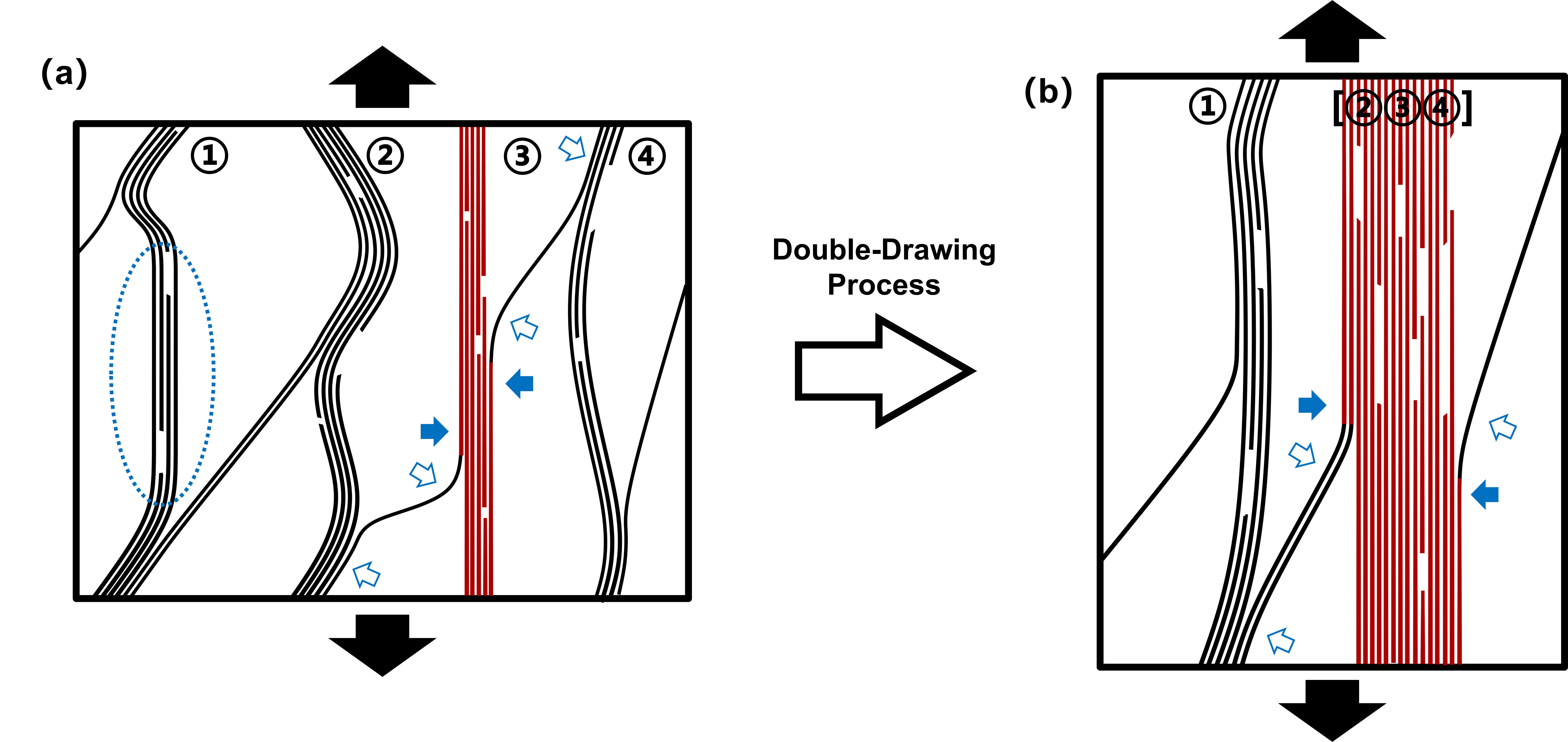
As shown within a simplified CNTF cell (Fig.8a), if the load is exerted on the vertical surfaces of the cell (along axis), there is no medium between CNTs to transmit the load, thus only the shortest CNT bundle is loaded (bundle ③, the red lines). While alignment analysis by WAXD shows a substantial alignment, the portion of idle CNTs cannot be determined. Therefore, for the fibrillar structures the straightening of bundles is a more indicative metric for fiber strength than orientation factor. After the drawing in CSA, more crumpled tubes and bundles straighten ([②③④]) and become effective to link the “shortest” distance (the red lines in Fig.8b). They jointly participate in sharing the load after the initial stretching. More correlations between this factor to the optimization of ISSR results and mechanical properties can be found in S5.
Nevertheless, only accounting for the increased fraction of load-bearing bundles in network does not fully explain the much higher for the DD-CNTF. As the appears immediately prior to failure, the much-improved tenacity for the fully DD-CNTF must therefore be considered. For the elastic interface (static friction), the stress exerted on iCNTs , is balanced by the friction from the surrounding tubes, where and is the tube’s Young’s modulus and strain, respectively.Gupta2020 When increases to the critical value , slippage will occur and the elastic interface will begin to deform plasticly. Immediately prior to slippage, , where is the cross-sectional area of the tube, is tube’s maximum static friction coefficient per unit length, and is the effective length of tube that shares the load (friction). Thus, is the maximum value for and the corresponding can be deduced by:
| (1) |
In a fibrillar structure, particularly raw CNTF (entire length of iCNTs Mikhalchan2019 ), tubes within the hierarchical network only partly align with any specific bundle, and may be incorporated into many bundles. Because the load can only be transmitted through the coupling between adjacent tubes, only the tube section attached to an effective bundle can participate in sharing the load (the red lines as indicated by solid blue arrows in Fig.8), i.e., (Fig.1b-c). With the Double-Drawing process, longer length of tubes aggregate into the effective bundles ([②③④] in Fig.8b), with approaching . Consequently, needed to activate the slippage also increases, which delays the failure of DD-CNTF and improves the tenacity (discussed further in S5).
Although the conduction pathway for heat is not essential to be shortest, the thermal conduction benefits when more bundles and larger fraction of tubes become effective. The junction boundaries between bundles are likely a first order contribution to thermal resistance,Chalopin2009 which become sparser along the fiber axis after the Double-Drawing. With the increase of and alignment of adjoining bundles, the joint length and interfacial area between tubes are extended, improving the thermal conductance through the corresponding junctions.
4 Conclusions
In summary, we have developed a technique to enhance CNT fibers by successively drawing the raw direct-spun CNTFs within CSA and chloroform at ambient temperature and pressure, which aligns the CNT bundles, densifies the fibers and removes the residue CSA via Poisson Tightening and rinsing. With full Double-Drawing, CNTFs reach a tenacity of (4.60 GPa), Young’s modulus of , rupture work of , electrical conductivity of , and thermal conductivity of . The resulting simultaneous optimization properties results in an attractive overall performance, continuing the impressive line of improvement seen within CNTFs worldwide in recent years. We anticipate further advancement in material properties using the Double-Drawing technique which is applicable to other CNTs ensemble including forests, films, fibers, and aerogels.
Importantly, in addition to the known dependence of properties on CNT alignment and stacking, new evidence of the load transfer coefficient on individual CNTs highlights the importance of (i) straightening of CNT bundles which increases the proportion of effective bundles jointly sharing the load and (ii) the higher barrier of slippage activation within bundles, which originates from the effective tube length increase within effective bundles.
The comprehensive improvement of CNTF properties enables long-sought applications of advanced load-bearing fibers that can simultaneously dissipate heat, shield impacts, or dissipate electrical charge. Comprehensive understanding, advancement of these multitude of mechanisms, and resulting properties are necessary to manifest bulk CNT fiber properties that approach the horizon of properties offered by individual CNTs.
5 Experimental/Methods Section
CNT fibers preparation: Continuous CNTFs were fabricated using the floating catalyst method,Li2004 ; Motta2007a and supplied by Tortech Nanofibers Ltd. The produced CNT aerogels from a tube furnace were mechanically pulled out, densified by acetone, and spun continuously winded. Although a small tension force is applied during the spinning process to obtain a preferential alignment along fiber axis, the anisotropic ratio is always within 0.85.Zhang2018
Enhancing CNTF with the Double-Drawing process: (i) Immersing and first drawing: The raw CNTF is fixed at its lower end inside a dropping funnel, and its upper end fixed on a spin rotor. The CNTF is straightened out but without a pre-tension. After being immersed in chlorosulfonic acid (CSA), CNTF is firstly drawn to a specific ratio (; (ii) Poisson Tightening: After the immersing solvent being changed into chloroform, the CNTF is immediately further drawn by . (iii) Rinsing: after the Double-Drawing processes, the CNTF is successively rinsed in water and acetone, and finally vacuum dried.
Linear Density measurement: The is measured based on Direct Single-fiber Weight Determination, following ASTM D1577-07(2018) OPTION B. The weight of a CNTF with length is measured with a Sartorius SE2 Ultra-micro balance. We find it worthy to notice the importance of accurately measurement of , because the susceptibility of fiber’s tenacity to . The frequently used Vibroscopic method in reports is abandoned here, because of the potential serious underestimation of , if the “stiffness correction” was overlooked (ASTM D1577-07(2018) OPTION C - the standard for the Vibroscopic method). More discussion can be found in S2.
Tensile test: The CNTFs are tested with the Single-Fiber Testers (Textechno FAVIMAT with Load cell of 210 cN and delicately aligned clamps ( hard rubber), the force resolution of , the displacement resolution of ). The CNTFs are tested with gauge length of , stretching speed of 1 mm min-1 and pretension of . Every sample is tested for 3 specimens to guarantee the repeatability of results. Stretching speeds of 0.2, 2 and 5 , and gauge length of have been tried to generate similar results.
Thermal and Electrical conductivity measurement: The thermal conductivity of CNTF along fiber axis is performed with a homemade measuring apparatus based on a self-heating method.Zhou2017 The electrical conductivity of CNTFs along fiber axis is measured in air at room temperature (1 atm, C, relative humidity: ) by a homemade testing stage using the four-electrode method and steady-state method.Zhou2016
In-Situ Stretching Raman: The suspended CNTFs are ends fixed onto a manual stretching stage to detect the Raman signal with HORIBA HR800 micro-Raman spectroscopy. We excite the Raman G’ mode with linearly polarized laser, and only collect the scattered radiation in the parallel polarization with a Glan Polarizer, so that only iCNTs with their axis close to parallel with the laser polarization can be detected. For the ZZ/XX configuration,Damnjanovic1999 the polarizations of both incident and scattered photons are parallel/perpendicular to the axis of CNTFs, offering the strain distribution of CNTs along/normal to the fiber axis;
Wide Angle X-ray Diffraction (WAXD)/Small-Angle X-ray Scattering (SAXS): The CNTFs with different processing are studied using a small and wide-angle diffractometer (Molecular Metrology SAXS system) equipped with a sealed microfocus tube (MicroMax-002+S) emitting Cu radiation (wavelength of ), two Göbel mirrors, and three pinhole slits. CNTFs with diameter of were suspended onto a holder perpendicular to the beam and measured at ambient temperature. All the raw data are analyzed by SAXSGUI. For data analysis of WAXD, the sharp equatorial reflections at corresponding to the scattering from (002) reflection of the inter-layer spacing of a few walled CNT, and to a higher order reflection of the hexagonal packing of parallel CNTs. Both possibilities are due to the planes perpendicular to the CNT axis. To obtain the azimuthal profile of (002) scattering, the intensity is integrated in the range of . With the increase of the alignment, two peaks emerge in the azimuthal profile around the preferred alignment, from which the Full Width Half Maximum is obtained. For data analysis of SAXS, the integrating range is to obtain the azimuthal profile of scattering.
Other characterization: The cross-sections of CNTFs are fabricated with FIB (FEI Helios 600i). The cross-section is firstly cut with Gallium ions with current of 9 nA (30 kV) and then finely polished under current of 0.79 nA, after which the SEM of cross-sections are conducted by electron beam of FIB. The SEM for other CNTFs is conducted on a TESCAN MIRA3. HRTEM is conducted on an FEI Talos F200X TEM working under 80 kV to reduce the damage to CNTs.
Supplementary materials
Supplementary materials are available.
Acknowledgements Funding: This work is supported by EPSRC project ’Advanced Nanotube Application and Manufacturing (ANAM) Initiative’ [grant numbers: EP/M015211/1]. WY Zhou and HP Liu thank the partial support by the National Key R&D Program of China [grant numbers: 2018YFA0208402, 2020YFA0714700]. General: The authors especially thank Ms. Mingzhao Wang, Prof. Wei Tan, Dr. Joe Stallard, Dr. Le Cai, Ms Rulan Qiao, Dr. Sarah Stevenson, for their kind support and useful discussion. The author also thanks Dr. Heather Greer, Dr. Rafail Khalfin, Prof. Yachin Cohen, and Prof. Thurid S. Gspann for TEM, WAXD, SAXS, and mechanical experiment support. Competing interests: All authors declare that they have no competing interests. Data and materials availability: All data needed to evaluate the conclusions in the paper are present in the paper and/or the Supplementary Materials. Additional data related to this paper may be requested from the authors. Author Contributions: Conceptualization: XZ, MDV, SSX, AMB; Methodology: XZ, MDV, WBZ; Formal analysis: XZ, WBZ, AMB; Investigation: XZ, WBZ, JTP, AK; Resources: WBZ, LI, AK, JTP, FRS, ZBW, JAE; Validation: MDV, WBZ, WYZ, JAE, AMB; Supervision: MDV, HPL, WYZ, SSX, AMB; Project administration: YCW, AMB; Funding acquisition: HPL, WYZ, AMB; Writing—original draft: XZ, MDV, AMB; Writing—review & editing: XZ, MDV, WBZ, XJW, JTP, HPL, WYZ, JAE, AMB.
References
- \bibcommenthead
- (1) Fakhri, N., Tsyboulski, D.A., Cognet, L., Bruce Weisman, R., Pasquali, M.: Diameter-dependent bending dynamics of single-walled carbon nanotubes in liquids. Proceedings of the National Academy of Sciences of the United States of America 106(34), 14219–14223 (2009). https://doi.org/10.1073/pnas.0904148106
- (2) Mikhalchan, A., Vilatela, J.J.: A perspective on high-performance CNT fibres for structural composites. Carbon 150, 191–215 (2019). https://doi.org/10.1016/j.carbon.2019.04.113
- (3) Min-Feng, Y., Oleg, L., J., D.M., Katerina, M., F., K.T., S., R.R.: Strength and Breaking Mechanism of Multiwalled Carbon Nanotubes Under Tensile Load. Science 287(5453), 637–640 (2000). https://doi.org/10.1126/science.287.5453.637
- (4) Peng, B., Locascio, M., Zapol, P., Li, S., Mielke, S.L., Schatz, G.C., Espinosa, H.D.: Measurements of near-ultimate strength for multiwalled carbon nanotubes and irradiation-induced crosslinking improvements. Nature Nanotechnology 3(10), 626–631 (2008). https://doi.org/10.1038/nnano.2008.211
- (5) Zhang, X., Lu, W., Zhou, G., Li, Q.: Understanding the Mechanical and Conductive Properties of Carbon Nanotube Fibers for Smart Electronics (2020). https://doi.org/10.1002/adma.201902028
- (6) Kim, P., Shi, L., Majumdar, A., McEuen, P.L.: Thermal transport measurements of individual multiwalled nanotubes. Physical Review Letters 87(21), 215502 (2001) arXiv:0106578 [cond-mat]. https://doi.org/10.1103/PhysRevLett.87.215502
- (7) Pop, E., Mann, D., Wang, Q., Goodson, K.E., Dai, H.J.: Thermal conductance of an individual single-wall carbon nanotube above room temperature. Nano Letters 6(1), 96–100 (2006). https://doi.org/10.1021/Nl052145f
- (8) Bulmer, J.S., Kaniyoor, A., Elliott, J.A.: A Meta-Analysis of Conductive and Strong Carbon Nanotube Materials. Advanced Materials n/a(n/a), 2008432 (2021). https://doi.org/10.1002/adma.202008432
- (9) Komatsu, N., Ichinose, Y., Dewey, O.S., Taylor, L.W., Trafford, M.A., Yomogida, Y., Wehmeyer, G., Pasquali, M., Yanagi, K., Kono, J.: Macroscopic weavable fibers of carbon nanotubes with giant thermoelectric power factor. Nature Communications 12(1), 4931 (2021). https://doi.org/10.1038/s41467-021-25208-z
- (10) De Volder, M.F.L.L., Tawfick, S.H., Baughman, R.H., Hart, A.J.: Carbon Nanotubes: Present and Future Commercial Applications. Science 339(6119), 535–539 (2013). https://doi.org/10.1126/science.1222453
- (11) Tombler, T.W., Zhou, C., Alexseyev, L., Kong, J., Dai, H., Liu, L., Jayanthi, C.S., Tang, M., Wu, S.-Y.: Reversible electromechanical characteristics of carbon nanotubes underlocal-probe manipulation. Nature 405(6788), 769–772 (2000). https://doi.org/10.1038/35015519
- (12) Yu, M.-F., Files, B.S., Arepalli, S., Ruoff, R.S.: Tensile Loading of Ropes of Single Wall Carbon Nanotubes and their Mechanical Properties. Physical Review Letters 84(24), 5552–5555 (2000). https://doi.org/10.1103/PhysRevLett.84.5552
- (13) Baughman, H.R., Zakhidov, A.A., de Heer Walt, A.: Carbon Nanotubes–the Route Toward Applications. Science 297(5582), 787–792 (2002). https://doi.org/10.1126/science.1060928
- (14) Bai, Y., Zhang, R., Ye, X., Zhu, Z., Xie, H., Shen, B., Cai, D., Liu, B., Zhang, C., Jia, Z., Zhang, S., Li, X., Wei, F.: Carbon nanotube bundles with tensile strength over 80 GPa. Nature Nanotechnology 13(7), 589–595 (2018). https://doi.org/10.1038/s41565-018-0141-z
- (15) Koziol, K., Vilatela, J., Moisala, A., Motta, M., Cunniff, P., Sennett, M., Windle, A.: High-performance carbon nanotube fiber. Science 318(5858), 1892–1895 (2007). https://doi.org/10.1126/science.1147635
- (16) Fernández-Toribio, J.C., Alemán, B., Ridruejo, Á., Vilatela, J.J.: Tensile properties of carbon nanotube fibres described by the fibrillar crystallite model. Carbon 133, 44–52 (2018). https://doi.org/10.1016/j.carbon.2018.03.006
- (17) Wang, J.N., Luo, X.G., Wu, T., Chen, Y.: High-strength carbon nanotube fibre-like ribbon with high ductility and high electrical conductivity. Nature Communications 5(1), 3848 (2014). https://doi.org/10.1038/ncomms4848
- (18) Tran, T.Q., Fan, Z., Liu, P., Myint, S.M., Duong, H.M.: Super-strong and highly conductive carbon nanotube ribbons from post-treatment methods. Carbon 99, 407–415 (2016). https://doi.org/10.1016/j.carbon.2015.12.048
- (19) Xu, W., Chen, Y., Zhan, H., Wang, J.N.: High-Strength Carbon Nanotube Film from Improving Alignment and Densification. Nano Letters 16(2), 946–952 (2016). https://doi.org/10.1021/acs.nanolett.5b03863
- (20) Zhang, M., Atkinson, K.R., Baughman, R.H.: Multifunctional carbon nanotube yarns by downsizing an ancient technology. Science 306(5700), 1358–1361 (2004). https://doi.org/10.1126/science.1104276
- (21) Headrick, R.J., Tsentalovich, D.E., Berdegué, J., Bengio, E.A., Liberman, L., Kleinerman, O., Lucas, M.S., Talmon, Y., Pasquali, M.: Structure–Property Relations in Carbon Nanotube Fibers by Downscaling Solution Processing. Advanced Materials 30(9), 1–8 (2018). https://doi.org/10.1002/adma.201704482
- (22) Behabtu, N., Young, C.C., Tsentalovich, D.E., Kleinerman, O., Wang, X., Ma, A.W.K., Bengio, E.A., Ter Waarbeek, R.F., De Jong, J.J., Hoogerwerf, R.E., Fairchild, S.B., Ferguson, J.B., Maruyama, B., Kono, J., Talmon, Y., Cohen, Y., Otto, M.J., Pasquali, M.: Strong, light, multifunctional fibers of carbon nanotubes with ultrahigh conductivity. Science 339(6116), 182–186 (2013). https://doi.org/10.1126/science.1228061
- (23) Lee, J., Lee, D.M., Jung, Y., Park, J., Lee, H.S., Kim, Y.K., Park, C.R., Jeong, H.S., Kim, S.M.: Direct spinning and densification method for high-performance carbon nanotube fibers. Nature Communications 10(1), 1–10 (2019). https://doi.org/10.1038/s41467-019-10998-0
- (24) Davis, V.A., Parra-Vasquez, A.N.G., Green, M.J., Rai, P.K., Behabtu, N., Prieto, V., Booker, R.D., Schmidt, J., Kesselman, E., Zhou, W., Fan, H., Adams, W.W., Hauge, R.H., Fischer, J.E., Cohen, Y., Talmon, Y., Smalley, R.E., Pasquali, M.: True solutions of single-walled carbon nanotubes for assembly into macroscopic materials. Nature Nanotechnology 4(12), 830–834 (2009). https://doi.org/10.1038/nnano.2009.302
- (25) Parra-Vasquez, A.N.G., Behabtu, N., Green, M.J., Pint, C.L., Young, C.C., Schmidt, J., Kesselman, E., Goyal, A., Ajayan, P.M., Cohen, Y., Talmon, Y., Hauge, R.H., Pasquali, M.: Spontaneous dissolution of ultralong single-and multiwalled carbon nanotubes. ACS Nano 4(7), 3969–3978 (2010). https://doi.org/10.1021/nn100864v
- (26) Ramesh, S., Ericson, L.M., Davis, V.A., Saini, R.K., Kittrell, C., Pasquali, M., Billups, W.E., Adams, W.W., Hauge, R.H., Smalley, R.E.: Dissolution of Pristine Single Walled Carbon Nanotubes in Superacids by Direct Protonation. The Journal of Physical Chemistry B 108(26), 8794–8798 (2004). Chap. 8794. https://doi.org/10.1021/jp036971t
- (27) Hearle, J.W.S., Morton, W.E.: Physical Properties of Textile Fibres. Elsevier, ??? (2008)
- (28) Lee, D.-M., Park, J., Lee, J., Lee, S.-H., Kim, S.-H., Kim, S.M., Jeong, H.S.: Improving Mechanical and Physical Properties of Ultra-thick Carbon Nanotube Fiber by Fast Swelling and Stretching Process. Carbon (2020). https://doi.org/10.1016/j.carbon.2020.10.068
- (29) Aliev, A.E., Lima, M.H., Silverman, E.M., Baughman, R.H.: Thermal conductivity of multi-walled carbon nanotube sheets: Radiation losses and quenching of phonon modes. Nanotechnology 21(3) (2010). https://doi.org/10.1088/0957-4484/21/3/035709
- (30) Boies, A.M., Hoecker, C., Bhalerao, A., Kateris, N., de La Verpilliere, J., Graves, B., Smail, F.: Agglomeration Dynamics of 1D Materials: Gas-Phase Collision Rates of Nanotubes and Nanorods. Small 15(27), 1900520 (2019). https://doi.org/10.1002/smll.201900520
- (31) Kateris, N., Kloza, P., Qiao, R., Elliott, J.A., Boies, A.M.: From Collisions to Bundles: An Adaptive Coarse-Grained Model for the Aggregation of High-Aspect-Ratio Carbon Nanotubes. The Journal of Physical Chemistry C 124(15), 8359–8370 (2020). https://doi.org/10.1021/acs.jpcc.9b10479
- (32) Yakobson, B.I., Couchman, L.S.: Persistence Length and Nanomechanics of Random Bundles of Nanotubes. Journal of Nanoparticle Research 8(1), 105–110 (2006). https://doi.org/10.1007/s11051-005-8335-3
- (33) Bedewy, M., Meshot, E.R., Guo, H., Verploegen, E.A., Lu, W., Hart, A.J.: Collective Mechanism for the Evolution and Self-Termination of Vertically Aligned Carbon Nanotube Growth. The Journal of Physical Chemistry C 113(48), 20576–20582 (2009). https://doi.org/%****␣main-text.bbl␣Line␣675␣****10.1021/jp904152v
- (34) Kaniyoor, A., Gspann, T.S., Mizen, J.E., Elliott, J.A.: Quantifying alignment in carbon nanotube yarns and similar two-dimensional anisotropic systems. Journal of Applied Polymer Science 138(37), 50939 (2021). https://doi.org/10.1002/app.50939
- (35) Stallard, J.C., Tan, W., Smail, F.R., Gspann, T.S., Boies, A.M., Fleck, N.A.: The mechanical and electrical properties of direct-spun carbon nanotube mats. Extreme Mechanics Letters 21, 65–75 (2018). https://doi.org/10.1016/j.eml.2018.03.003
- (36) Park, J., Lee, J., Lee, D.-M., Lee, S.-H., Jeong, H.S., Lee, K.-H., Kim, S.M.: Mathematical model for the dynamic mechanical behavior of carbon nanotube yarn in analogy with hierarchically structured bio-materials. Carbon 152, 151–158 (2019). https://doi.org/10.1016/j.carbon.2019.05.077
- (37) Prasher, R.S., Hu, X.J., Chalopin, Y., Mingo, N., Lofgreen, K., Volz, S., Cleri, F., Keblinski, P.: Turning Carbon Nanotubes from Exceptional Heat Conductors into Insulators. Physical Review Letters 102(10), 105901 (2009). https://doi.org/10.1103/PhysRevLett.102.105901
- (38) Dresselhaus, M.S., Eklund, P.C.: Phonons in carbon nanotubes. Advances in Physics 49(6), 705–814 (2000). https://doi.org/10.1080/000187300413184
- (39) Taylor, L.W., Dewey, O.S., Headrick, R.J., Komatsu, N., Peraca, N.M., Wehmeyer, G., Kono, J., Pasquali, M.: Improved properties, increased production, and the path to broad adoption of carbon nanotube fibers. Carbon 171, 689–694 (2021). https://doi.org/10.1016/j.carbon.2020.07.058
- (40) Hill, F.A., Havel, T.F., Hart, A.J., Livermore, C.: Enhancing the Tensile Properties of Continuous Millimeter-Scale Carbon Nanotube Fibers by Densification. ACS Applied Materials & Interfaces 5(15), 7198–7207 (2013). https://doi.org/10.1021/am401524q
- (41) Chang, C.-C., Hsu, I.-K., Aykol, M., Hung, W.-H., Chen, C.-C., Cronin, S.B.: A New Lower Limit for the Ultimate Breaking Strain of Carbon Nanotubes. ACS Nano 4(9), 5095–5100 (2010). https://doi.org/10.1021/nn100946q
- (42) Cronin, S.B., Swan, A.K., Ünlü, M.S., Goldberg, B.B., Dresselhaus, M.S., Tinkham, M.: Measuring the Uniaxial Strain of Individual Single-Wall Carbon Nanotubes: Resonance Raman Spectra of Atomic-Force-Microscope Modified Single-Wall Nanotubes. Physical Review Letters 93(16), 167401 (2004). https://doi.org/10.1103/PhysRevLett.93.167401
- (43) Mohiuddin, T.M.G., Lombardo, A., Nair, R.R., Bonetti, A., Savini, G., Jalil, R., Bonini, N., Basko, D.M., Galiotis, C., Marzari, N., Novoselov, K.S., Geim, A.K., Ferrari, A.C.: Uniaxial strain in graphene by Raman spectroscopy: G peak splitting, Gruneisen parameters, and sample orientation. Physical Review B 79(20), 205433 (2009). https://doi.org/10.1103/PhysRevB.79.205433
- (44) Saito, R., Hofmann, M., Dresselhaus, G., Jorio, A., Dresselhaus, M.S.: Raman spectroscopy of graphene and carbon nanotubes. Advances in Physics 60(3), 413–550 (2011). https://doi.org/10.1080/00018732.2011.582251
- (45) Zhang, X., Song, L., Cai, L., Tian, X., Zhang, Q., Qi, X., Zhou, W., Zhang, N., Yang, F., Fan, Q., Wang, Y., Liu, H., Bai, X., Zhou, W., Xie, S.: Optical visualization and polarized light absorption of the single-wall carbon nanotube to verify intrinsic thermal applications. Light: Science and Applications 4(8) (2015). https://doi.org/10.1038/lsa.2015.91
- (46) Cronin, S.B., Swan, A.K., Ünlü, M.S., Goldberg, B.B., Dresselhaus, M.S., Tinkham, M.: Resonant Raman spectroscopy of individual metallic and semiconducting single-wall carbon nanotubes under uniaxial strain. Physical Review B 72(3), 35425 (2005). https://doi.org/10.1103/PhysRevB.72.035425
- (47) Kumar, R., Cronin, S.B.: Raman scattering of carbon nanotube bundles under axial strain and strain-induced debundling. Physical Review B 75(15), 155421 (2007). https://doi.org/10.1103/PhysRevB.75.155421
- (48) Adams, W.W., Eby, R.K.: High-Performance Polymer Fibers. MRS Bulletin 12(8), 22–26 (1987). https://doi.org/10.1557/S0883769400066707
- (49) Gupta, N., Alred, J.M., Penev, E.S., Yakobson, B.I.: Universal strength scaling in carbon nanotube bundles with frictional load transfer. ACS Nano 15(1), 1342–1350 (2020). https://doi.org/10.1021/acsnano.0c08588
- (50) Chalopin, Y., Volz, S., Mingo, N.: Upper bound to the thermal conductivity of carbon nanotube pellets. Journal of Applied Physics 105(8), 84301 (2009). https://doi.org/10.1063/1.3088924
- (51) Li, Y.L., Kinloch, I.A., Windle, A.H.: Direct Spinning of Carbon Nanotube Fibers from Chemical Vapor Deposition Synthesis. Science 304(5668), 276–278 (2004). https://doi.org/10.1126/science.1094982
- (52) Motta, M., Moisala, A., Kinloch, I.A., Windle, A.H.: High performance fibres from ’dog bone’ carbon nanotubes. Advanced Materials 19(21), 3721–3726 (2007). https://doi.org/%****␣main-text.bbl␣Line␣1025␣****10.1002/adma.200700516
- (53) Zhang, X., Tan, W., Smail, F., De Volder, M., Fleck, N., Boies, A.: High-fidelity characterization on anisotropic thermal conductivity of carbon nanotube sheets and on their effects of thermal enhancement of nanocomposites. Nanotechnology 29(36), 365708 (2018). https://doi.org/10.1088/1361-6528/aacd7b
- (54) Zhou, W., Fan, Q., Zhang, Q., Cai, L., Li, K., Gu, X., Yang, F., Zhang, N., Wang, Y., Liu, H., Zhou, W., Xie, S.: High-performance and compact-designed flexible thermoelectric modules enabled by a reticulate carbon nanotube architecture. Nature Communications 8(1), 14886 (2017). https://doi.org/10.1038/ncomms14886
- (55) Zhou, W.B., Fan, Q.X., Zhang, Q., Li, K.W., Cai, L., Gu, X.G., Yang, F., Zhang, N., Xiao, Z.J., Chen, H.L., Xiao, S.Q., Wang, Y.C., Liu, H.P., Zhou, W.Y., Xie, S.S.: Ultrahigh-Power-Factor Carbon Nanotubes and an Ingenious Strategy for Thermoelectric Performance Evaluation. Small 12(25), 3407 (2016). https://doi.org/10.1002/smll.201600501
- (56) Damnjanović, M., Milošević, I., Vuković, T., Sredanović, R.: Full symmetry, optical activity, and potentials of single-wall and multiwall nanotubes. Physical Review B 60(4), 2728–2739 (1999). https://doi.org/10.1103/PhysRevB.60.2728