Efficient scheme for realizing a multiplex-controlled phase gate with photonic qubits in circuit quantum electrodynamics
Abstract
We propose an efficient scheme to implement a multiplex-controlled phase
gate with multiple photonic qubits simultaneously controlling one target
photonic qubit based on circuit quantum electrodynamics (QED). For convenience, we denote this
multiqubit gate as MCP gate. The gate is realized by using a two-level
coupler to couple multiple cavities. The coupler here is a superconducting
qubit. This scheme is simple because the gate implementation requires only one step of operation. In addition, this scheme is quite general because the two logic states of each photonic qubit can be encoded with a
vacuum state and an arbitrary non-vacuum state (e.g., a Fock state, a superposition of Fock states, a cat
state, or a coherent state, etc.) which is orthogonal or quasi-orthogonal to
the vacuum state. The scheme has some additional advantages: Because only
two levels of the coupler are used, i.e., no auxiliary levels are utilized,
decoherence from higher energy levels of the coupler is avoided; the gate
operation time does not depend on the number of qubits; and the gate is
implemented deterministically because no measurement is applied. As an
example, we numerically analyze the circuit-QED based experimental
feasibility of implementing a three-qubit MCP gate with photonic qubits each
encoded via a vacuum state and a cat state. The scheme can be applied to
accomplish the same task in a wide range of physical system, which consists
of multiple microwave or optical cavities coupled to a two-level coupler
such as a natural or artificial atom.
Keywords multiplex controlled, phase gate, circuit QED
I Introduction and motivation
Multiqubit gates (i.e., -qubit gates with ) are essential elements in quantum networks, quantum simulation, and quantum information processing (QIP). Generally speaking, there are two types of significant multiqubit gates, which have drawn much attention during the past years. One is a multiplex-controlled NOT or phase gate with multiple qubits simultaneously controlling one target qubit (Fig. 1). The other is a multi-target-qubit controlled NOT or phase gate with one qubit simultaneously controlling multiple target qubits (Fig. 2). It is well known that these two types of multiqubit gates are of significance in QIP. For instance, they have applications in quantum algorithms [1-3], quantum Fourier transform, error correction [4-6], quantum cloning [7], and entanglement preparation [8].
A multiqubit gate can in principle be decomposed into a series of single-qubit gates and two-qubit gates. However, with an increasing number of qubits, the required number of single- and two-qubit quantum gates increases drastically [9-12]. This means that based on the conventional gate decomposition [9-12], the procedure for implementing a multiqubit gate is complex and the gate is difficult to realize experimentally. Hence, it is worth looking for efficient methods to directly implement multiqubit gates.

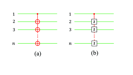
The focus of this work is on the implementation of the first type of multiqubit gate. A multiplex-controlled NOT gate (Fig.1a), with multiple qubits simultaneously controlling one target qubit, is often called as Toffoli gate [13]. For convenience, a multiplex-controlled phase gate (Fig.1b), with multiple qubits simultaneously controlling one target qubit, is denoted as a MCP gate throughout this paper. Over the past years, a number of theoretical proposals have been put forward for directly realizing a Toffoli gate or a MCP gate using matter qubits, such as trapped ionic qubits [14-16], quantum-dot qubits [17], atomic qubits [18-25], NV-center qubits [26,27], and superconducting qubits [28-31]. Experimentally, a three-qubit Toffoli gate or a three-qubit MCP gate of matter qubits was demonstrated in NMR quantum systems [32], superconducting qubits [33,34], or atomic systems [35]. Moreover, a four-qubit Toffoli gate was experimentally implemented with superconducting qubits [34]. On the other hand, theoretical proposals for realizing a Toffoli gate or MCP gate with photons have been presented by using linear optical setups [36-40] and linear optical devices plus auxiliary systems [41-43], and a three-qubit Toffoli gate of photons has been experimentally demonstrated in a linear-optical setup [44,45].
Quite different from [14-45], schemes have also been proposed to directly realize an -qubit Toffoli or MCP gate of photonic qubits by a cavity QED system [46] or a circuit QED system [47-49]. We note that the previous works [46-49] only apply to the case that the two logic states of each photonic qubit are encoded with a vacuum state and a single-photon state. In addition, we note that the Toffoli or MCP gates discussed in Refs. [46-49] were implemented essentially through step by step operations or by using a multi-level natural or artificial atom to couple multiple cavities. Generally speaking, decoherence from higher energy levels could be a severe issue when a multi-level quantum system is employed in the gate realization; and step-by-step operations are not desirable in experiments, which increases the experimental complexity and prolongs the operation time. For these reasons, in the following we will propose a simple and more general scheme for the direct implementation of a MCP gate with photonic qubits based on circuit QED. The circuit QED is analogue of cavity QED, it consists of superconducting (SC) qubits and microwave resonators or cavities, and has been considered as one of the most promising candidates for QIP [50-58]. In recent years, much attention has been paid to the QIP with microwave photons, because microwave photons can have lifetimes comparable to that of SC qubits [59].
As shown below, the present work works out for a more general case, i.e., the two logic states of each photonic qubit are encoded with a vacuum state and an arbitrary non-vacuum state (e.g., a single-photon state, a Fock state, a superposition of Fock states, a cat state, or a coherent state, etc.). The state here is orthogonal or quasi-orthogonal to the vacuum state. Moreover, the present work requires only a single-step operation and a two-level coupler (a SC qubit) to couple cavities, thus decoherence from higher energy levels is avoided in our gate realization and the gate implementation procedure is greatly simplified when compared to [46-49]. To the best of our knowledge, based on cavity QED or circuit QED, how to realize a MCP gate of photonic qubits by using a two-level coupler and through only a single-step operation has not been reported yet.
We stress that this work is on the implementation of a MCP gate with multiple control qubits simultaneously controlling one target qubit (Fig. 1b), thus it is obviously different from the previous works (e.g., [20,60-68]) on the realization of a multi-target-qubit gate with one control qubit simultaneously controlling multiple target qubits (Fig. 2).
This paper is organized as follows. In Sec. II, we give a brief introduction to the -qubit MCP gate and the -qubit Toffoli gate. In Sec. III, we explicitly show how to realize an -qubit MCP gate with photonic qubits each encoded via a vacuum state and a non-vacuum state. In Sec. IV, we discuss the orthogonality required by the qubit encoding. In Sec. V, we give a discussion on the circuit-QED based experimental feasibility of implementing a three-qubit MCP gate with each photonic qubit encoded via a vacuum state and a cat state, by using three one-dimensional (1D) microwave cavities coupled to a SC flux qubit. A concluding summary is given in Sec. VI.
II -qubit MCP gate and Toffoli gate
For qubits, there exist computational basis states, which form a set of complete orthogonal bases in a -dimensional Hilbert space of the qubits. An -qubit computational basis state is denoted as , where subscript represents qubit , and (). The -qubit MCP gate considered in this work (Fig. 1b) is described as follows:
(i) When the control qubits (say the first qubits) are all in the state , the state of the target qubit (the last qubit) is phase flipped as (i.e., one has the state transformation for the qubits), while the state of the target qubit remains unchanged.
(ii) When even one of the control qubits is not in the state nothing happens to both states and of the target qubit.
According to the description here, the -qubit MCP gate can be characterized by the following state transformation
| (1) |
which shows that after the MCP gate, the computational basis state of the qubits changes to while nothing happens to all other computational basis states of the qubits.
The -qubit Toffoli gate (Fig. 1a) is described by the following state transformation:
| (2) |
where the subscripts represent the qubits. Equation (2) implies that when the control qubits (the first qubits) are all in the state a bit flip (i.e., and ) happens to the states and of the target qubit (the last qubit). However, when even one of the control qubits is not in the state the states and of the target qubit remain unchanged.
Since a Toffoli gate can be constructed with a MCP gate (Fig. 1c), in the following we will mainly show how to implement the MCP gate (1) using photonic qubits based on circuit QED.
III Implementation of an -qubit MCP gate with photonic qubits
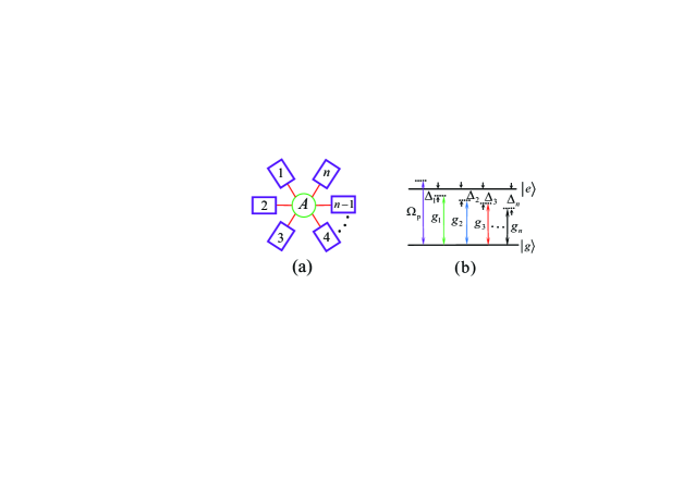
Let us consider a system consisting of cavities () coupled to a two-level coupler (Fig. 3a). The coupler here is a SC qubit with two levels and (Fig. 3b). Adjust the level spacings of the coupler such that cavity () is dispersively coupled to the transition of the coupler, with coupling constant and detuning (Fig. 3b). Note that for the coupler being a SC qubit, the level spacings can be rapidly (within ns) adjusted through changing the external control parameters (e.g., magnetic flux applied to the superconducting loop of a SC phase, transmon [69], Xmon [70], or flux qubit [71]). In addition, a classical pulse with frequency and initial phase is applied to the coupler. The pulse is dispersively coupled to the transition (Fig. 3b). In the interaction picture and after making a rotating-wave approximation, the Hamiltonian of the system is given by
| (3) |
where is the photon annihilation operator of cavity , is the Rabi frequency of the pulse, and (Fig. 3b). Here, is the transition frequency of the coupler, while is the frequency of cavity ().
For the dispersive coupling (large detuning), the energy exchange between cavity and the coupler can be neglected. Under the condition (where ), the interaction between the cavities, induced by the coupler, is negligible. In addition, assume so that the stark-shift effect of the coupler induced by the pulse is negligible. Under these considerations, based on the Hamiltonian (3), one can obtain the following effective Hamiltonian [72,73]
| (4) |
where and In a rotating frame under the Hamiltonian and by choosing it follows from the Hamiltonian (4)
| (5) |
For the gate purpose, we consider that each cavity is either in a vacuum state or an arbitrary non-vacuum state
| (6) |
where is an -photon Fock state. When the cavities are in the vacuum state the Hamiltonian (5) reduces to h.c., which rotates the coupler’s state as follows
| (7) |
On the other hand, when the cavities are not in the vacuum state, if the Rabi frequency of the driving pulse is much smaller than (i.e., ), the coupler’s state is not changed by the driving pulse due to the large detuning [74]. Here, is the average photon number of cavity (). In this sense, one has
| (8) |
where subscript represents cavity , is an abbreviation of the product state of cavities, and (i.e., the cavities are not in the vacuum state). Here, (), which is the state of cavity .
By applying a unitary operation to return to the original interaction picture, one has the following state transformation according to Eqs. (7) and (8)
| (9) |
| (10) |
In the following, we set (). If the coupler-cavity interaction time is chosen such that and ( is a positive integer while is a positive odd number), one has from Eqs. (9) and (10)
| (11) |
where we take for but for One can verify that the following equality holds
| (12) |
To see Eq. (12) clearly, let us consider a three-cavity case (i.e., ). Because of (), the product state of the three cavities is , , , , , or . By applying to these states, we have
| (13) | |||||
where we have used (see Eq. (6)) and applied Obviously, the state transformations given in Eq. (13) can be summarized as Eq. (12) for Following the same derivation as shown in Eq. (13), one can easily verify that Eq. (12) also holds for the case of
According to Eq. (12), we have from Eq. (11)
| (14) |
After dropping off the common phase factor it follows from Eq. (14)
| (15) |
where
Let us now consider photonic qubits (). Each photonic qubit is encoded as follows. Namely, the logic state of photonic qubit is represented by the vacuum state of cavity while the logic state of photonic qubit is represented by the non-vacuum state of cavity (). With this encoding, the state of the cavities corresponds to the computational basis state of the photonic qubits, and the state of the cavities corresponds to the computational basis state of the photonic qubits (). Note that we have because of (see the above). Thus, from the state transformation of the cavities in Eq. (15), one can obtain the following state transformation for the photonic qubits
| (16) |
where subscripts () represent the photonic qubits and , respectively. Note that the state transformation (16) is identical to that given in Eq. (1). Hence, an -qubit MCP gate described by Eq. (1) is implemented after the above operation. In addition, one can see from Eq. (15) that the coupler returns to its original ground state after the operation.
Before ending this section, some points may need to be addressed here:
(a) In above we have set (), which turns out into
| (17) |
This condition can be readily achieved by carefully selecting the detunings via prior adjustment of the cavity frequencies due to ( ).
(b) In above we have set
| (18) |
which results in
| (19) |
The condition (19) can be easily satisfied by adjusting the Rabi frequency of the pulse (e.g., through varying the pulse intensity).
(c) As mentioned above, the Hamiltonian (3) was constructed by adjusting the level spacings of the coupler. However, we should point out that adjusting the level spacings of the coupler is unnecessary. Alternatively, one can obtain the Hamiltonian (3) by tuning the frequency of each cavity. Note that the frequency of a superconducting microwave cavity or resonator can be rapidly tuned within a few nanoseconds [75,76].
(d) The single-step implementation of the -qubit MCP gate here can significantly simplify the realization of an -qubit Toffoli gate (Fig. 1a). This is because the -qubit Toffoli gate can be constructed by combining the -qubit MCP gate with two single-qubit Hadamard gates [13,28], which are performed on the target qubit before and after the -qubit MCP gate respectively (Fig.1c). However, using the conventional gate-constructing technique to construct a Toffoli gate, the required number of single- and two-qubit quantum gates increases drastically with an increasing number of qubits [9-12].
(e) As shown above, the -qubit MCP gate is realized through a single step of operation essentially described by the effective Hamiltonian (5), which is derived from the original Hamiltonian (3). In addition, neither measurement on the state of cavities nor measurement on the state of the coupler is needed.
IV Encoding and orthogonality
In the above, the two logic states of each photonic qubit are encoded with a vacuum state and an arbitrary non-vacuum state . We now give a brief discussion on the orthogonality required by the qubit encoding. In other words, to have the encoding effective, the orthogonality or quasi-orthogonality between the vacuum state and the non-vacuum state needs to hold, i.e.,
| (20) |
To name a few, we will provide some encodings for which the condition (20) applies:
(i) The two logic states of each photonic qubit are encoded with a vacuum state and a Fock state with photons (i.e., ). For this encoding, one has
(ii) The two logic states of each photonic qubit are encoded with a vacuum state and a superposition of Fock states (e.g., etc.). For this encoding, one has
(iii) The two logic states of each photonic qubit are encoded with a vacuum state and a Schrödinger cat state (e.g., where are coherent states and is a normalization factor). For this encoding, one has It is noted that the cat-state encoding, consisting of superpositions of coherent states, is protected against photon loss and dephasing errors [77,78], and quantum computing based on cat-state encoding has recently attracted much attention [68,79–81].
(iv) The two logic states of each photonic qubit are encoded with a vacuum state and a coherent state with a large enough One can check for a large enough
(v) The two logic states of each photonic qubit are encoded with a vacuum state and a multi-component Schrödinger cat state (e.g., where and are coherent states and is a normalization factor). For this encoding, one has
(vi) The two logic states of each photonic qubit are encoded with a vacuum state and a squeezed vacuum state with a large enough squeezed parameter Here, One can verify for a large enough
V Possible experimental feasibility
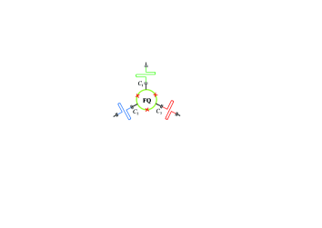
In the above, we have considered a two-level SC qubit as the coupler to couple multiple cavities. The SC qubit could be a SC phase, flux, transmon, or Xmon qubit, etc. As an example, we now give a discussion on the experimental feasibility of realizing a three-qubit MCP gate based on a circuit-QED system, which consists of three 1D microwave cavities (1,2,3) coupled to a SC flux qubit (Fig. 4). In this example, we consider that the two logic states and of each photonic qubit are encoded with a cat state and a vacuum state. In this case, we have
| (21) |
with The three photonic qubits (1,2,3) involved in the gate correspond to three microwave cavities (1,2,3), respectively.
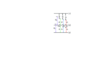
In reality, we need to consider the effect of the second excited level of the flux qubit and the inter-cavity crosstalk on the gate operation. Thus, we modify the Hamiltonian (3) as Here, is the Hamiltonian (3) given above (with ), and is given by
| (22) | |||||
where the terms in the first bracket represent the unwanted coupling of the three cavities with the transition with coupling constant and detuning () (Fig. 5), the terms in the second bracket represent the unwanted coupling between the pulse and the transition with Rabi frequency (Fig. 5), while the terms in the last bracket represent the inter-cavity crosstalk with the crosstalk strength and frequency detuning between the two cavities and Here, Note that the coupling of the cavities and the pulse with the transition is negligible because of (Fig. 5). Here, () is the () transition frequency of the qubit.
After considering the system dissipation and dephasing, the dynamics of the lossy system is determined by the master equation
| (23) | |||||
where is the density matrix of the whole system; is the modified Hamiltonian given above; (with ), , and () is the dephasing rate of the level (); is the energy relaxation rate of the level ; () is the () energy relaxation rate of the level of the qubit; while is the decay rate of cavity ().
The fidelity of the whole operation is given by where is the ideal output state obtained under the theoretical model, while is the final density matrix of the whole system (i.e., the three cavities and the flux qubit) obtained by numerically solving the master equation. As an example, let us consider an input state of the whole system where (), with given in Eq. (21). Thus, according to Eq. (15), the ideal output state of the whole system is after applying a three-qubit MCP gate.
| | ||
| | ||
| | ||
| | ||
| | ||
| | ||
| | ||
For a superconducting flux qubit, the transition frequency between adjacent energy levels can be 1 to 20 GHz [82-84]. As an example, consider the parameters listed in Table 1, which are used in our numerical simulations. The coupling constants and are calculated according to Eq. (17). In addition, is calculated for and according to Eq. (19). The pulse frequency is calculated based on The dipole matrix elements between any two of the three levels , , and can be made to be on the same order of magnitude via properly designing the flux qubit [85]. Thus, we choose and () for simplicity. In addition, we consider , with (). Other parameters used in the numerical simulations are: (i) , , , (ii) , (iii) ( ), (iv) .
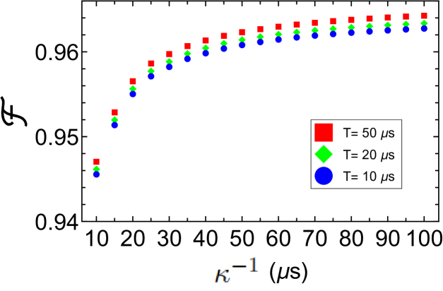
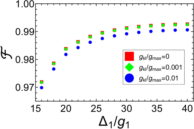
By solving the master equation (23), we numerically plot Fig. 6 to illustrate the fidelity versus for s. Figure 6 shows that when the decay rate of the cavities increases, the gate fidelity quickly drops. This is because the present work focuses on the gate with photonic qubits and thus photons are always populated in each cavity during the gate realization. Nevertheless, one can see from Fig. 6 that for s and s, the fidelity exceeds . The imperfect fidelity is also caused by the unwanted couplings of the cavities (and the pulse) with the irrelevant levels of the flux qubit as well as the decoherence of the flux qubit. In addition, the imperfect fidelity is caused due to that the large detuning conditions are not well satisfied. We remark that the fidelity can be further improved by reducing the errors via optimizing the systematic parameters. As demonstrated in Fig. 7, a high fidelity greater than can be achieved for and when the unwanted couplings of the cavities (and the pulse) with the transition of the flux qubit and the dissipation of the system are negligible.
The maximum among the coupling constants is GHz, which is available in experiments because a coupling strength GHz was reported for a superconducting flux qubit coupled to a 1D microwave cavity [86]. As an example, consider s. In this case, the decoherence times of the flux qubit used in the numerical simulations are s s. Note that decoherence time 70 s to 1 ms for a superconducting flux qubit has been demonstrated in experiments [87,88]. Hence, the decoherence time of the flux qubit considered in the numerical simulation is a rather conservative case. In addition, the crosstalk strength used in the numerical simulation can be obtained by prior design of the coupling capacitances between the cavities and the coupler qubit [89].
With the detunings and the coupling constants listed in Table 1 (), one finds the effective coupling constant MHz, which results in MHz for and used in the numerical simulation. According to Eq. (18), the operation time is given by For and MHz, a simple calculation gives the operation time s, much shorter than the qubit decoherence time applied in the numerical simulation and the cavity decay time s s considered in Fig. 6. For s and the cavity frequencies given above, the quality factors for the three cavities (1,2,3) are respectively and which can be achieved because a 1D microwave cavity or resonator with a high quality factor was experimentally demonstrated [90,91]. The analysis given above implies that implementation of a three-qubit MCP gate using photonic qubits is feasible with the present circuit QED technology.
VI Conclusion
We have proposed an efficient scheme to implement an -qubit MCP gate, i.e., a multiplex-controlled phase gate with photonic qubits simultaneously controlling one photonic target qubit, based on circuit QED. As shown above, this scheme is universal, because the two logic states of each photonic qubit can be encoded via a vacuum state and an arbitrary non-vacuum state (e.g., a Fock state, a superposition of Fock states, a cat state, or a coherent state, etc.), which is orthogonal or quasi-orthogonal to the vacuum state. In addition, this scheme is simple because it requires only one step of operation.
This scheme has additional distinguishing features: (i) Since only two levels of the coupler are used, i.e., no auxiliary levels are utilized, decoherence from the higher energy levels of the coupler is avoided; (ii) The gate operation time is independent of the number of qubits, thus it does not increase with the increasing number of qubits; and (iii) The gate implementation is deterministic because no measurement is needed.
As an example, we have numerically analyzed the circuit-QED based experimental feasibility of realizing a three-qubit MCP gate with each photonic qubit encoded via a vacuum state and a cat state. This scheme can be applied to implement the MCP gate using photonic qubits in a wide range of physical system, which consists of multiple microwave or optical cavities coupled to a two-level coupler such as a natural atom or an artificial atom (e.g., a quantum dot, an NV center, or a supercoducting qubit, etc.). Finally, it is noted that an -qubit Toffoli gate of photonic qubits can be realized, by applying the present scheme to implement an -qubit MCP gate of photonic qubits, plus a single-qubit Hadamard transformation on the target qubit before and after the -qubit MCP gate.
Acknowledgements
This work was partly supported by the National Natural Science Foundation of China (NSFC) (11074062, 11374083, 11774076, U21A20436), the Key-Area Research and Development Program of GuangDong province (2018B030326001), the Jiangxi Natural Science Foundation (20192ACBL20051).
References
- (1) P. W. Shor, in Proceedings of the 35th Annual Symposium on Foundations of Computer Science, edited by S. Goldwasser (IEEE Computer Society, Los Alamitos, CA, 1994), pp. 124
- (2) L. K. Grover, Quantum Computers can Search Rapidly by using Almost any Transformation, Phys. Rev. Lett. 80, 4329 (1998)
- (3) T. Beth and M. Röteler, in Quantum Information (Springer, Berlin, 2001), Vol. 173, Chap. 4, p. 96
- (4) P. W. Shor, Scheme for reducing decoherence in quantum computer memory, Phys. Rev. A 52, R2493 (1995)
- (5) A. M. Steane, Error Correcting Codes in Quantum Theory, Phys. Rev. Lett. 77, 793 (1996)
- (6) F. Gaitan, in Quantum Error Correction and Fault Tolerant Quantum Computing (CRC Press, Boca Raton, FL, 2008), pp. 1-312
- (7) S. L. Braunstein, V. Bužek, and M. Hillery, Quantum information distributors: Quantum network for symmetric and asymmetric cloning in arbitrary dimension and continuous limit, Phys. Rev. A 63, 052313 (2001)
- (8) M. Šašura and V. Bužek, Multiparticle entanglement with quantum logic networks: Application to cold trapped ions, Phys. Rev. A 64, 012305 (2001)
- (9) A. Barenco, C. H. Bennett, R. Cleve, D. P. DiVincenzo, N. Margolus, P. Shor, T. Sleator, J. A. Smolin, and H. Weinfurter, Elementary gates for quantum computation, Phys. Rev. A 52, 3457 (1995)
- (10) N. Khaneja and S. J. Glaser, Cartan decomposition of SU(2n) and control of spin systems, Chem. Phys. 267, 11 (2001)
- (11) M. Mötöen, J. J. Vartiainen, V. Bergholm, and M. M. Salomaa, Quantum circuits for general multiqubit gates, Phys. Rev. Lett. 93, 130502 (2004)
- (12) Y. Liu, G. L. Long, and Y. Sun, Analytic one-bit and CNOT gate constructions of general n-qubit controlled gates, Int. J. Quantum Inform. 6, 447 (2008)
- (13) M. A. Nielsen and I. L. Chuang, Quantum Computation and Quantum Information (Cambridge University Press, Cam bridge, England, 2001)
- (14) X. Wang, A. Sørensen, and K. Mølmeret, Multibit Gates for Quantum Computing, Phys. Rev. Lett. 86, 3907 (2001)
- (15) T. Monz, K. Kim, W. Hänsel, M. Riebe, A. S. Villar, P. Schindler, M. Chwalla, M. Hennrich, and R. Blatt, Realization of the Quantum Toffoli Gate with Trapped Ions, Phys. Rev. Lett. 102, 040501 (2009)
- (16) P. Z. Zhao, G. F. Xu, and D. M. Tong, Nonadiabatic holonomic multiqubit controlled gates, Phys. Rev. A 99, 052309 (2019)
- (17) H. R. Wei and F. G. Deng, Universal quantum gates for hybrid systems assisted by quantum dots inside double-sided optical microcavities, Phys. Rev. A 87, 022305 (2013)
- (18) L. M. Duan, B. Wang, and H. J. Kimble, Robust quantum gates on neutral atoms with cavity-assisted photon-scattering, Phys. Rev. A 72, 032333 (2005)
- (19) X. Zou, Y. Dong, and G. C. Guo, Implementing a conditional z gate by a combination of resonant interaction and quantum interference, Phys. Rev. A 74, 032325 (2006)
- (20) M. Waseem, M. Irfan, and S. Qamar, Realization of quantum gates with multiple control qubits or multiple target qubits in a cavity, Quantum Inf. Process 14, 1869 (2015)
- (21) Y. Liang, Q. C. Wu, S. L. Su, X. Ji, and S. Zhang, Shortcuts to adiabatic passage for multiqubit controlled-phase gate, Phys. Rev. A 91, 032304 (2015)
- (22) S. L. Su, H. Z. Shen, E. Liang, and S. Zhang, One-step construction of the multiple-qubit Rydberg controlled-PHASE gate, Phys. Rev. A 98, 032306 (2018)
- (23) Y. Hao, G. Lin, Y. Niu, and S. Gong, One-step implementation of a multiqubit controlled-phase-flip gate in coupled cavities, Quant. Inf. Proc. 18, 18 (2019)
- (24) T. H. Xing, X. Wu, and G. F. Xu, Nonadiabatic holonomic three-qubit controlled gates realized by one-shot implementation, Phys. Rev. A 101, 012306 (2020)
- (25) M. Khazali and K. Mølmer, Fast Multiqubit Gates by Adiabatic Evolution in Interacting Excited-State Manifolds of Rydberg Atoms and Superconducting Circuits, Phys. Rev. X 10, 021054 (2020)
- (26) W. L. Yang, Z. Q. Yin, Z. Y. Xu, M. Feng, and J. F. Du, One step implementation of multi-qubit conditional phase gating with nitrogen-vacancy centers coupled to a high-Q silica microsphere cavity, Appl. Phys. Lett. 96, 241113 (2010)
- (27) T. Wang and Y. Zhang, Scalable multi-qubit quantum gates in quantum networks based on the microtoroidal-resonator mediated nitrogen-vacancy centers in diamond, J. Opt. Soc. Am. B 37, 1372 (2020)
- (28) C. P. Yang and S. Han, n-qubit-controlled phase gate with superconducting quantum-interference devices coupled to a resonator, Phys. Rev. A 72, 032311 (2005)
- (29) C. P. Yang and S. Han, Realization of an n-qubit controlled- gate with superconducting quantum interference devices or atoms in cavity QED, Phys. Rev. A 73, 032317 (2006)
- (30) W. A. Li and Y. Chen, Simplified proposal for realizing a multiqubit tunable phase gate in circuit QED, J. Opt. Soc. Am. B 34 , 1560 (2017)
- (31) B. Ye, Z. F. Zheng, and C. P. Yang, Multiplex-controlled phase gate with qubits distributed in a multicavity system, Phys. Rev. A 97, 062336 (2018)
- (32) J. Zhang, W. Liu, Z. Deng, Z. Lu, and G. L. Long, Modularization of multi-qubit controlled phase gate and its NMR implementation, J. Opt. B: Quantum Semiclass. Opt. 7, 22 (2005)
- (33) A. Fedorov, L. Steffen, M. Baur, M. P. D. Silva, and A. Wallraff, Implementation of a Toffoli gate with superconducting circuits, Nature 481, 170 (2012)
- (34) C. Song, S. B. Zheng, P. Zhang, K. Xu, L. Zhang, Q. Guo, W. Liu, D. Xu, H. Deng, K. Huang, D. Zheng, X. Zhu, and H. Wang, Continuous-variable geometric phase and its manipulation for quantum computation in a superconducting circuit, Nat. Commun. 8, 1061 (2017)
- (35) H. Levine, A. Keesling, G. Semeghini, A. Omran, T. T. Wang, S. Ebadi, H. Bernien, M. Greiner, V. Vuletić, H. Pichler, and M. D. Lukin, Parallel Implementation of High-Fidelity Multiqubit Gates with Neutral Atoms, Phys. Rev. Lett. 123, 170503 (2019)
- (36) J. Fiurášek, Linear-optics quantum Toffoli and Fredkin gates, Phys. Rev. A 73, 062313 (2006)
- (37) T. C. Ralph, K. J. Resch, and A. Gilchrist, Efficient Toffoli gates using qudits, Phys. Rev. A 75, 022313 (2007)
- (38) H. L. Huang, W. S. Bao, T. Li, F. G. Li, X. Q. Fu, S. Zhang, H. L. Zhang, and X. Wang, Deterministic linear optical quantum Toffoli gate, Phys. Lett. A 381, 2673 (2017)
- (39) L. Dong, S. L. Wang, C. Cui, X. Geng, Q. Y. Li, H. K. Dong, X. M. Xiu, and Y. J. Gao, Polarization Toffoli gate assisted by multiple degrees of freedom, Opt. Lett. 43, 4635 (2018)
- (40) X. Zou, K. Li, and G. Guo, Linear optical scheme for direct implementation of a nondestructive N-qubit controlled phase gate, Phys. Rev. A 74, 044305 (2006)
- (41) H. R. Wei and G. L. Long, Universal photonic quantum gates assisted by ancilla diamond nitrogen-vacancy centers coupled to resonators, Phys. Rev. A 91, 032324 (2015)
- (42) H. R. Wei, F. G. Deng, and G. L. Long, Hyper-parallel Toffoli gate on three-photon system with two degrees of freedom assisted by single-sided optical microcavities, Opt. Express 24, 18619 (2016)
- (43) B. Y. Xia, C. Cao, Y. H. Han, and R. Zhang, Universal photonic three-qubit quantum gates with two degrees of freedom assisted by charged quantum dots inside single-sided optical microcavities, Laser Phys. 28, 095201 (2018)
- (44) M. Mičuda, M. Sedlák, I. Straka, M. Miková M. Dus ĕk, M. Ježek, and J. Fiurášek, Efficient Experimental Estimation of Fidelity of Linear Optical Quantum Toffoli Gate, Phys. Rev. Lett. 111, 160407 (2013)
- (45) S. Ru, Y. Wang, M. An, F. Wang, P. Zhang, and F. Li, Realization of deterministic quantum Toffoli gate with a single photon, Phys. Rev. A 103, 022606 (2021)
- (46) P. M. Lu, J. Song, and Y. Xia, Implementing a Multi-Qubit Quantum Phase Gate Encoded by Photonic Qubit, Chin. Phys. Lett. 27 (3), 030302 (2010)
- (47) M. Hua, M. J. Tao, and F. G. Deng, Universal quantum gates on microwave photons assisted by circuit quantum electrodynamics, Phys. Rev. A 90, 012328 (2014)
- (48) M. Hua, M. J. Tao, and F. G. Deng, Fast universal quantum gates on microwave photons with all-resonance operations in circuit QED, Sci. Rep. 5, 9274 (2015)
- (49) J. X. Han, J. L. Wu, Y. Wang, Y. Y. Jiang, Y. Xian, and J. Song, Multi-qubit phase gate on multiple resonators mediated by a superconducting bus, Opt. Express 28, 1954 (2020)
- (50) C. P. Yang, S. I. Chu, and S. Han, Possible realization of entan glement, logical gates and quantum information transfer with superconducting-quantum-interference-device qubits in cavity QED, Phys. Rev. A 67, 042311 (2003)
- (51) J. Q. You and F. Nori, Quantum information processing with superconducting qubits in a microwave field, Phys. Rev. B 68, 064509 (2003)
- (52) A. Blais, R. S. Huang, A. Wallraff, S. M. Girvin, and R. J. Schoelkopf, Cavity quantum electrodynamics for superconduct ing electrical circuits: An architecture for quantum computation, Phys. Rev. A 69 , 062320 (2004)
- (53) J. Q. You and F. Nori, Superconducting circuits and quantum information, Phys. Today 58(11), 42 (2005)
- (54) J. Q. You and F. Nori, Atomic physics and quantum optics using superconducting circuits, Nature (London) 474, 589-597 (2011)
- (55) I. Buluta, S. Ashhab, and F. Nori, Natural and artificial atoms for quantum computation, Rep. Prog. Phys. 74, 104401 (2011)
- (56) Z. L. Xiang, S. Ashhab, J. Q. You, and F. Nori, Hybrid quantum circuits: Superconducting circuits interacting with other quan tum systems, Rev. Mod. Phys. 85, 623 (2013)
- (57) X. Gu, A. F. Kockum, A. Miranowicz, Y. X. Liu, and F. Nori, Microwave photonics with superconducting quantum circuits, Phys. Rep. 718, 1 (2017)
- (58) Q. P. Su, H. Zhang, and C. P. Yang, Transferring quantum entangled states between multiple single-photon-state qubits and coherent-state qubits in circuit QED, Front. Phys. 16(6), 61501 (2021)
- (59) M. H. Devoret and R. J. Schoelkopf, Superconducting circuits for quantum information: an outlook, Science 339, 1169 (2013)
- (60) C. H. Bai, D. Y. Wang, S. Hu, W. X. Cui, X. X. Jiang, and H. F. Wang, Scheme for implementing multitarget qubit controlled-NOT gate of photons and controlled-phase gate of electron spins via quantum dot-microcavity coupled system, Quantum. Inf. Process 15, 1485 (2016)
- (61) B. Ye, Z. F. Zheng, Y. Zhang, and C. P. Yang, Circuit QED: single-step realization of a multiqubit controlled phase gate with one microwave photonic qubit simultaneously controlling microwave photonic qubits, Opt. Express 26, 30689 (2018)
- (62) C. P. Yang, Y. X. Liu, and F. Nori, Phase gate of one qubit simultaneously controlling n qubits in a cavity, Phys. Rev. A 81, 062323 (2010)
- (63) C. P. Yang, S. B. Zheng, and F. Nori, Multiqubit tunable phase gate of one qubit simultaneously controlling n qubits in a cavity, Phys. Rev. A 82, 062326 (2010)
- (64) M. Waseem, M. Irfan, and S. Qamar, Multiqubit quantum phase gate using four-level superconducting quantum interference devices coupled to superconducting resonator, Physica C 477, 24 (2012)
- (65) C. P. Yang, Q. P. Su, F. Y. Zhang, and S. B. Zheng, Single-step implementation of a multiple-target-qubit controlled phase gate without need of classical pulses, Opt. Lett. 39, 3312 (2014)
- (66) H. F. Wang, A. D. Zhu, and S. Zhang, One-step implementation of a multiqubit phase gate with one control qubit and multiple target qubits in coupled cavities, Opt. Lett. 39, 1489 (2014)
- (67) T. Liu, X. Z. Cao, Q. P. Su, S. J. Xiong, and C. P. Yang, Multi-target-qubit unconventional geometric phase gate in a multicavity system, Sci. Rep. 6, 21562 (2016)
- (68) Y. J. Fan, Z. F. Zheng, Y. Zhang, D. M. Lu, and C. P. Yang, One-step implementation of a multi-target-qubit controlled phase gate with cat-state qubits in circuit QED, Front. Phys. 14(2), 21602 (2019)
- (69) P. J. Leek, S. Filipp, P. Maurer, M. Baur, R. Bianchetti, J. M. Fink, M. Göppl, L. Steffen, and A. Wallraff, Using sideband transitions for two-qubit operations in superconducting circuits, Phys. Rev. B 79, 180511 (2009)
- (70) R. Barends, J. Kelly, A. Megrant, D. Sank, E. Jeffrey, Y. Chen, Y. Yin, B. Chiaro, J. Mutus, C. Neill, P. O’Malley, P. Roushan, J. Wenner, T. C. White, A. N. Cleland, and J. M. Martinis, Coherent Josephson qubit suitable for scalable quantum integrated circuits, Phys. Rev. Lett. 111, 080502 (2013)
- (71) M. Neeley, M. Ansmann, R. C. Bialczak, M. Hofheinz, N. Katz, Erik Lucero, A. O’Connell, H. Wang, A. N. Cleland, and J. M. Martinis, Process tomography of quantum memory in a Josephson-phase qubit coupled to a two-level state, Nat. Phys. 4, 523 (2008)
- (72) A. Sørensen, and K. Mølmeret, Quantum Computation with Ions in Thermal Motion, Phys. Rev. Lett. 82, 1971 (1999)
- (73) D. F. V. James and J. Jerke, Effective Hamiltonian theory and its applications in quantum information, Can. J. Phys. 85, 625 (2007)
- (74) Y. Xu, Y. Ma, W. Cai, X. Mu, W. Dai, W. Wang, L. Hu, X. Li, J. Han, H. Wang et al., Demonstration of Controlled-Phase Gates between Two Error-Correctable Photonic Qubits, Phys. Rev. Lett. 124(12), 120501 (2020)
- (75) M. Sandberg, C. M. Wilson, F. Persson, T. Bauch, G. Johansson, V. Shumeiko, T. Duty, and P. Delsing, Tuning the field in a microwave resonator faster than the photon lifetime, Appl. Phys. Lett. 92, 203501 (2008)
- (76) Z. L. Wang, Y. P. Zhong, L. J. He, H. Wang, J. M. Martinis, A. N. Cleland, and Q. W. Xie, Quantum state characterization of a fast tunable superconducting resonator, Appl. Phys. Lett. 102, 163503 (2013)
- (77) Z. Leghtas, G. Kirchmair, B. Vlastakis, R. J. Schoelkopf, M. H. Devoret, and M. Mirrahim, Hardware-Efficient Autonomous Quantum Memory Protection, Phys. Rev. Lett. 111, 120501 (2013)
- (78) M. Mirrahimi, Z. Leghtas, V. V. Albert, S. Touzard, R. J. Schoelkopf, L. Jiang, and M. H. De voret, Dynamically protected cat-qubits: a new paradigm for universal quantum computation, New J. Phys. 16, 045014 (2014)
- (79) J. Guillaud and M. Mirrahimi, Repetition cat qubits for fault-tolerant quantum computation, Phys. Rev. X 9, 041053 (2019)
- (80) C. Chamberland, K. Noh, P. Arrangoiz-Arriola, E. T. Campbell, C. T. Hann, J. Iverson, H. Putterman, T. C. Bohdanowicz, S. T. Flammia, A. Keller et al., Building a fault-tolerant quantum computer using concatenated cat codes, arXiv:2012.04108
- (81) T. Liu, Z. F. Zheng, Y. Zhang, Y. L. Fang, and C. P. Yang, Transferring entangled states of photonic cat-state qubits in circuit QED, Front. Phys. 15(2), 21603 (2020)
- (82) A. O. Niskanen, K. Harrabi, F. Yoshihara, Y. Nakamura, S. Lloyd, and J. S. Tsai, Quantum Coherent Tunable Coupling of Superconducting Qubits, Science 316, 723 (2007)
- (83) K. Inomata, T. Yamamoto, P. M. Billangeon, Y. Nakamura, and J. S. Tsai, Large dispersive shift of cavity resonance induced by a superconducting flux qubit in the straddling regime, Phys. Rev. B 86(14), 140508 (2012)
- (84) Z. H. Peng, Y. X. Liu, J. T. Peltonen, T. Yamamoto, J. S. Tsai, and O. Astafiev, Correlated Emission Lasing in Harmonic Oscillators Coupled via a Single Three-Level Artificial Atom, Phys. Rev. Lett. 115(22), 223603 (2015)
- (85) Y. X. Liu, J. Q. You, L. F. Wei, C. P. Sun, and F. Nori, Optical selection rules and phase dependent adiabatic state control in a superconducting quantum circuit, Phys. Rev. Lett. 95(8), 087001 (2005)
- (86) T. Niemczyk, F. Deppe, H. Huebl, E. P. Menzel, F. Hocke, M. J. Schwarz, J. J. Garcia-Ripoll, D. Zueco, T. Hümmer, E. Solano, A. Marx, and R. Gross, Circuit quantum electrodynamics in the ultrastrong coupling regime, Nat. Phys. 6(10), 772 (2010)
- (87) F. Yan, S. Gustavsson, A. Kamal, J. Birenbaum, A. P. Sears, D. Hover, T. J. Gudmundsen, J. L. Yoder, T. P. Orlando, J. Clarke, A. J. Kerman, and W. D. Oliver, The Flux Qubit Revisited to Enhance Coherence and Reproducibility, Nat. Commun. 7, 12964 (2016)
- (88) J. Q. You, X. Hu, S. Ashhab, and F. Nori, Low-decoherence flux qubit, Phys. Rev. B 75(14), 140515 (2007)
- (89) C. P. Yang, Q. P. Su, and S. Han, Generation of Greenberger-Horne-Zeilinger entangled states of photons in multiple cavities via a superconducting qutrit or an atom through resonant interaction, Phys. Rev. A 86, 022329 (2012)
- (90) G. Calusine, A. Melville, W. Woods, R. Das, C. Stull, V. Bolkhovsky, D. Braje, D. Hover, D. K. Kim, X. Miloshi et al., Analysis and mitigation of interface losses in trenched superconducting coplanar waveguide resonators, Appl. Phys. Lett. 112, 062601 (2018)
- (91) W. Woods, G. Calusine, A. Melville, A. Sevi, E. Golden, D. K. Kim, D. Rosenberg, J. L. Yoder, and W. D. Oliver, Determining interface dielectric losses in superconducting coplanar-waveguide resonators, Phys. Rev. Appl. 12, 014012 (2019)